IMST 404600 User manual

IMST GmbH
Carl-Friedrich-Gauß-Str. 2-4, D-47475 Kamp-Lintfort
Wireless M-Bus Range Extender
User Manual
Version 1.0
Document State
final
Date
June 2020
Document ID
4000/40140/0153
© 2020 IMST GmbH - All rights reserved
Wireless M-Bus Range Extender / / User Manual Version 1.0 Page 2 of 32
History
Version Date Comment
1.0 June 2020 Initial Version
Content
General User Information / Disposal
Safety
Overview
Range Extender Hardware
Initial Setup
Installation
Functional Description
Range Extender Startup
Calendar Events
Wireless M-Bus Packet Filter
Recording of Wireless M-Bus Packets
Upload of captured Wireless M-Bus Packets
Transport Protocol Details
Range Extender Status Information
LED Usage
LoRaWAN® Ports
Firmware Update via Bootloader
Technical Characteristics
Packet Decoding and Reassembly on Application Server Side
FAQ
Wireless M-Bus Range Extender / / User Manual Version 1.0 Page 3 of 32
General User Information / Disposal
This document has to be treated confidentially. The content must not be published, duplicated or passed to third parties without our express
permission.
Read this documentation attentively before initial operation or use of the Wireless M-Bus Range Extender.
Observe the safety instructions and warnings in this documentation.
Keep the user manual for future reference.
Product Information
Device: Wireless M-Bus Range Extender
Proper use: The Wireless M-Bus Range Extender is a compact and cost-effective device that collects wireless M-Bus messages from utility
meters and forwards them to a LoRaWAN® network.
Order Number: 404600
Manufacturer:
IMST GmbH
Carl-Friedrich-Gauss-Str. 2-4, 47475 Kamp-Lintfort, Germany
Disposal of the Device
Do not dispose this product at the end of its life in the household
waste, but in the designated places for recycling old electrical
equipment.
Do not dispose the battery cell in the household waste, but in the
designated areas for recycling old batteries.
Disclaimer
IMST GmbH points out that all information in this document are given on an “as is” basis. No guarantee, neither explicit nor implicit is given
for the correctness at the time of publication.
IMST GmbH reserves all rights to make corrections, modifications, enhancements, and other changes to its products and services at any
time and to discontinue any product or service without prior notice. It is recommended for customers to refer to the latest relevant information
before placing orders and to verify that such information is current and complete. All products are sold and delivered subject to “General
Terms and Conditions” of IMST GmbH, supplied at the time of order acknowledgment.
IMST GmbH assumes no liability for the use of its products and does not grant any licenses for its patent rights or for any other of its
intellectual property rights or third-party rights. It is the customer’s duty to bear responsibility for compliance of systems or units in which
products from IMST GmbH are integrated with applicable legal regulations. Customers should provide adequate design and operating
safeguards to minimize the risks associated with customer products and applications.
The product is not approved for use in life supporting systems or other systems whose malfunction could result in personal injury to the user.
Customers using the product within such applications do so at their own risk.
Any resale of IMST GmbH products or services with statements different from or beyond the parameters stated by IMST GmbH for that
product/solution or service is not allowed and voids all express and any implied warranties. The limitations on liability in favor of IMST GmbH
shall also affect its employees, executive personnel and bodies in the same way. IMST GmbH is not responsible or liable for any such wrong
statements.

Wireless M-Bus Range Extender / / User Manual Version 1.0 Page 4 of 32
Safety
General
Read this safety information attentively before using and operation of the Wireless M-Bus Range Extender
Do not make any changes to the product. The housing may only be opened for the initial configuration of the Wireless M-Bus Range
Extender and only by qualified specialist personnel. The housing must then be closed again for further operation.
Please do not use the device, if it appears to be damaged.
Battery Instructions
The Wireless M-Bus Range Extender is equipped with a non-rechargeable, 3.6V lithium battery cell with a typical capacitance of 19Ah. The
battery .must be treated as dangerous good
.Please note the following information
Only use the admitted battery cell (see )Technical Characteristics
Battery cells with a nominal voltage of more than 3.6V are not allowed.
Do not recharge the battery cell.
Do not disassemble the battery cell.
Do not heat the battery cell above 100 °C.
Keep batteries away from the reach of children.
Transport Notes
The Wireless M-Bus Range Extender is equipped with a non-rechargeable 3.6V lithium battery cell with a typical capacitance of 19Ah. The
battery must be treated as , UN3091 Class 9.dangerous good
Please note the following information regarding transport of the Wireless M-Bus Range Extender.
Certain transport and packaging regulations must be observed.
Use special packaging (Best case the same package where you received the Wireless M-Bus Range Extender with).
Mark the package with a appropriate sticker regarding the mode of transportation (street, train, ...).
Disconnect the battery cell connector from the power supply connector of the PCB.
Place a protection tape at the battery cell connector to avoid short circuit.
If you are uncertain about the transport please contact the vendor.
Transport within Airplanes is not allowed
Wireless M-Bus Range Extender / / User Manual Version 1.0 Page 5 of 32
Overview
The Wireless M-Bus standard (EN 13757-4) is used in many wireless and smart applications aresensor meter . These meters and sensors
communicating according to defined radio operation modes based on a standard FSK modulation with more or less range to the
corresponding receiving unit.
The LoRa® modulation has become the standard wireless technology for outdoor and indoor applications which require a perfect trade-off
among communication range and battery life. Therefore it is a perfect means to increase the range of wireless communication systems. The
Wireless M-Bus Range Extender in the following referred to as Range Extender combines the two modulation technics and communication
protocol stacks in one single device.
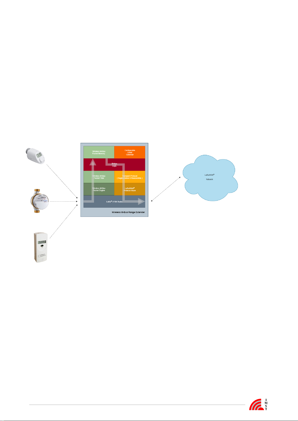
A typical usecase for the Range Extender is the forwarding of Wireless M-Bus messages of a configurable group of sensor / meter devices T.
he Range Extender offers a flexible way to define hourly, daily, weekly or monthly reception windows for sampling of WM-Bus messages and
a large data memory for temporary buffering. Even large WM-Bus messages with maximum payload size can be forwarded within LoRaWAN
radio packets by means of an integrated segmentation & reassembly protocol.
®
Configuration of firmware parameters like LoRaWAN settings, calendar events, packet filters can be easily managed via serial USB link and
®
PC-Tool. Calendar events and packet filters can furthermore be updated over the air.
Figure: Overview

Wireless M-Bus Range Extender / / User Manual Version 1.0 Page 6 of 32
Range Extender Hardware
Figure: Wireless M-Bus Range Extender without cover
Hardware Features
Power Supply via Battery.
Radio module including TRX, µC and additional PCB antenna.
Data memory
User Interface for configuration and signalling
The following explains some hardware features, necessary for the user to power and configure the Range Extender.
Power Supply
Power for the Rage Extender is supplied via the 2-pin connector JST B2B-PH-K-S.
Figure: Power Connector
Default power source is one non-rechargeable 3.6V LTC (Lithium-Thionylchlorid, Li-SOCl2) battery cell. It is equipped with a cable and the
2-pin connector JST PHR-2.
Battery Notes
Battery cells with a nominal voltage of more than 3.6V are not allowed.
Do not recharge the battery cell.
Do not disassemble, or heat the battery cell above 100 °C.
Dispose the battery cell only in designated areas for recycling old batteries.

Wireless M-Bus Range Extender / / User Manual Version 1.0 Page 7 of 32
User Interface
Reed Sensor: to be used as magnetic switch with a simple magnet for external user actions, without a need to open the housing.
LED for signalling.
nInternal Reset Butto for manual Reset after configuration of LoRaWAN settings.
®
Interface:Internal Configuration
Serial Configuration Interface (UART):
configuration of calendar events for WM-Bus reception intervals.
configuration of device filtering by Manufacturer ID, Device ID, ... (whitelist).
firmware upload via integrated bootloader (see ).Firmware Update via Bootloader
pin compatible to FTDI's (TTL to USB serial converter cable).TTL-232R-3V3
2 Pin-Header for activating the internal bootloader.
Figure: Configuration Interface
Serial Configuration Interface
Pin Name Type Description
1 GND GND
2 NC - currently not connected
3 NC - currently not connected
4 RxD Input UART receive data input of the radio module
5 TxD Output UART transmit data output of the radio module
6 NC - currently not connected
Wireless M-Bus Range Extender / / User Manual Version 1.0 Page 8 of 32
1.
2.
3.
4.
5.
Initial Setup
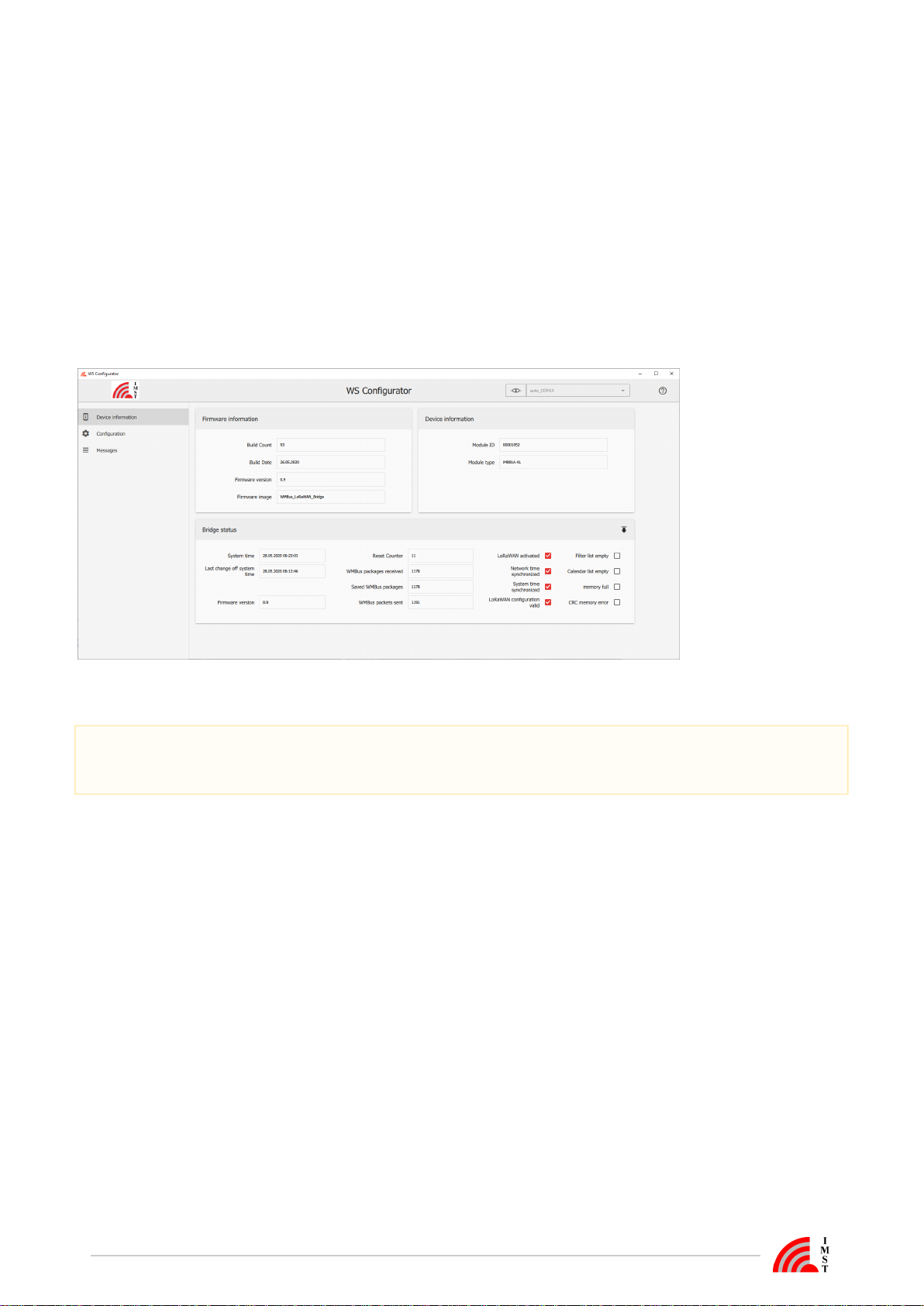
The Wirelesss M-Bus Range Extender requires an initial configuration before usage. This configuration can be done by means of a PC-Tool
called which is connected via serial interface to the device.WS Configurator
The configuration includes the following steps:
Setup of LoRaWAN including activation type for Over The Air Activation ( ) or Activation byprotocol parameter
®OTAA
Personalization ( ) and the corrosponding keys and identifiersABP
Reset of connected Range Extender
Synchronize the embedded RTC with the local PC time
Setup of calendar events which control the runtime behaviour of this device
Configuration of Wireless M-Bus address parameters for packet filtering
Figure : WS Configurator
It is recommended to perform a reset whenever the LoRaWAN settings have been updated!
®
Do not forget to synchronize the embedded RTC of the Range Extender with the PC time afterwards!

Wireless M-Bus Range Extender / / User Manual Version 1.0 Page 9 of 32
Installation
The Wireless M-Bus Range Extender housing consists of mounting brackets for fastening on a flat surface. Installation height must not be
higher than 2 meters above ground to avoid any risks in case of falling down.
The figure below shows the positions of the LED, the Reed Sensor and especially the integrated PCB antenna.
For optimal RF performance please avoid any metal obstacles near the antenna area.
If possible, avoid to install the module directly next to other radio equipment.
After powering up the Wireless M-Bus Range Extender by connecting the battery cell to the power connector the Range Extender performs
its startup procedure and starts working depending on the current configuration.
Device activation and visualization of internal firmware status can be triggered by a magnet via reed sensor and will be signalized via led
For more details, please read the chapter .Functional Description

Wireless M-Bus Range Extender / / User Manual Version 1.0 Page 10 of 32
Functional Description
The following chapters explain the firmware features in more detail.
Range Extender Startup
Calendar Events
Wireless M-Bus Packet Filter
Recording of Wireless M-Bus Packets
Upload of captured Wireless M-Bus Packets
Transport Protocol Details
Range Extender Status Information
LED Usage
LoRaWAN® Ports

Wireless M-Bus Range Extender / / User Manual Version 1.0 Page 11 of 32
Range Extender Startup
After a power cycle or reset the Range Extender performs a startup procedure which includes the following steps:
Step 1 : System Startup & Software Module Configuration
After successful system startup the Range Extender reads and validates the required configuration settings. In case of valid settings
the corrossponding firmware modules LoRaWAN Stack, Wireless M-Bus Packet Filter, Event Calendar will be configured. In case
®
of missing LoRaWAN settings the Range Extender enters a sleep mode and waits for further configuration ( ).
®Step 2
Every LoRaWAN® device must be activated before usage. If not already activated, the Range Extender enters sleep mode and
waits for a trigger signal to start the LoRaWAN® activation procedure ( ). This trigger signal can be issued as follows:Step 3
by means of a magnet and a pulse from the reed switch
by means of an application event sent from a PC-Tool via local serial interface
Step 2 : Range Extender Configuration
The inital Range Extender configuration must be handled via serial connection and PC-Tool. During configuration phase several
parameters for LoRaWAN activation, Calender Events and WM-Bus Packet Filters have to be set to change the Range Extender
®
behaviour.
Note: the LoRaWAN Stack can be deactivatet and reactivated again.
®
Step 3 : LoRaWAN Stack Activation (OTAA or ABP)
®
In case of Over The Air Activation ( ) the Range Extender initates the LoRaWAN join procedure. On success the RangeOTAA ®
Extender continues with the next step. The join procedure and it's final result will be signaled via . If Activation ByLED
Personalization ( ) is selected the LoRaWAN Stack will be activated and the next step is directly initiated.ABP ®
Step 4 : Real Time Clock Synchronization
For proper calendar operation the Range Extender requests the LoRaWAN network time and synchronizes the internal real time
®
clock (RTC).
Step 5 : Time Correction of Calendar
In this final step the calendar unit is updated to handle the configured events which control the subsequent application behaviour.
The following flow chart outlines the Range Extender startup procedure and it's single steps.
Figure : Range Extender Startup with invalid & valid configuration

Wireless M-Bus Range Extender / / User Manual Version 1.0 Page 12 of 32
1.
2.
3.
4.
Calendar Events
The Range Extender features an embedded Real Time Clock (RTC) which needs to be synchronized for proper operation. This
synchronization can be handled over the LoRaWAN network per Calendar Event or via local configuration interface. Due to the fact that the
®
clock crystal frequency can drift over temperature it is recommended to synchronize via LoRaWAN from time to time (e.g. once per week).
®
Calendar Events are used to define the runtime behaviour of this application. Up to 32 Calendar Events for different actions can be
configured.
A single Calendar Event item consists of the following three or four elements:
Event Type
The event type defines the kind of action to be performed.
Repetition Type
The repetition type defines the periodicity of an event e.g. monthly, every 2 weeks, daily, every 4 hours or none.
Date / Time
The date / time element defines when the event should be scheduled e.g. day of month, day of week, hour, minute and second.
Filter Set ID
This element defines a filter set which is active during a Wireless M-Bus reception phase.
Note: this element is currently only used for Wireless M-Bus reception event types. A value of 255 (0xFF) is reserved and means
that all configured Wireless M-Bus filters should be applied.
Event Types
The following main event types are configurable:
Enable recording of Wireless M-Bus packets in S-Mode or combined C-/T-Mode 1) 2)
Stop recording and start upload of recorded Wireless M-Bus packets 1)
Enable Wireless M-Bus reception in S-Mode or C-/T-Mode without recording but with filtering and direct packet forwarding over the
local serial interface 2)
Disable Wireless M-Bus reception
Get & Synchronize Network Time over LoRaWAN
® 1)
Send Range Extender Status over LoRaWAN® 1)
Set LED on / off / blinking for simple Range Extender and calendar test purpose
1) Note: this event type requires an activated LoRaWAN Stack!
®
Note: it is possible to change between S-Mode and C-/T-Mode on the fly without stopping a reception phase!
2)

Wireless M-Bus Range Extender / / User Manual Version 1.0 Page 13 of 32
1.
2.
3.
4.
5.
6.
Wireless M-Bus Packet Filter
The firmware allows to define up to 32 Wireless M-Bus address filter items which should help to focus on those devices of interest during a
Wireless M-Bus capture phase. The header fields mentioned here are present in the data link layer fields of each Wireless M-Bus packet.
A single packet filter item consists of the following fields:
Manufacturer ID
Contains the 2 octet unique User/Manufacturer ID of the sender of a packet
Device ID
Containig the first 4 octets of the address field which carry a 32-Bit unique device address
Version
Single octet, containing a version number
Type
Single octet, containing the type of the sender e.g. E-meter, Gas-meter, ...
Filter Mask
Single octet, defines which of the given 8 octets of packet header must match exactly and which should be treated as "don't care"
Filter Set ID
Single octet (range 0 - 255), defines the filter set to which this filter item belongs, see also Calendar Events
The Filter Set ID of a calendar event item must match with the Filter Set ID of a filter item to enable the filter during a capture
phase!
The value 255 is reserved and means that a filter with this ID will be regarded in every Wireless M-Bus reception phase!
Wireless M-Bus Range Extender / / User Manual Version 1.0 Page 14 of 32
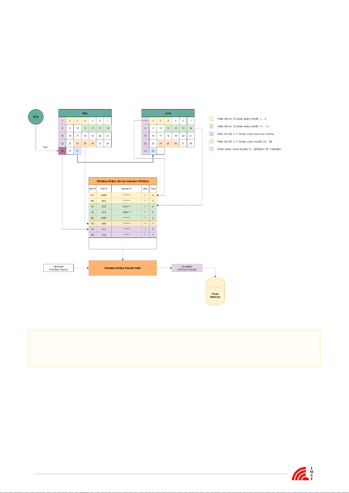
Recording of Wireless M-Bus Packets
Two calendar event types are used to start a Wireless M-Bus packet capture phase either in S-Mode or combined C- / T-Mode. The received
packets will be decoded according to the defined physical layer encoding Manchester, Three Out Of Six or NRZ. Every packet will be
checked for CRC errors and only valid packets will be decoded according to the given frame format A or B. The Wireless M-Bus CRCs are
stripped of to save memory and LoRa upload airtime. In the next step the packet has to pass a filter stage which compares the WM-Bus
packet header fields with a set of configured adresses (Whitelist). Finally the accepted packets are stored into an embedded flash memory.
The flash memory will be automatically erased after each LoRa upload session.
The following figure outlines the connection between WM-Bus reception Calendar Events, Filter Set ID and the Wireless M-Bus Device Filter.
Figure : Example of Wireless M-Bus packet reception, Wireless M-Bus Address Whitelist and Calendar Events
1. It is recommended to reserve some time after a reception phase for uploading of captured messages via LoRaWAN network.®
2. Monthly events which are scheduled for days that are not present in the current month e.g. 29.2, 30.2, 31.2, 31.4, 31.6, 31.9,
31.11 are scheduled for the last day of the month. Thus it is highly recommed not to schedule a Wireless M-Bus capture start or
stop event for one of these days.

Wireless M-Bus Range Extender / / User Manual Version 1.0 Page 15 of 32
Upload of captured Wireless M-Bus Packets
The upload of captured Wireless M-Bus packets can be started by means of a calendar event. Due to the small payload capacity of
LoRaWAN packets a complete Wireless M-Bus packet may require more than one LoRaWAN uplink packet. A reliable upload is ensured® ®
by confirmed LoRaWAN uplink packets and a simple segmentation protocol with minimal overhead of one Byte. The protocol supports®
both, spreading of WM-Bus packets over multiple LoRaWAN® packets and transmitting of multiple WM-Bus packets in a single LoRaWAN®
packet.
Figure : Wireless M-Bus Packet Upload
Every recorded Wireless M-Bus packet is transmitted starting with a 32-Bit UTC timestamp which indicates the time of reception. The
following Wireless M-Bus packet itself starts with an 8-Bit Length-Field which indicates the size of the following message.
Figure: Wireless M-Bus Message Format

Wireless M-Bus Range Extender / / User Manual Version 1.0 Page 16 of 32
Transport Protocol Details
The transport protocol is used in uplink- and downlink direction on several LoRaWAN® ports which indicate the type of message content.
The protocol uses a single octet header field with following format:
Figure : Transport Protocol Header
Last Segment Indicator (Bit 7)
This bit indicates the last segment of a transmission if set to "1".
Segment Number (Bit 0 .. 6)
The segment number starts at zero for every new transmission and will be incremented by "1" for every new segment. On receiver
side it might happen that duplicated segment number will appear. In this case the receiver should simply ignore the duplicate
segments. The segment number can wrap around from 127 to 0 in case of very large transmissions and tiny segments.
The following figure outlines a transmission consisting of four different segments and one re-transmitted segment.
Figure : Example transmission sequence with four segments and one retransmission

Wireless M-Bus Range Extender / / User Manual Version 1.0 Page 17 of 32
Range Extender Status Information
The Range Extender maintains some status information elements which can be transmitted over LoRaWAN or requested via local serial
®
. The transmission can be initiated by means of a calender event.interface
Figure: Range Extender Status Format
The Range Extender Status consists of the following elements:
Range Extender System Time ( from embedded RTC )
Firmware Version
Time of last Synchronization
Reset Counter
Status / Error Bits
Bit 0: LoRaWAN Activation State
®
1 = LoRaWAN Stack is not activated
®
0 = Stack is activated
Bit 1: Network Time Synchronization State
1 = No synchronization via LoRaWAN®
0 = Synchronized via LoRaWAN®
Bit 2: System Time Synchronization State
1 = RTC not synchronized at all
0 = RTC synchronized ( via local serial interface or LoRaWAN )
®
Bit 4: LoRaWAN Configuration State
1 = Configuration is invalid Activation not possible
0 = Configuration is valid
Bit 5: Wireless M-Bus Address Filter List Configuration State
1 = Whitelist is empty no recording possible
0 = Whitelist contains at least one item
Bit 6: Calendar Event List Configuration State
1 = List is empty in this case a default "Get Network Time" event is scheduled every hour at 05:00min for RTC
synchronization
0 = List contains at least one item
Bit 8: Flash Memory Full State
1 = A flash memory full condition has been detected during capture phase this bit will be automatically cleared during the
next recording phase
0 = No error
Bit 9: Flash Memory CRC Error State
1 = A file CRC error has been detected during read & upload operation this bit will be automatically cleared during the next
recording phase
0 = No error
Wireless M-Bus Packet Counters
Number of received packets
Number of filtered and recorded packets
Number of uploaded packets
Note: these counters can be resetted via local serial interface

Wireless M-Bus Range Extender / / User Manual Version 1.0 Page 18 of 32
LED Usage
The Wireless M-Bus Range Extender features a dual color led which is used to signal multiple states and activities. Most of time the Range
Extender will stay in a power saving state in which the led is switched off to save current. Visualization of internal Range Extender firmware
state is done after power-up and can be triggered by means of an magnetic input signal via reed switch.
The following table outlines the Range Extender firmware states and the corresponding led signal:
State Color Timing Action
LoRaWAN stack activated, RTC
®
synchronized, Calendar & Filter
Lists configured
Green 2 x nothing, Range Extender is ready
LoRaWAN stack activated, RTC
®
not synchronized Red 1 x synchronize RTC by means of local
PC Tool or retry via LoRaWAN®
LoRaWAN stack not activated,
®
RTC not synchronized Yellow 2 x activate LoRaWAN stack by
®
means of magnetic input signal on
reed switch
LoRaWAN configuration, Calendar
®
Configuration or WM-Bus Address
Whitelist not valid
Red 3 x connect Range Extender to PC and
start configuration tool for settings
update
The following table outlines the led usage during firmware activities:
Activity Color Timing
Startup Off none
LoRaWAN activation® Red continuously blinking
LoRaWAN Network Time Synchronization® Yellow continuously blinking
LoRaWAN®Network Time Synchronization
successful Green 2 x
LoRaWAN®Network Time Synchronization
failed Red 1 x
Wireless M-Bus capture phase Off none
Wireless M-Bus packet received Green 1 x per packet
Wireless M-Bus packet received but not
accepted by filter stage Yellow 1 x per packet
Wireless M-Bus packet received but not
stored due to memory full condition Red 1 x per packet
Power Saving in Sleep Mode Off none

Wireless M-Bus Range Extender / / User Manual Version 1.0 Page 19 of 32
LoRaWAN® Ports
The LoRaWAN Protocol supports port numbers which are used within this application to identify different kind of messages.
®
LoRaWAN Port
®Message Type
67 ( 0x43 ) Range Extender Status Information
68 ( 0x44 ) Wireless M-Bus Packets

Wireless M-Bus Range Extender / / User Manual Version 1.0 Page 20 of 32
Firmware Update via Bootloader
Main component of the Wireless M-Bus Range Extender is a radio module which comes with an integrated bootloader.
With this bootloader program files ("HEX-Files") can be loaded into the radio modules microcontroller via the Serial Config Interface (UART
pins RxD and TxD).
To enter the bootloader on the Wireless M-Bus Range Extender the jumper has to be set on the BOOT Header and a device reset has to be
carried out, refer to the in step 2.figure
Within the following a step by step instruction how to update the firmware via bootloader is given:
Step 1 : Preparing the PC
Close the WS Configurator if running
Download and install the ( ).STM32CubeProgrammer https://www.st.com/en/development-tools/stm32cubeprog.html
Connect the configuration cable to your and start the STMCubeProg.TTL-232R-3V3 PC
Choose and configure the UART.
Step 2 : Set the Wireless M-Bus Range Extender into Bootloader Mode
Connect the configuration cable TTL-232R-3V3 to the of the Wireless M-Bus Range Extender andSerial Configuration Interface
mount a jumper to the BOOT Header.
Trigger a by pressing the internal reset button or execute a power cycle.Reset
Other manuals for 404600
1
Table of contents
Other IMST Extender manuals


