IMST WiMOD User manual

WiMOD - Demo Board
User Guide
Document ID: 4100/6404/0012
IMST GmbH
Carl-Friedrich-Gauss-Str. 2
D-47475 Kamp-Lintfort
User Guide
WiMOD - Demo Board Summary / Introduction
DemoBoard_UserGuide.doc, Wireless Solutions, V2.4 page 2 of 23
Document Information
File name
DemoBoard_UserGuide
Created
2009-01-15
Total pages
23
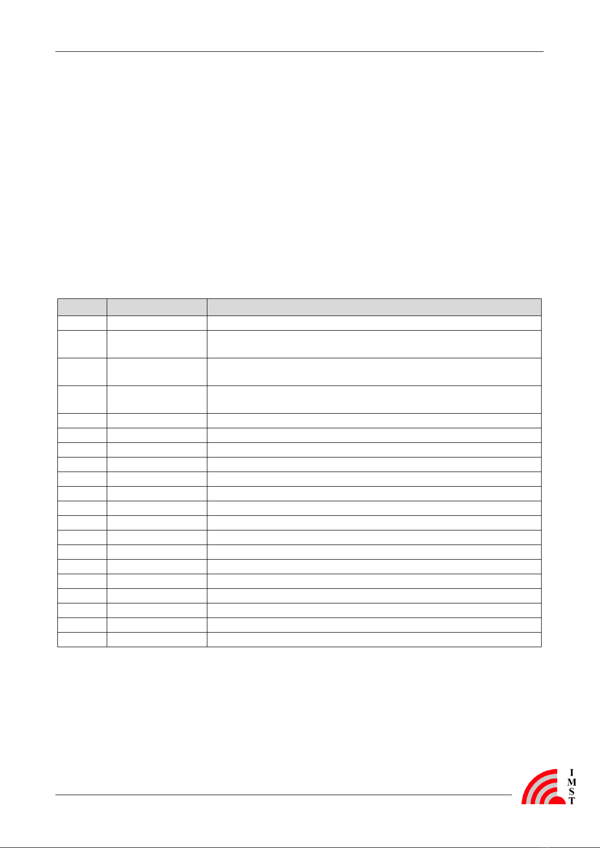
Revision History
Version
Description
1.0
Released version.
1.1
Updated Table 4-2 and Table 4-3 (updated version of AB_02 to 2v0).
1.2
Updated Chapter 4 (added adapter board AB_04 for radio module iM860A).
1.3
Updated Table 4-2 and Table 4-3 (updated version of AB_04 to 1v0, previous version 0v1 is not
supported any more).
1.4
Added information concerning radio module iM871A.
Deleted all sections regarding iM200A
Updated Chapter 4 with a new version of AB_01 (now it supports the iM860A). AB_04 is not
supported any more.
Updated Chapter 5 with schematic version 1.1 (changed values of R20 to R24).
2.0
Added information concerning radio module iM222A.
Updated Chapter 4 with AB_05. Adapter Board “Wireless M-Bus AB 1 v1.0”is not supported any
more.
Modifications to document format and layout.
Added chapter 6, and 7.
2.1
Added current measurement notice
2.2
Added information concerning radio modules iM170A and iM880A.
2.3
Added information concerning radio modules iM880B.
2.4
Added information concerning radio modules iM881A.
Aim of this Document
The aim of this document is to give a detailed product description including interfaces, features
and functionalities of the WiMOD Demo Board.

User Guide
WiMOD - Demo Board Summary / Introduction
DemoBoard_UserGuide.doc, Wireless Solutions, V2.4 page 3 of 23
Table of Contents
1SUMMARY / INTRODUCTION 4
1.1 Key Features 4
1.2 Supported Radio Modules 4
2FUNCTIONAL OVERVIEW 5
2.1 Power Supply 6
2.2 USB Interface 7
2.3 User Interface 7
3CONNECTORS 9
3.1 Radio Module Connector X1and X2 9
3.2 I/O Connector X5, X6 and X7 11
3.3 Programming Connector X3 and X4 13
3.4 Power Connector X8, X9 and X10 14
4ADAPTER BOARD DESCRIPTION 15
5DEMO BOARD DETAILS 18
5.1 Schematic 18
6APPENDIX 20
6.1 List of Abbreviations 20
6.2 List of Figures 21
6.3 List of Tables 21
6.4 References 21
7REGULATORY COMPLIANCE INFORMATION 22
8IMPORTANT NOTICE 23
8.1 Disclaimer 23
8.2 Contact Information 23

User Guide
WiMOD - Demo Board Summary / Introduction
DemoBoard_UserGuide.doc, Wireless Solutions, V2.4 page 4 of 23
1Summary / Introduction
The Demo Board belongs to the product family WiMOD and is part of the WiMOD Starter Kit. It
provides a basic platform for using and testing the WiMOD radio modules together with several
sample applications. Thus it can be used to evaluate all WiMOD radio modules and find out
their capabilities.
1.1 Key Features
- Basic platform for using and testing the different WiMOD radio modules
- USB interface for communication with a PC
- Power supply by USB or battery
- 3 push buttons and 2 DIP switches
- 4 LED indicators
- Temperature sensor with 2-Wire Serial Interface
- Buzzer and potentiometer
- Expansion port (I/O connectors)
1.2 Supported Radio Modules
The Demo Board currently supports the following radio modules:
- iM170A
- iM201A
- iM221A
- iM222A
- iM240A
- iM820A
- iM860A
- iM871A
- iM880A, iM880B
- iM881A
To use one of the radio modules in combination with the Demo Board, the module has to be
soldered on the corresponding Adapter Board (see chapter 4).
User Guide
WiMOD - Demo Board Functional Overview
DemoBoard_UserGuide.doc, Wireless Solutions, V2.4 page 5 of 23
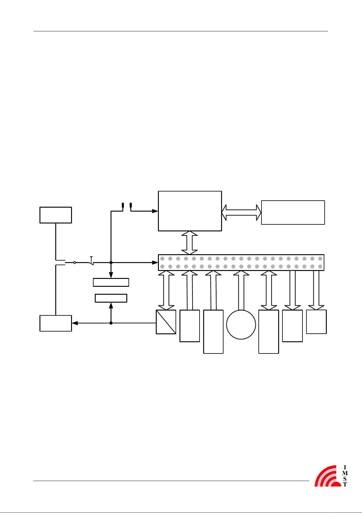
2Functional Overview
The WiMOD Demo Board provides several functional units and can be used to demonstrate
and evaluate the different WiMOD radio modules. The desired radio module must be soldered
on its specific Adapter Board (see chapter 4) which can be plugged on the Demo Board.
All functional units of the Demo Board are shown in Figure 2-1. These are the power supply unit
(via USB or battery), the user interfaces (USB, led, button, buzzer, potentiometer, sensor), the
expansion header (RM connector) for the Adapter Board, and the I/O connectors. The Demo
Board user interfaces and most pins of the attached radio module are made available via the
I/O connectors. Therefore it is possible to connect the radio module to the user interface by
using jumpers or connecting cables. Furthermore it is possible to connect external target boards,
sensors or test equipment to these connectors.
3 Buttons
4 LEDs
Potentio-
meter
Battery
(2xAAA)
Programming
Connectors
RM-Connector
for the
Adapter Board
VCC
VCC
LDO
(3V)
Power LED
USB LED
Buzzer
Reset
(B4)
VCC
selection
(S1)
RM current
measurement
2 DipSwitches
Temperature
sensor
JP1
USB
UART
IO-Connector 1, 2 & 3
Figure 2-1: Block Diagram of the Demo Board
In the following chapters the functional units are described in detail. Figure 2-2 represents the most
important components and their position on the Demo Board. For the schematic of the Demo
Board see chapter 5.1.

User Guide
WiMOD - Demo Board Functional Overview
DemoBoard_UserGuide.doc, Wireless Solutions, V2.4 page 6 of 23
LEDs
D1, D2, D3 & D4
Pin 1 on X7
(I/O Connector 3)
Pin 1 on X5
(I/O Connector 1)
Pin 1 on X4
(Programming
Connector)
Pin 1 on X3
(Programming
Connector)
Pin 1 on X1
(RM Connector 1) LED D5
(USB status)
Jumper
JP1
Push button B4
(RESET)
Sliding switch S1
(Power-Select)
Battery
Connector
Pin 1 on X2
(RM Connector 2)
PotentiometerPush button
B1, B2 & B3
Buzzer
Pin 1 on X6
(I/O Connector 2)
DIP switch
Temperature
sensor
LED D6
(Power status)
Pin 1 on X10
(Aref)
Figure 2-2: Functional Units of the Demo Board
2.1 Power Supply
The Demo Board and the attached radio module may be powered from either two “AAA” size
batteries or from the USB bus when connected to a USB port on a PC. The sliding switch S1
toggles between these power sources and must be switched to the wanted power source. In
position “USB” the USB bus voltage together with a voltage regulator (3 V) is used. In position
“BAT” the battery voltage is used directly. LED 6 is turned on when the Demo Board is powered
on. Additionally LED 5 is turned on if a USB connection to a PC is established. It is
recommended either to use the battery or the USB power, thus S1 can be used as on-off-switch.
To supply the radio module with power jumper JP1 must be set. Furthermore it can be replaced
by an ampere meter to measure the current of the radio module. Note: Some adapter boards
are equipped with a boost converter to increase the radio modules supply voltage (e.g. iM871A
AB_05). In this cases the current measurement has to be done directly on the adapter board.
Power supply of the Demo Board (except the USB interface) and the attached radio module is
interrupted if push button B4 is pressed. Because all radio modules have a Power-On-Reset
(POR) functionality B4 serves as the “RESET”button.
User Guide
WiMOD - Demo Board Functional Overview
DemoBoard_UserGuide.doc, Wireless Solutions, V2.4 page 7 of 23
2.2 USB Interface
The USB interface of the Demo Board can be used for communication between the attached
radio module and a PC. The USB controller (FT232RQ) is turned on once the connection to a
PC is established. This is also signalized by LED 5. The USB interface supports ”USB 1.1“ and
“USB 2.0 full speed“ modes.
The UART interface (TxD, RxD, /CTS, /RTS, /DSR, /DTR, /Ri) of the used USB controller is
available on I/O connector 3 (see chapter 3.2).
Before the USB interface can be used for the first time, the desired hardware driver for the USB
controller must be installed on the PC. If the PC will detect the Demo Board as new hardware
please follow the given instructions to install the new virtual COM port.
For more information see the corresponding website from FTDI [1].
2.3 User Interface
The user interface of the Demo Board provides the following functionalities. Most of them are
available on the I/O connectors (see chapter 3.2).
- USB interface for a serial communication
- LEDs and a buzzer for signal indication
- Buttons and switches for user interaction
- Potentiometer as analog input signal
- Temperature sensor with I²C interface
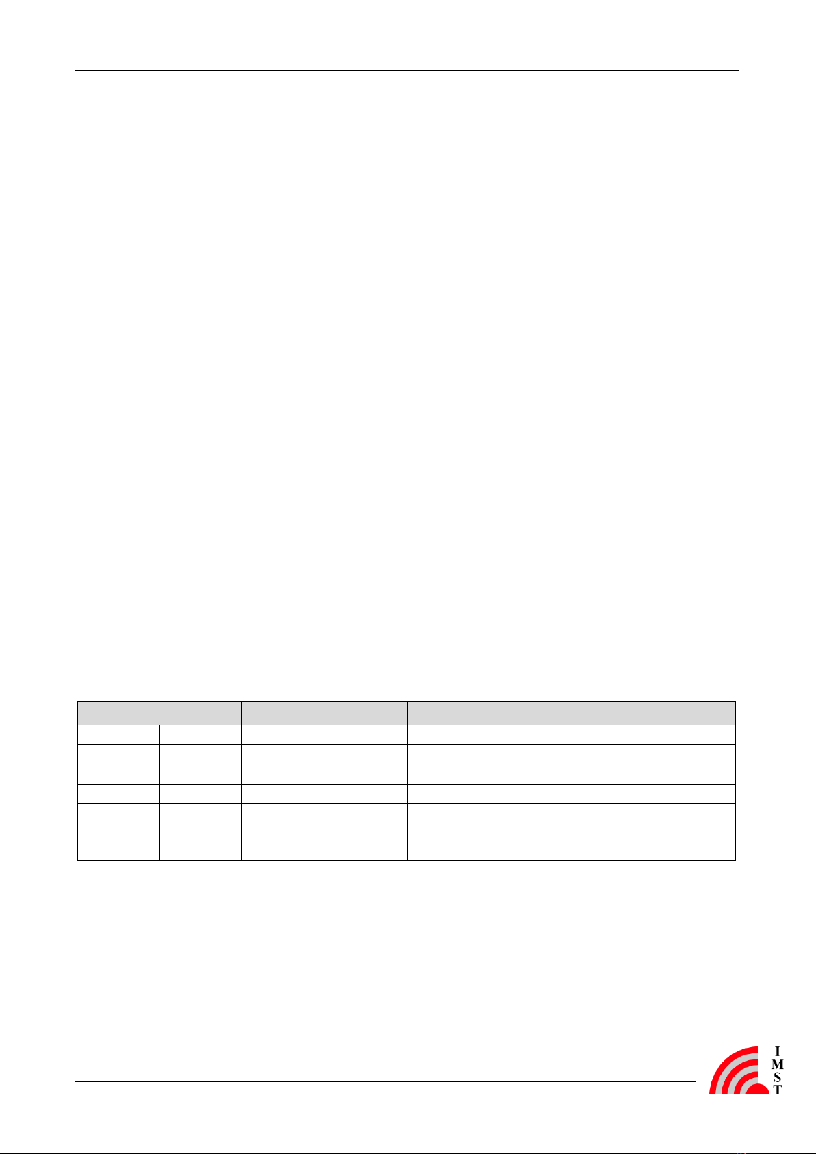
The Demo Board has six LEDs to indicate a status or an event. Table 2-1 explains the LEDs and
to which connector they are connected to.
LED
Available on
Description
D1
red
X5.17 ; X5.19
Useable by the attached radio module.
D2
yellow
X6.3
Useable by the attached radio module.
D3
green
X6.5
Useable by the attached radio module.
D4
orange
X6.7
Useable by the attached radio module.
D5
blue
-
USB status LED, indicating an established USB
connection to a PC.
D6
green
-
Power status LED, indicating when power is switched on
Table 2-1: Connections of the LEDs
LED D5 is turned on if a USB connection to a PC is established. LED D6 indicates the power
supply status. The LEDs D1 to D4 can be connected to the attached radio module by using
jumpers or connecting cables on the I/O connector. They are switched on by a high level signal.
The Demo Board has one sliding switch, four push buttons and two DIP switches. Table 2-2
highlights the functions of these switches and buttons and their availabilities.

User Guide
WiMOD - Demo Board Functional Overview
DemoBoard_UserGuide.doc, Wireless Solutions, V2.4 page 8 of 23
Button/Switch
Available on
Description
S1 –Sliding switch
-
Power select switch.
B1 –Push-Button
X5.7
Useable by the attached radio module.
B2 –Push-Button
X5.9
Useable by the attached radio module.
B3 –Push-Button
X5.1
Useable by the attached radio module.
B4 –Push-Button
-
Power-On-RESET switch (interrupts the power supply).
Dip1_1 –DIP switch 1
X5.3
Useable by the attached radio module.
Dip1_2 –DIP switch 2
X5.15
Useable by the attached radio module.
Table 2-2: Connections of Switches and Buttons
Sliding switch S1 selects the power supply (BAT or USB) and button B4 interrupts the power
supply when pressed.
The push buttons B1 to B3 and the DIP switches Dip1_1 and Dip1_2 can be connected to the
attached radio module by using jumpers or connecting cables on the I/O connectors. All of
them have a pull-up resistor and pushing a button or shifting a DIP switch to position ON causes
the corresponding pin on the I/O connector to be pulled to GND (falling edge) while releasing
will result in a signal with VCC level.
Other units of the Demo Board are explained in Table 2-3. They can be connected to the
attached radio module by using jumpers or connecting cables on the I/O connectors.
Function
Available on
Description
Potentiometer
X5.11
Variable resistor
Buzzer
X5.13
Buzzer
Temperature
Sensor
Thermostat Output
X7.1
Thermostat Output Open Drain of the temperature
sensor (IC4)
Sensor_SDA
X7.5
Data input/output line for 2-Wire serial communication
port of the temperature sensor (IC4)
Sensor_SCL
X7.3
Clock input line for 2-wire serial communication port of
the temperature sensor (IC4).
Table 2-3: Connections of other Functional Units
The potentiometer (trim-pot) provides an analog (voltage) input signal. The value is between
GND and approx. 0.7 V.
The buzzer is a piezoelectric sounder and must be externally driven by a signal. Frequency of this
signal must be between 2 kHz and 4 kHz.
The temperature sensor DS75LX is a digital thermometer and thermostat. It measures
temperatures from -55 °C to +125 °C. Resolution of the digital output signal is 9 to 12 bits.
Communication is achieved through a simple 2-Wire Serial Interface (SDA and SCL).
User Guide
WiMOD - Demo Board Connectors
DemoBoard_UserGuide.doc, Wireless Solutions, V2.4 page 9 of 23
3Connectors
This chapter describes the different connectors of the Demo Board. These are the RM connector
(X1, X2), the I/O connector (X5, X6, X7), the Programming connector (X3, X4) and the Power
connector (X8, X9, X10).
3.1 Radio Module Connector X1and X2
The Radio Module (RM) connector is an expansion header for the Adapter Board and its
soldered radio module. The RM connector consists of the two single row header X1
(RM connector 1) and X2 (RM connector 2). Both have 20 pins and a pin pitch of 2.0 mm.
The pinout of X1 and X2 is explained in Table 3-1 and Table 3-2.
Pin-Nr.
Connected to
Description
X1.1
GND
X1.2
T2.3
/MOSI –inverted programming line of the
RS232 programming interface, which is not supported any longer.
X1.3
T3.6
/SCK –inverted clock line of the
RS232 programming interface, which is not supported any longer.
X1.4
T2.6
/CS –inverted chip select line of the
RS232 programming interface which is not supported any longer.
X1.5
X4.9
MOSI –programming line for ISP
X1.6
X4.8
DC –clock line for the Debug Interface
X1.7
X4.6
/RESET –/RESET line or programming line for DebugWIRE
X1.8
GND
X1.9
X4.5
DD –data line for the Debug Interface
X1.10
X4.3
MISO –programming line for ISP
X1.11
X4.1
SCK –clock line for ISP
X1.12
X5.14
Connected to I/O connector 1
X1.13
GND
X1.14
X5.12
Connected to I/O connector 1
X1.15
X5.10
Connected to I/O connector 1
X1.16
X5.8
Connected to I/O connector 1
X1.17
X5.6
Connected to I/O connector 1
X1.18
X5.4
Connected to I/O connector 1
X1.19
X5.2
Connected to I/O connector 1
X1.20
GND
Table 3-1: Pinout of X1
The pins X1.2, X1.3, and X1.4 are connected to the RS232 programming interface which is not
supported any longer. The pins X1.5, X1.6, X1.7, X1.9, X1.10 and X1.11 are connected to X4
which can be used for programming the WiMOD radio modules. All other pins of X1 are
connected to GND or to I/O connector 1.
User Guide
WiMOD - Demo Board Connectors
DemoBoard_UserGuide.doc, Wireless Solutions, V2.4 page 10 of 23
Pin-Nr.
Connected to
Description
X2.1
GND
X2.2
X5.16
Connected to I/O connector 1
X2.3
X5.18
Connected to I/O connector 1
X2.4
X5.20
Connected to I/O connector 1
X2.5
X6.4
Connected to I/O connector 2
X2.6
X6.6
Connected to I/O connector 2
X2.7
X6.8
Connected to I/O connector 2
X2.8
X7.2
Connected to I/O connector 3
X2.9
X7.4
Connected to I/O connector 3
X2.10
GND
X2.11
X7.6
Connected to I/O connector 3
X2.12
X7.8
Connected to I/O connector 3
X2.13
X7.10
Connected to I/O connector 3
X2.14
X7.12
Connected to I/O connector 3
X2.15
X7.14
Connected to I/O connector 3
X2.16
X7.16
Connected to I/O connector 3
X2.17
X7.18
Connected to I/O connector 3
X2.18
X7.20
Connected to I/O connector 3
X2.19
GND
X2.20
VCC_RM
Power supply for the radio module
Table 3-2: Pinout of X2
All pins of X2 are connected to I/O connector 2 and 3 or have to be used for power supply
(GND or VCC) of the radio module.
User Guide
WiMOD - Demo Board Connectors
DemoBoard_UserGuide.doc, Wireless Solutions, V2.4 page 11 of 23
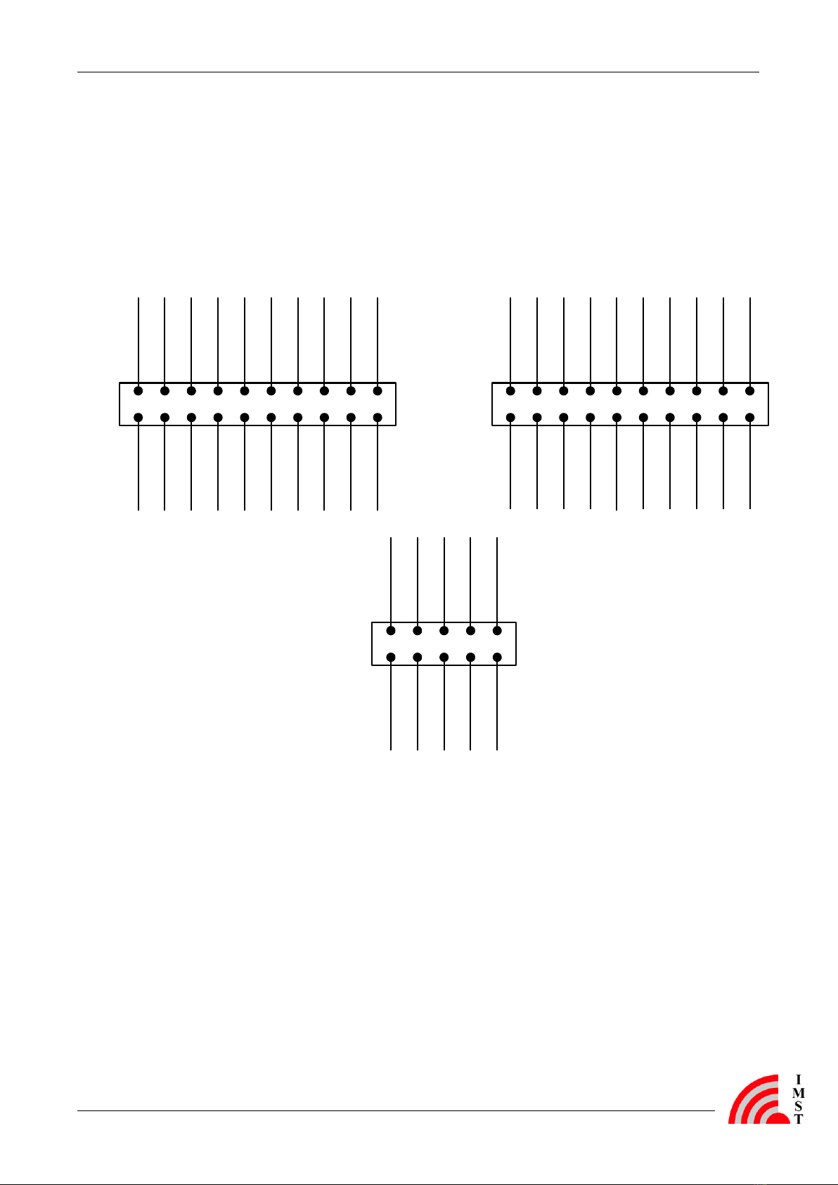
3.2 I/O Connector X5, X6 and X7
The I/O connector consists of the three pin rows X5 (I/O connector 1), X6 (I/O connector 2) and
X7 (I/O connector 3). On the one side (odd pin numbers) they are connected to the user
interface of the Demo Board. On the other side (even pin numbers) they are connected to the
attached radio module via RM connector 1 and 2. Thus it is possible to connect the radio
module to the user interface by using jumpers or connecting cables. Figure 3-1 depicts the
pinout of the I/O connector.
Button 3 1
Dip Switch 1 3
Ext. Aref 5
Button 1 7
Button 2 9
Poti 11
Buzzer 13
Dip Switch 2 15
LED 1 17
LED 1 19
X1.19
2
X1.18
4
X1.17
6
X1.16
8
X1.15
10
X1.14
12
X1.12
14
X2.2
16
X2.3
18
X2.4
20
Thermostat
Output 1
Sensor_SCL 3
Sensor_SDA 5
/CTS_USB 7
/DSR_USB 9
/RI_USB 11
RxD_USB 13
/RTS_USB 15
/DTR_USB 17
TxD_USB 19
X2.8
2
X2.9
4
X2.11
6
X2.12
8
X2.13
10
X2.14
12
X2.15
14
X2.16
16
X2.17
18
X2.18
20
GND 1
LED 2 3
LED 3 5
LED 4 7
GND 9
GND
2
X2.5
4
X2.6
6
X2.7
8
GND
10
X5
X6
X7
Figure 3-1: Graphical Pinout of the I/O connector
Moreover Table 3-3, Table 3-4, and Table 3-5 explain the pin assignment of the I/O connector.
User Guide
WiMOD - Demo Board Connectors
DemoBoard_UserGuide.doc, Wireless Solutions, V2.4 page 12 of 23
Pin-Nr.
Connected to
Pin-Nr.
Connected to
X5.1
Button 3
X5.2
X1.19
X5.3
DIP Switch 1
X5.4
X1.18
X5.5
Ext. Aref
X5.6
X1.17
X5.7
Button 1
X5.8
X1.16
X5.9
Button 2
X5.10
X1.15
X5.11
Potentiometer (0 –approx. 0.7V)
X5.12
X1.14
X5.13
Buzzer
X5.14
X1.12
X5.15
DIP Switch 2
X5.16
X2.2
X5.17
LED 1
X5.18
X2.3
X5.19
LED 1
X5.20
X2.4
Table 3-3: Pinout of X5 (I/O connector 1)
Pin-Nr.
Connected to
Pin-Nr.
Connected to
X6.1
GND
X6.2
GND
X6.3
LED 2
X6.4
X2.5
X6.5
LED 3
X6.6
X2.6
X6.7
LED 4
X6.8
X2.7
X6.9
GND
X6.10
GND
Table 3-4: Pinout of X6 (/IO connector 2)
Pin-Nr.
Connected to
Pin-Nr.
Connected to
X7.1
Thermostat Output
X7.2
X2.8
X7.3
Temperature sensor (Sensor_SCL)
X7.4
X2.9
X7.5
Temperature sensor (Sensor_SDA)
X7.6
X2.11
X7.7
IC2.8 –/CTS of the USB Controller
X7.8
X2.12
X7.9
IC2.6 –/DSR of the USB-Controller
X7.10
X2.13
X7.11
IC2.3 –/RI of the USB-Controller
X7.12
X2.14
X7.13
IC2.2 –RxD of the USB-Controller
X7.14
X2.15
X7.15
IC2.32 –/RTS of the USB-Controller
X7.16
X2.16
X7.17
IC2.31 –/DTR of the USB-Controller
X7.18
X2.17
X7.19
IC2.30 –TxD of the USB-Controller
X7.20
X2.18
Table 3-5: Pinout of X7 (I/O connector 3)
User Guide
WiMOD - Demo Board Connectors
DemoBoard_UserGuide.doc, Wireless Solutions, V2.4 page 13 of 23
3.3 Programming Connector X3 and X4
All modules can be reprogrammed either by using the integrated programming interface or the
integrated bootloader via UART interface. On the Demo Board the UART has to be connected to
the USB interface on X7. Alternatively the integrated programming interface of the module can
be used to flash a new program into the module.
Connector X4 can be used to connect a programming device for all WiMOD radio modules
(except iM871A which has to be programmed via the programming connector on its Adapter
Board “Wireless M-Bus AB 1”). The necessary programming device depends on the connected
radio module. Table 3-6 shows the pinout of X4.
Pin-Nr.
Connected to
Description
X4.1
X1.11
SCK –clock line for ISP
X4.2
GND
X4.3
X1.10
MISO –data line for ISP (to the programming device)
X4.4
VCC
Reference voltage for the programming device. Must not be used to
power the Demo Board and the attached radio module.
X4.5
X1.9
DD –data line for the Debug Interface
X4.6
X1.7
/RESET –Reset line for ISP or data line for DebugWIRE
X4.7
NC
Not connected
X4.8
X1.6
DC –clock line for the Debug Interface
X4.9
X1.5
MOSI –data line for ISP (to the radio module)
X4.10
GND
Table 3-6: : Pinout of X4 ( ISP, DebugWIRE, DebugInterface)
Warning: It cannot be guaranteed, that the chosen programming
device can be connected one-to-one to programming connector
X4. Contact us for further information.
Warning: The bootloader will be deleted if the integrated
programming interface is used. It is not possible to update the
modules firmware with the corresponding PC tool if the bootloader
has been deleted.
User Guide
WiMOD - Demo Board Connectors
DemoBoard_UserGuide.doc, Wireless Solutions, V2.4 page 14 of 23
3.4 Power Connector X8, X9 and X10
The connectors X8, X9, and X10 can be used for voltage measurement or to connect an external
voltage supply. Voltage of the radio module can be measured on X9. X8 can be used to connect
an external voltage (max. 3.6V) instead of the two batteries. For detailed information see the
schematic in chapter 5.1. X10 serves as analog reference voltage for the A/D converter of the
attached radio module. The usable reference voltage value depends on the used radio module
(see the appropriate datasheet).
Warning: Please do not connect a jumper to one of the power
connectors. This would cause a short-circuit and could damage the
Demo Board and the attached radio module.
User Guide
WiMOD - Demo Board Adapter Board Description
DemoBoard_UserGuide.doc, Wireless Solutions, V2.4 page 15 of 23
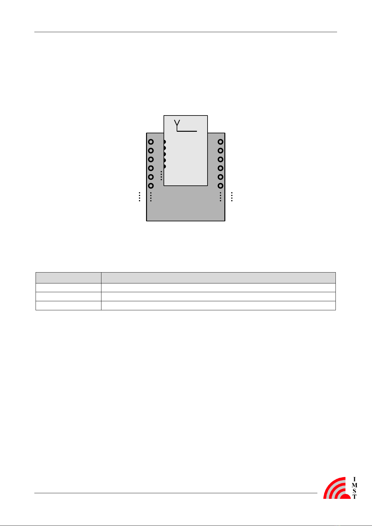
4Adapter Board Description
For using a radio module with the Demo Board and it features, a specific Adapter Board is
necessary. It is a carrier board for the radio module which has to be plugged on the
RM connector (X1 and X2) of the Demo Board. Figure 4-1 shows an Adapter Board with a
soldered radio module.
X1.1
X1.2
X1.3
X1.4
X1.5
X1.6
X2.1
X2.2
X2.3
X2.4
X2.5
X2.6
Adapter Board
Radio
Module
1
2
3
4
5
Figure 4-1: Adapter Board with Soldered Radio Module
There are several Adapter Boards for the different radio modules. Table 4-1 explains which
radio modules are supported. AB_03 and AB_04 are not supported any more.
Adapter Board
Supported Radio Modules
AB_01
iM201A, iM240A, iM860A, iM170A, iM880A, iM880B, iM881A
AB_02
iM820A, iM221A, iM222A
AB_05
iM871A
Table 4-1: Assignment between WiMOD Modules and Adapter Boards
The following tables (Table 4-2 and Table 4-3) explain the pin assignment of the Adapter
Boards respectively the pin assignment of the RM connector (X1 and X2) if the Adapter Board is
plugged on the Demo Board. The “Pad Nr.” relates to the pads of the soldered radio module.
All Adapter Boards consist of a SMA connector which is connected to the 50 pad of the radio
module. It can be used for connecting RF measurement equipment or an external antenna. In
this case the RF path of a radio module has to be switched to the 50 pad instead of using the
integrated PCB antenna.

User Guide
WiMOD - Demo Board Adapter Board Description
DemoBoard_UserGuide.doc, Wireless Solutions, V2.4 page 16 of 23
X1
AB_01 v2.0
AB_02 v3.0
AB_05 v2.0
Radio module Pad Nr.
Radio module Pad Nr.
Radio module Pad Nr.
X1.1
1/6/11/16/22/
27/30/32
(GND)
(1/3/4/8/12/16/18/
19/24/29/33/34
(GND)
5/15/17/24/28
(GND)
X1.2
-
-
-
X1.3
-
-
-
X1.4
-
-
-
X1.5
3
-
-
X1.6
-
32
-
X1.7
7
5Note 1
25
X1.8
1/6/11/16/22/
27/30/32
(GND)
(1/3/4/8/12/16/18/
19/24/29/33/34
(GND)
5/15/17/24/28
(GND)
X1.9
2
31
-
X1.10
4
-
-
X1.11
5
-
26
X1.12
8
13
-
X1.13
1/6/11/16/22/
27/30/32
(GND)
(1/3/4/8/12/16/18/
19/24/29/33/34
(GND)
5/15/17/24/28
(GND)
X1.14
9
20
-
X1.15
12
7
27
X1.16
13
9
4
X1.17
10
28
11
X1.18
15
10
2
X1.19
14
11
14
X1.20
1/6/11/16/22/
27/30/32
(GND)
(1/3/4/8/12/16/18/
19/24/29/33/34
(GND)
5/15/17/24/28
(GND)
Notes:
1) There is a RC-filter (1kwith 2,7nF) on this line.
Table 4-2: Pinout of X1 with Connected Adapter Board

User Guide
WiMOD - Demo Board Adapter Board Description
DemoBoard_UserGuide.doc, Wireless Solutions, V2.4 page 17 of 23
X2
AB_01 v2.0
AB_02 v3.0
AB_05 v2.0
Radio module Pad Nr.
Radio module Pad Nr.
Radio module Pad Nr.
X2.1
1/6/11/16/22/
27/30/32
(GND)
(1/3/4/8/12/16/18/
19/24/29/33/34
(GND)
5/15/17/24/28
(GND)
X2.2
29Note 2
6
-
X2.3
29Note 2
6
-
X2.4
26Note 2
-
1
X2.5
25
30
3
X2.6
24
27
6
X2.7
20
21
7
X2.8
28Note 1 (GND)
-
-
X2.9
21
15
8
X2.10
1/6/11/16/22/
27/30/32
(GND)
(1/3/4/8/12/16/18/
19/24/29/33/34
(GND)
5/15/17/24/28
(GND)
X2.11
23
14
9
X2.12
-
26
-
X2.13
-
-
-
X2.14
-
-
-
X2.15
19
23
19
X2.16
-
25
13
X2.17
-
-
12
X2.18
18
22
18
X2.19
1/6/11/16/22/
27/30/32
(GND)
(1/3/4/8/12/16/18/
19/24/29/33/34
(GND)
5/15/17/24/28
(GND)
X2.20
17 (VCC)
17 (VCC)
29 (VCC=3V) Note 3
Notes:
1) Pad 28 of the radio module iM240A is internally connected to GND. Thus X2.8 respectively X7.2 of the Demo
Board must not be used when using the iM240A.
2) Pad 26 and pad 29 are reserved at the iM240A and should not be connected when using this radio module.
3) The radio module is powered by an additional boost converter on the Adapter Board.
Table 4-3: Pinout of X2 with Connected Adapter Board

User Guide
WiMOD - Demo Board Demo Board Details
DemoBoard_UserGuide.doc, Wireless Solutions, V2.4 page 18 of 23
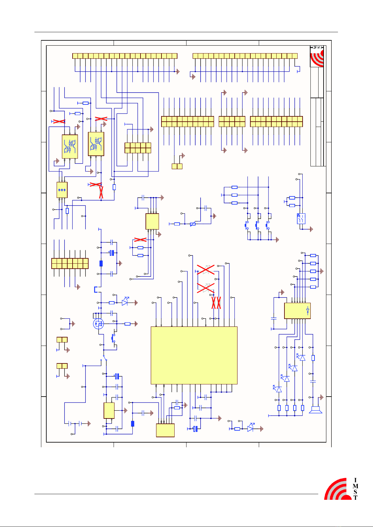
5Demo Board Details
5.1 Schematic
1
1
2
2
3
3
4
4
5
5
6
6
7
7
8
8
D D
C C
B B
A A
WiMOD_DB.SchDocFile:
Date: 03.11.2009 Time: 16:44:39
Number:1Revision:1.0 Sheet 1of 1
Title: WiMOD - DemoBoard Carl-Friedrich-Gauss-Str.2
47475 Kamp-Lintfort
http://www.imst.de
http://www.wire less-so lution s.d e
IMSTGmbH
Designer:MB
-standardVariant:
1 3
2 4
B4
RESET
1 3
2 4
B3 User_Button 3
1 3
2 4
B1 User_Button 1
1
3
2S1
Power-Select
SP1
1 3
2
R8
10k
1
10
2
9
3
8
4
7
5
6
12
11
13
14
15
16
17
18
19
20
X1
FMHeader 1
1
10
2
9
3
8
4
7
5
6
12
11
13
14
15
16
17
18
19
20
X2
FMHeader 2
VCC
/CS
/MOSI
SCK
MISO
DD
MOSI
/RESET
DC
/CS
MISO
MOSI
DD
DC
/RESET
1 3
2 4
B2 User_Button 2
VCC_REGUSB5V
USB5V
VCC
C6
100n
C2
10n
C4
100n
C5
100n
C7
100n C9
2u2
L1
BLM18PG300S
C3
10u/10V
C10
10u
C1
10n
R1
1M
IN
GND
EN NR
OUT
IC1
TPS73030
C8
10n
R5
10k
C12
10n
VCC
C13
2u2
VCC_FM
VCC
R12
390
R13
390
R14
390
R15
390
C15
100n
VCC
C16
100n
R18
1k2
1A 1
1Y
22A 3
2Y
43A 5
3Y
6
GND 7
5Y
10 4A 9
6Y
12 5A 11
VCC
14
6A 13
4Y
8
IC3
SN74LVC04AD
R9
47k R10
47k R11
47k
VCC
TxD_USB
RxD_USB
/RTS_USB
/CTS_USB
/RI_USB
R17
NC
R6
390
CurrentMeasurement
JP1
JUMPER
LED1
LED2
LED3
LED4
Buzzer
Button1
Button2
V_BAT
VCC
R7
33k
C17
1u
Poti
/DTR_USB
/DSR_USB
VCC_FM
R16
NC
R2
390
3V3_USB
3V3_USB
CBUS2_USB
CBUS3_USB
CBUS4_USB
X1_12
X1_14
X1_15
X1_16
X1_17
X1_18
X1_19
X2_2
X2_3
X2_4
X2_5
X2_6
X2_7
X2_9
X2_8
X2_11
X2_12
X2_14
X2_15
X2_16
X2_17
X2_18
X2_13
1 2
3 4
5 6
7 8
9 10
X4
ISP/DebugWIRE
X1_12
X1_14
X1_15
X1_16
X1_17
X1_18
X1_19
X2_2
X2_3
X2_4
X2_5
X2_6
X2_7
X2_9
X2_8
X2_11
X2_12
X2_14
X2_15
X2_16
X2_17
X2_18
Button2
Button1
TxD_USB
RxD_USB
Button3
LED1
LED2
/RTS_USB
/RI_USB
/SCK
SCK
L2
BLM18PG300S
C14
10u
D5
blau
Power
D6
gruen
D4
orange D3
gruen D2
gelb D1
rot
/TX_LED
D7
NC /RX_LED
D8
NC
V_IN 1
D- 2
D+ 3
GND 4
SHLD 5
SHLD 6
J1
USB-BW
Shield
VCCIO
1
VCC
19
USBD-
15
USBD+
14
/RESET 18
OSCI
27
OSCO
28
TEST
26
AGND
24
GND
4
GND
17
GND
20
Exposed Pad
0
TxD 30
RxD 2
/RTS 32
/CTS 8
/DTR 31
/DSR 6
/DCD 7
/RI 3
CBUS0 22
CBUS1 21
CBUS2 10
CBUS3 11
CBUS4 9
3V3OUT
16
IC2
FT232RQ
X2_13
C19
100n
Poti
Buzzer
LED4
LED3
1
2
X8
V_BAT
1
2
X9
VCC_FM
VCC_FM
TP75
VCC_REG
TP76
GND
TP30
CBUS2_USB
TP31
CBUS3_USB
TP21
/DTR_USB TP22
/DSR_USB
TP25
/RESET_USB
TP23
/DCD_USB
TP1
V_IN_USB
TP2
USB_5V
TP3
VBat
TP4
VCC_Reg
TP5
B4_IN
TP6
VCC
TP7
L2_IN
TP8
L2_OUT
TP9
GND
TP10
B4_OUT
TP11
D6
TP13
USBDM
TP14
USBDP
TP15
3V3
TP16
D5
TP17
TxD_USB
TP18
TESTPIN
TP19
/RTS_USB
TP20
/CTS_USB
TP24
/RI
TP26
CBUS0
TP27
CBUS1
TP28
D7
TP29
D8
TP32
CBUS4_USB
TP37
Buzzer
TP33
LED4
TP34
LED3
TP35
LED2
TP36
LED1
TP38
IC3_10
TP39
IC3_8
TP40
IC3_6
TP41
IC3_4
TP42
IC3_2
TP43
D4
TP44
D3
TP45
D2
TP46
D1
TP47
C16_IN
TP48
C16_OUT
TP49
PB_2
TP50
PB_1
TP51
PB_3
TP52
R8_IN
TP53
R8_OUT
3V3_USB
R20
47k R21
47k R22
47k R23
47k R24
47k
1.5V/AAA
1.5V/AAA
1
24
3
Dip1
R25
47k R26
47k
VCC
DipSwitch1
DipSwitch2
C20
100n
VCC
R27
10k R28
10k R29
NC/10k
VCC
Sensor_SDA
Sensor_SCL
ThermostatOutput SDA
1VCC 8
SCL
2A0 7
O.S.
3A1 6
GND
4A5 5
IC4 DS75LXU+
1
3
46
2
5
T1
BSV236 SP
E1
1C1 6
B1
2B2 5
C2
3E2 4
R2
R1
R1
R2
T2
PUMH11
E1
1C1 6
B1
2B2 5
C2
3E2 4
R2
R1
R1
R2
T3 PUMH11
A1
1K1 6
A2
2K2 5
A3
3K3 4
D20
BAS16VY
RS232_DTR
RS232_RTS
RS232_CTS
RS232_DSR
RS232_TxD
R40
NC / 470
R41
470
R42
470
VCC
VCC
VCC
DipSwitch1
DipSwitch2
Sensor_SDA
Sensor_SCL
ThermostatOutput
/MOSI
/SCK
R43
0
/DTR_USB
/DSR_USB
R44
NC
VCC
Button3
R45
NC
R46
NC
R47
0
V_BAT
1 2
3 4
5 6
7 8
9 10
X6
IO_Connector 2
1 2
3 4
5 6
7 8
9 10
11 12
13 14
15 16
17 18
19 20
X5
IO_Connector 1
1 2
3 4
5 6
7 8
9 10
11 12
13 14
15 16
17 18
19 20
X7
IO_Connector 3
/CTS_USB
LED1
TP54
Dip1TP55
Dip2
TP56
SDA
TP57
SCL
TP58
O.S.
TP60
D20_2
TP61
D20_3
TP65
T2_3
TP67
T3_6
TP68
X3_8
TP69
T3_3
TP70
X4_3
TP66
T2_6
TP78 RS232_DTR
RS232_RTS
RS232_CTS
RS232_DSR
RS232_TxD
1 2
3 4
5 6
7 8
9 10
11 12
13 14
X3
RS232 for PonyProg
1
2
X10
ext.Aref
Figure 5-1: Schematic version 1.0 of the Demo Board
User Guide
WiMOD - Demo Board Demo Board Details
DemoBoard_UserGuide.doc, Wireless Solutions, V2.4 page 19 of 23
1
1
2
2
3
3
4
4
5
5
6
6
7
7
8
8
D D
C C
B B
A A
WiMOD_DB.SchDocFile:
Date: 19.11.2010 Time: 10:20:26
Number:1Revision:1.1 Sheet 1of 1
Title: WiMOD - DemoBoard Carl-Friedrich-Gauss-Str.2
47475 Kamp-Lintfort
http://www.imst.de
http://www.wireless-solutions.de
IMSTGmbH
Designer:MB
-standardVariant:
1 3
2 4
B4
RESET
1 3
2 4
B3 User_Button 3
1 3
2 4
B1 User_Button 1
1
3
2S1
Power-Select
SP1
1 3
2
R8
10k
1
10
2
9
3
8
4
7
5
6
12
11
13
14
15
16
17
18
19
20
X1
FMHeader 1
1
10
2
9
3
8
4
7
5
6
12
11
13
14
15
16
17
18
19
20
X2
FMHeader 2
VCC
/CS
/MOSI
SCK
MISO
DD
MOSI
/RESET
DC
/CS
MISO
MOSI
DD
DC
/RESET
1 3
2 4
B2 User_Button 2
VCC_REGUSB5V
USB5V
VCC
C6
100n
C2
10n
C4
100n
C5
100n
C7
100n C9
2u2
L1
BLM18PG300S
C3
10u/10V
C10
10u
C1
10n
R1
1M
IN
GND
EN NR
OUT
IC1
TPS73030
C8
10n
R5
10k
C12
10n
VCC
C13
2u2
VCC_FM
VCC
R12
390
R13
390
R14
390
R15
390
C15
100n
VCC
C16
100n
R18
1k2
1A 1
1Y
22A 3
2Y
43A 5
3Y
6
GND 7
5Y
10 4A 9
6Y
12 5A 11
VCC
14
6A 13
4Y
8
IC3
SN74LVC04AD
R9
47k R10
47k R11
47k
VCC
TxD_USB
RxD_USB
/RTS_USB
/CTS_USB
/RI_USB
R17
NC
R6
390
CurrentMeasurement
JP1
JUMPER
LED1
LED2
LED3
LED4
Buzzer
Button1
Button2
V_BAT
VCC
R7
33k
C17
1u
Poti
/DTR_USB
/DSR_USB
VCC_FM
R16
NC
R2
820
3V3_USB
3V3_USB
CBUS2_USB
CBUS3_USB
CBUS4_USB
X1_12
X1_14
X1_15
X1_16
X1_17
X1_18
X1_19
X2_2
X2_3
X2_4
X2_5
X2_6
X2_7
X2_9
X2_8
X2_11
X2_12
X2_14
X2_15
X2_16
X2_17
X2_18
X2_13
1 2
3 4
5 6
7 8
9 10
X4
ISP/DebugWIRE
X1_12
X1_14
X1_15
X1_16
X1_17
X1_18
X1_19
X2_2
X2_3
X2_4
X2_5
X2_6
X2_7
X2_9
X2_8
X2_11
X2_12
X2_14
X2_15
X2_16
X2_17
X2_18
Button2
Button1
TxD_USB
RxD_USB
Button3
LED1
LED2
/RTS_USB
/RI_USB
/SCK
SCK
L2
BLM18PG300S
C14
10u
D5
blau
Power
D6
gruen
D4
orange D3
gruen D2
gelb D1
rot
/TX_LED
D7
NC /RX_LED
D8
NC
V_IN 1
D- 2
D+ 3
GND 4
SHLD 5
SHLD 6
J1
USB-BW
Shield
VCCIO
1
VCC
19
USBD-
15
USBD+
14
/RESET 18
OSCI
27
OSCO
28
TEST
26
AGND
24
GND
4
GND
17
GND
20
Exposed Pad
0
TxD 30
RxD 2
/RTS 32
/CTS 8
/DTR 31
/DSR 6
/DCD 7
/RI 3
CBUS0 22
CBUS1 21
CBUS2 10
CBUS3 11
CBUS4 9
3V3OUT
16
IC2
FT232RQ
X2_13
C19
100n
Poti
Buzzer
LED4
LED3
1
2
X8
V_BAT
1
2
X9
VCC_FM
VCC_FM
TP75
VCC_REG
TP76
GND
TP30
CBUS2_USB
TP31
CBUS3_USB
TP21
/DTR_USB TP22
/DSR_USB
TP25
/RESET_USB
TP23
/DCD_USB
TP1
V_IN_USB
TP2
USB_5V
TP3
VBat
TP4
VCC_Reg
TP5
B4_IN
TP6
VCC
TP7
L2_IN
TP8
L2_OUT
TP9
GND
TP10
B4_OUT
TP11
D6
TP13
USBDM
TP14
USBDP
TP15
3V3
TP16
D5
TP17
TxD_USB
TP18
TESTPIN
TP19
/RTS_USB
TP20
/CTS_USB
TP24
/RI
TP26
CBUS0
TP27
CBUS1
TP28
D7
TP29
D8
TP32
CBUS4_USB
TP37
Buzzer
TP33
LED4
TP34
LED3
TP35
LED2
TP36
LED1
TP38
IC3_10
TP39
IC3_8
TP40
IC3_6
TP41
IC3_4
TP42
IC3_2
TP43
D4
TP44
D3
TP45
D2
TP46
D1
TP47
C16_IN
TP48
C16_OUT
TP49
PB_2
TP50
PB_1
TP51
PB_3
TP52
R8_IN
TP53
R8_OUT
3V3_USB
R20
4k7 R21
4k7 R22
4k7 R23
4k7 R24
4k7
1.5V/AAA
1.5V/AAA
1
24
3
Dip1
R25
47k R26
47k
VCC
DipSwitch1
DipSwitch2
C20
100n
VCC
R27
10k R28
10k R29
NC/10k
VCC
Sensor_SDA
Sensor_SCL
ThermostatOutput SDA
1VCC 8
SCL
2A0 7
O.S.
3A1 6
GND
4A5 5
IC4 DS75LXU+
1
3
46
2
5
T1
BSV236 SP
E1
1C1 6
B1
2B2 5
C2
3E2 4
R2
R1
R1
R2
T2
PUMH11
E1
1C1 6
B1
2B2 5
C2
3E2 4
R2
R1
R1
R2
T3 PUMH11
A1
1K1 6
A2
2K2 5
A3
3K3 4
D20
BAS16VY
RS232_DTR
RS232_RTS
RS232_CTS
RS232_DSR
RS232_TxD
R40
NC / 470
R41
470
R42
470
VCC
VCC
VCC
DipSwitch1
DipSwitch2
Sensor_SDA
Sensor_SCL
ThermostatOutput
/MOSI
/SCK
R43
0
/DTR_USB
/DSR_USB
R44
NC
VCC
Button3
R45
NC
R46
NC
R47
0
V_BAT
1 2
3 4
5 6
7 8
9 10
X6
IO_Connector 2
1 2
3 4
5 6
7 8
9 10
11 12
13 14
15 16
17 18
19 20
X5
IO_Connector 1
1 2
3 4
5 6
7 8
9 10
11 12
13 14
15 16
17 18
19 20
X7
IO_Connector 3
/CTS_USB
LED1
TP54
Dip1TP55
Dip2
TP56
SDA
TP57
SCL
TP58
O.S.
TP60
D20_2
TP61
D20_3
TP65
T2_3
TP67
T3_6
TP68
X3_8
TP69
T3_3
TP70
X4_3
TP66
T2_6
TP78 RS232_DTR
RS232_RTS
RS232_CTS
RS232_DSR
RS232_TxD
1 2
3 4
5 6
7 8
9 10
11 12
13 14
X3
RS232 for PonyProg
1
2
X10
ext.Aref
Figure 5-2: Schematic version 1.1 of the Demo Board

User Guide
WiMOD - Demo Board Appendix
DemoBoard_UserGuide.doc, Wireless Solutions, V2.4 page 20 of 23
6Appendix
6.1 List of Abbreviations
AB = Adapter Board
ADC = Analog-to-Digital Converter
DB = Demo Board
DIO = Digital Input/Output
GPIO = General Purpose Input/Output
IEEE = Institute of Electrical and Electronics Engineers
I²C = Inter-Integrated Circuit
LDO = Low Drop-Out voltage regulator
MCU = Microcontroller Unit
PCB = Printed Circuit Board
POR = Power-On Reset
RAM = Random Access Memory
RF = Radio Frequency
RM = Radio Module
SPI = Serial Peripheral interface
UART = Universal Asynchronous Receiver/Transmitter
USB = Universal Serial Bus
Table of contents


