ChapterChapter
11
System Board
System Board 1-1
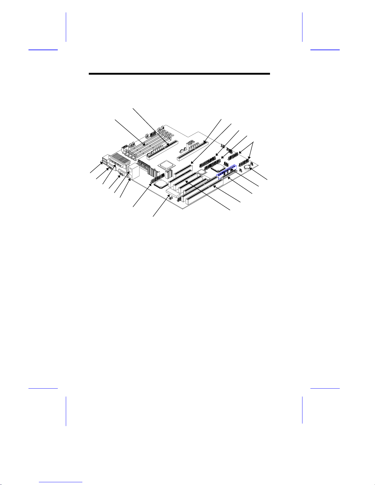
1.1 Features
This high-performance system board supports the Intel Pentium II CPU
running at 233/266/300 MHz. Designed to work with Intel 440LX system
controller, which consists of the PCI/AGP controller (PAC) and the PCI/ISA
IDE accelerator (PIIX4), the CPU carries a new generation of power.
The PAC host bus interface supports up to two Pentium II processors with
66 MHz bus frequency. It also provides a 72-bit DRAM support using both
extended data output (EDO) and synchronous DRAM (SDRAM) DIMMs.
The PAC introduces a new technology, which is the Accelerated Graphics
Port (AGP) interface. Supporting up to 133 MHz data transfer rate, the
AGP interface boosts graphics performance.
The PIIX4 is a multifunction PCI device controller implementing system
functions including PCI-to-PCI bridge, PCI IDE, universal serial bus (USB)
host/hub, and enhance power management. It also supports Ultra DMA/33
synchronous DMA-compatible devices.
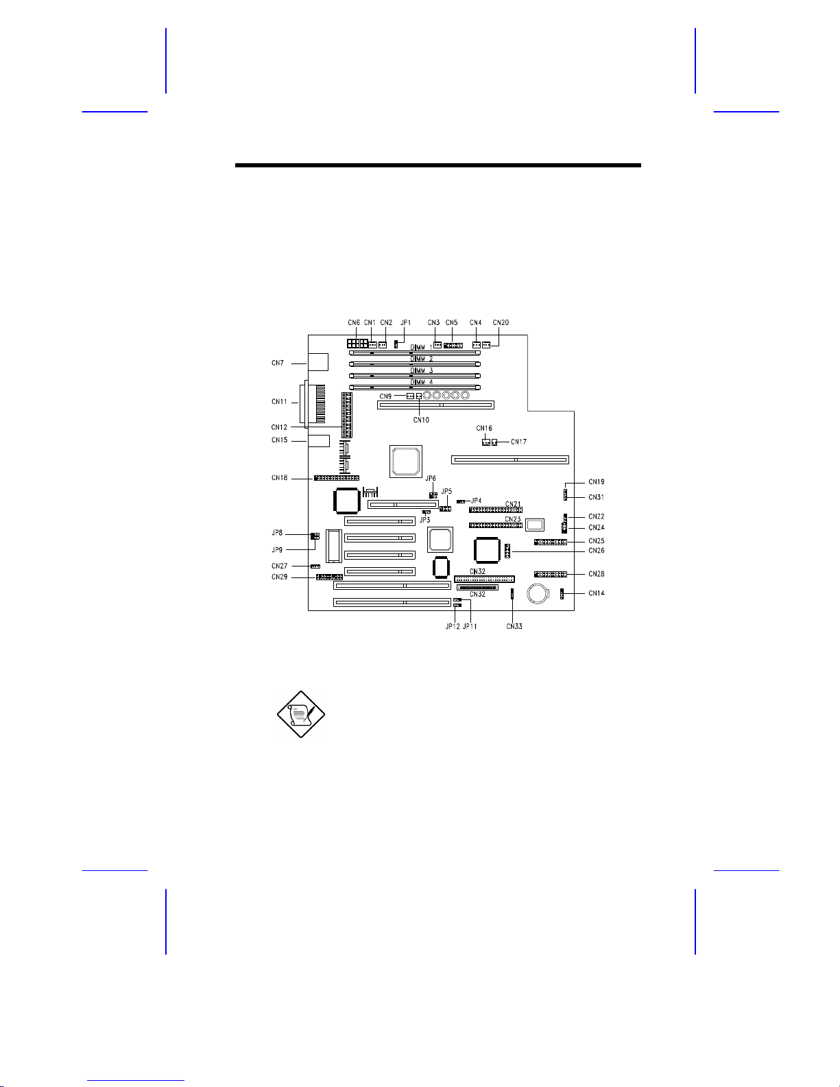
The system board utilizes both the ISA and the PCI local bus architecture.
Two ISA and four PCI bus slots (including one PCI/ISA shared slot) reside
on the board to allow installation of either master or slave devices.
Four memory banks composed of 168-pin dual inline memory module
(DIMM) sockets support a maximum system memory of 512 MB using
128-MB DIMMs. The sockets support both EDO and SDRAM-type
DIMMs.
A 50-pin Fast SCSI-II and a 68-pin Wide SCSI interface come with the
system board to connect SCSI devices. Standard I/O features such as two
enhanced IDE drive interfaces, two serial interfaces, one parallel port
interface, a diskette drive interface, and PS/2 mouse and keyboard
connectors reside on the system board.
The system board supports two optional features, the ASM Pro and the
remote diagnostic management (RDM), that allow better server