imtmedical CITREX H4 User manual

User Manual
CITREXH4

imtmedical ag
Gewerbestrasse 8
9470 Buchs (SG)
Switzerland
www.imtmedical.com

Table of Contents
1 Introduction 5
2 Intended use 6
3 Safety instructions 7
3.1 Representation of hazards, cautions and notes 7
3.2 Personnel 7
3.3 Responsibility and guarantee 7
3.4 Service life 7
4 Symbolexplanation 8
5 Start-up 9
5.1 Power supply 10
5.2 Mechanical connectors 11
5.3 Electrical interfaces 16
5.4 Replacing the CITREX battery 17
6 Operation 18
6.1 Switching the device on/off 18
6.2 Screen lock 18
6.3 Dim screen 18
6.4 User controls 19
6.5 Settings 20
6.6 Numerical readings 23
6.7 Graphical readings 24
6.8 Filter 24
7 Calibration 25
7.1 Zero point 25
7.2 Oxygen (O2) calibration 25
8 Connecting the device 27
8.1 Generalmeasurement setup 27
8.2 Measurement setup for checking ventilators 28
8.3 Measurement setup for gases at high pressure 28
9 Profile editor 29
9.1 Creating a profile 29
10 Configuration tool 31
10.1 PC minimum requirements 31
10.2 Web server 31
10.3 Monitoring option 32
11 Readingmeasurement data 34
11.1 Saving measurement data on the microSD card 34
11.2 Reading the data 34
12 Servicing and care 35
12.1 Preventivecleaning andservicing operations 35

13 Accessories andspare parts 36
13.1 Accessories table 36
14 Disposal 37
15 Directives andapprovals 38
16 Specifications 39
16.1 Measurement parameters 39
16.2 Interface definition 41
16.3 Gas type 42
16.4 Power supply 42
16.5 Battery operation 42
17 Appendix 43
17.1 Principle of flow measurement 43
17.2 Trigger 43
17.3 Measurement parameters and units 45
17.4 Gas standards for flow and volume readings 46
17.5 Conversion factors 47
17.6 List of tables 48
17.7 List of figures 48
17.8 Index 49

Introduction
5
imtmedical ag
1
CITREXH4 was developed in order to measure flow and various pressures and thus
calculate a large number of ventilation parameters. CITREXH4is a compact, mobile
and easy-to-operate measuring instrument. The integrated oxygen sensor makes
it possible for users to determine the oxygen concentration. The instrument is con-
trolled using 4 buttons on the front of the device and it has a large number of different
interfaces for data analysis.
The descriptions and instructions in this manual refer to the product CITREX H4.
In this User Manual the unit "sL/min" is based on ambient conditions of 0 °C and
1013.25mbar in accordance with DIN 1343.
This documentation applies to the followingversions:
CITREXH4 software: 4.1.000
CITREXH4 hardware: 4.0
In the case of older or newer versions there may be discrepancies in relation to this
User Manual.
Subject to technical modifications without notice.
Toavoid possible injuries,please read all the safety instructions be-
fore you use the product.
Thedevice is notintended for useoutside a building.
1 Introduction

Intended use
6
imtmedical ag
2
2
This product is intended for testing and calibration purposes on medical devices
orsystems thatgenerate gas flows or gas pressures. That includes ventilators and
anaesthetic equipment. The user of the device has received training on how to use
medical equipment and can perform repairs, maintenance and servicing on medical
devices. The device can be used in hospitals, in clinics, at device manufacturers or
at independent service companies that perform repairs or servicing operations on
medical devices.
CITREXH4is intended for use in a laboratory environment. It may only be used out-
side the nursing sector. It must not be used directly on patients or devices that are
connected to patients. The measuring instrument CITREXH4is intended for over-
the-counter sale.
With CITREXH4 you have the solution for measurements in the following areas:
• Flow
• Volume
• Differential pressure
• High pressure
• Ambient pressure
• Oxygen
• Temperature
In addition, various ventilation parameters can be measured:
• Ventilation rate
• Time
• Ratio
• Ti/ Tcyc
• Tidal volume
• Minute volume
• Peak flow
• Pressure
• Compliance
• Trigger
CITREXH4 is a measuring instrument for checking and calibrating
ventilators and anaesthetic equipment. It must not be used for patient
monitoring. During patient treatment by the ventilator it is not allowed
to connect to CITREXH4.
It is not allowed to measure liquids with CITREXH4.
2 Intended use

7
imtmedical ag
Safety instructions
3
Please read all the safety instructions carefully beforeyou use CITREXH4.
This User Manual uses the representation below to specifically draw attention to
residual risksduring intended use andemphasise important technical requirements.
Information and/or instructions andprohibitions to preventdamage of any kind,as
well as useful tips and information for handling the device, will be indicated by the
following icon:
Work on and with CITREXH4 may only be performed by persons
whohave undergone appropriate technical training andhave the
necessary experience.
The manufacturer accepts no responsibility or guarantee and will exempt itself from
liability claims accordingly if the operator or any third parties:
• Fail to use the device in accordance with its intended use.
• Disregard the specifications.
• Tamper with the device in any way (conversions, modifications or the like).
• Operate the device with accessories that are not listed in theassociatedsets
of product documentation.
Although the device meets high quality and safety standards andit
has been constructed and tested according to the current state of
the art, it is not possible to rule out the risk of injuries with serious
consequencesif the device is used in non-compliance with the in-
tended use (improperly) or is misused.
Therefore please read through this User Manual carefully and keep
this documentation in a readily accessible place close to your device.
The maximum service life of the device has been specified as 10 (ten) years, provided
it is handled properly in accordance with this User Manual.
3 Safety instructions
3.1 Representation of haz-
ards, cautions and notes
3.2 Personnel
3.3 Responsibility and
guarantee
3.4 Service life

Symbol explanation
8
imtmedical ag
4
Thesymbols listed belowmayappear on the packaging material,on the device rating
plate and in the User Manual of the CITREXH4 measuring instrument.
RS-232 interface
USB interface
SN BBXXXX Serial number
Analog interface
CAN CAN interface
Ethernet interface
On/Off button
SD card
Fragile contents
Keep dry
Read the User Manual
The device must not be disposed of in household waste
The device is CE approved
Caution: observe the safety instructions in the User Manual
Reusable packaging
Manufacturer's specification and date of manufacture
Keep away from heat
Temperature range for storage and transport
CSA monogram with C/US indicator
California Energy Commission Compliant
Table 1: Symbol explanation
4 Symbolexplanation

9
imtmedical ag
Start-up
5
CITREXH4
Power supply plug with country-specific adapters
USB cable
MicroSD card
Dust filter RT019
Laminar inlet pipe
CITREX carrying case
Network cable
Car adapter
Adapter set
Table 2: Scope of delivery
5 Start-up
Start-up
10
imtmedical ag
5
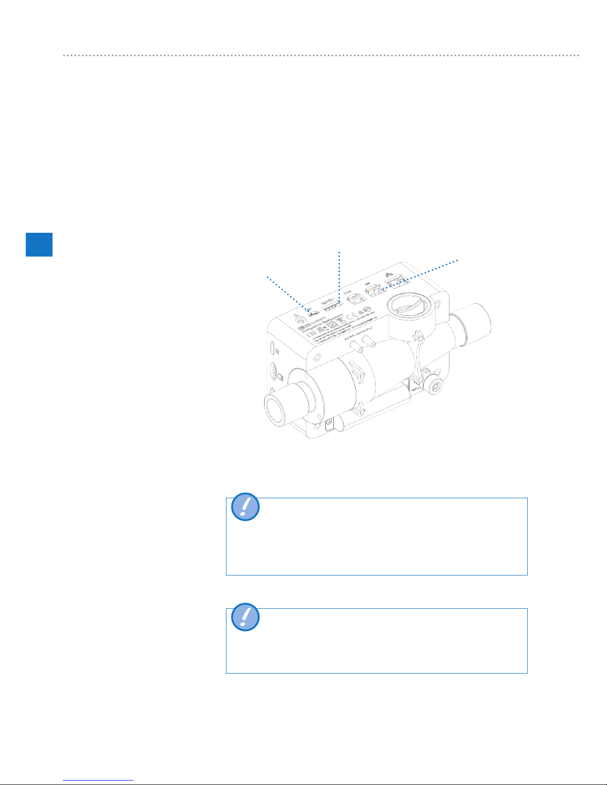
CITREXH4can be operatedfrom the mains or from theintegrated battery.
Power can be supplied via the USB port (Mini B), the analog interface or the CAN
interface on the top of CITREXH4. Use the power supply unit included to charge the
battery or operate the device via the USB port. You will find more information about
power supply and how to configure the plugs in the section "Electrical interfaces".
During the charging process a green battery symbol is lit on the front.
Please connect the power supply unit included to a voltage of 100VAC to 240VAC
with a frequency of 50Hz to 60Hz.
USB port
Analog interface
CAN interface
Figure 1: Power supply
Before switching on, make sure theoperating voltage ofthe power
supply unitagrees with thelocalmains voltage. You will find this
information on the rating plate on the back of the power supply unit.
When operating CITREXH4via the USB port only use the original
power supply unit included!
Thedevice indicates visually and audiblywhen the battery has to be
charged. Please do not store the battery in a depleted state.
Caution: depletion can damage the battery beyond repair!
5.1 Power supply

Start-up
11
imtmedical ag
5
5.2.1 Flow channel
The flow channel can be used bidirectionally. The positive flow direction is from left
to right, viewed from the front of the device. The measurements of volume, flow, gas
temperature, oxygen and channel pressure are taken in the flow channel. The values,
and the ventilation parameters calculated from them, can be displayed on the screen.
You will find the relevant setting options in the section "Operation".
Flow (air) Measuring range ± 300 sL/min
Accuracy ± 1.9 % of reading or ± 0.1 sL/min
Volume Measuring range 0 – 10 sL
Accuracy ± 2 % of reading or ± 0.02 sL
Temperature Measuring range 0 – 50 °C
Accuracy ± 1.75% of reading or 0.5 °C
Oxygen Measuring range 0 – 100 %
Accuracy ± 1 % O2
Pressure in flow
channel
Measuring range −50 – +150 mbar
Accuracy ± 0.75 % of reading or ± 0.1 mbar
Flow channel
Figure 2: Flow channel
5.2 Mechanical connectors

Start-up
12
imtmedical ag
5
5.2.2 Differential pressure
This pressure connector measures the difference in pressure between the two con-
nectors. If only one connector is used for a measurement, pressure measurement
takes place at ambient pressure. The measuring range is −200 mbar to +200 mbar.
Please comply with the maximum permissible pressure at the connector. The sensor
values from this pressure sensor can be displayed in the menu with the parameter
"PDiff".
Differential pressure connector
Figure 3: Differential pressure connector
Measuring range ± 200 mbar
Accuracy ± 0.75 % of reading or ± 0.1 mbar
Pressures above 1 bar damage the differential pressure sensor be-
yond repair!

Start-up
13
imtmedical ag
5
5.2.3 High pressure
The high-pressure connector measures the applied pressure up to 10 bar. It is rec-
ommended that the differential pressure connector be used for measurements up to
200 mbar. It is up to 100 times more accurate. The sensor values measured can be
displayed with the parameter "PHigh".
The high-pressure connector can be fitted with a DISS adapter for air and oxygen.
You will find the ordering code in the section "Accessories and spare parts".
High-pressure connector
Figure 4: High-pressure connector
Measuring range 0 – 10 bar
Accuracy ± 1 % of reading or 10 mbar
Pressures above 15 bar damage the high-pressure sensor beyond
repair!
Do not use a tool to tighten the adapter on the high-pressure port
since this can damage the plastic casing. Please only tighten manu-
ally.

Start-up
14
imtmedical ag
5
5.2.4 Oxygen sensor
CITREXH4 can measure the oxygen concentration in the flow channel. To do so, an
oxygen sensor is screwed into the appropriate port. The oxygen sensor has to be
connected to the measuring instrument using the cable included. The following steps
explain how to install and replace the oxygen sensor.
Oxygen sensor holder
Figure 5: Oxygen sensor holder
Measuring range 0 – 100 %
Accuracy ± 1 % O2(absolute)
5.2.5 Installing the oxygen sensor
1. Remove the protective cap from the sensor port of the device.
Figure 6: Protective cap

Start-up
15
imtmedical ag
5
2. Screw the oxygen sensor clockwise into the appropriate port. Make sure the sen-
sor seals off the port and there is no leak.
Figure 7: Screwing in the oxygen sensor
3. Connect the cable included to the oxygen sensor by pushing the cable into the
hole at the top of the sensor until the cable locks into place. Connect the other end
of the cable to CITREXH4 by inserting it into the hole provided, which is labelled
"O2".
Figure 8: Oxygen sensor cable
4. Perform an oxygen calibration. The calibration procedure is described in the sec-
tion "Calibration". Calibration ensures that the measured values of the new sensor
are correct.

Operation
16
imtmedical ag
6
Figure 9 shows the available electrical interfaces of CITREXH4.
1
2
3
4
5
6
7
Figure 9: Electrical interfaces
1MicroSD
card slot
The firmware of CITREXH4is stored on the microSD
card. It also contains customised configurations and test
reports can be saved on the memory card. You will find
more information in the section "Reading measurement
data".
2O2interface The oxygen sensor is connected to CITREXH4via the
O2interface. You will find further information on this in the
section "Oxygen sensor".
3USB port The USB port is used to operate the device from the
mains power supply and to charge the device battery but
it can also be used as a data interface. It is a "USB Mini-B
port".
4Analog OUT The Analog Out port is used for reading analog signals. It
is also possible to connect an external trigger. Two ports
are reserved for mains operation and charging the device
battery. You will find the ordering code for the matching
connector in the section "Accessories and spare parts".
You will find additional technical information about the port
in the section "Interface definition".
5RS-232 The RS-232 port is used as a data interface. In the sec-
tion "Interface definition" you will find further information
about the interface.
6CAN The CAN interface is prepared in the device but at present
it is not yet supported by the firmware. The CAN interface
can be used for charging the device battery. You will
find information about the port in the section "Interface
definition".
7Ethernet The Ethernet interface is used to configure the device and
it is used as a data interface. You will find more informa-
tion in the section "Reading measurement data".
Table 3: Description of electrical interfaces
5.3 Electrical interfaces

Operation
17
imtmedical ag
6
The battery of CITREX H4 can be replaced by the user. To do so, undo the two
screws on the back of the device and remove them. Then the battery can be re-
moved and replaced. Check to make sure the new battery is inserted properly. For
this purpose the terminals must be above one another.
Figure 10: Replacing the battery
5.4 Replacing the CITREX battery

Operation
18
imtmedical ag
6
This section describeshow to use the device and whatpossible uses there are.
The device is switched on and off at the On/Off button. Figure 11, section "User
controls",shows where this button is located on the device. To switch CITREXH4on
you must press the On/Off button briefly. You will hear an audible signal. To switch
the device off you must press the On/Off button for about 1second. If the device can
no longer be controlled, you have the option of pressing the On/Off button for about
6seconds. The device is then forced to shut down.
Press the context button on the side of the device for 2 seconds. The screen shows
a message indicating that the screen is locked. To unlock the screen, press and hold
down the context button or one of the four buttons on the front for 2 seconds.
If the device is not operated by the user, the display of CITREXH4 shuts down after
about one minute and the four buttons start to flash. As soon as a button is pressed,
the screen comes on again.
The setting for how long it takes until the display is dimmed can be customised using
the configuration tool. You will find further information on this in the section "Config-
uration tool".
6 Operation
6.1 Switching the device on/off
6.2 Screen lock
6.3 Dim screen

Operation
19
imtmedical ag
6
1
2
3
456
8
9
10
7
Figure 11: User controls
1 Change, Edit
2 Context button; long press: key lock on/off
3 On/Off button
4 Menu button; zero point adjustment
5 Charge indicator
6 Flow direction indicator
7 Screen
8 Measurement values
9 Malfunction indicator
10 Measurement curves
Table 4: User controls
6.4 User controls

Operation
20
imtmedical ag
6
With the × button you return to the Settings menu. By pressing the button more than
once you can view the various settings of the measuring instrument.
6.5.1 Info display
This display provides information about the owner, the company, the next recom-
mended calibration, the software version and the hardware revision. Settings con-
cerning the owner can be edited with the configuration tool.
Figure 12: Info display
6.5.2 Battery indicator
The battery indicator informs you about the level of the battery charge.
Figure 13: Battery indicator
6.5.3 Ethernet interface
Here it is possible to make various settings for the network connection. With the
button you can choose between the options "DHCP Client", "Default" and "Config-
ured". The setting does not have to be confirmed and it is enabled as soon as it is
visible on the screen. More information about the settings is available in the section
"Web server".
Figure 14: Ethernet interface
6.5 Settings
Table of contents


