Incite Fire SEC-HIM-35 User manual

Incite Hochiki-Securiton Interface Module– Rev 1.0 Page 1 of 21

Incite Hochiki-Securiton Interface Module– Rev 1.0 Page 2 of 21
Index
1General....................................................................................................................................................3
2Modules ..................................................................................................................................................3
2.1 SEC-HIM-35 ........................................................................................................................................... 3
2.2 SEC-HIM-35B ...........................................................................................Error! Bookmark not defined.
2.3 SYNCRO-SECRDU and TAKTIS-SECRDU .................................................................................................. 4
3Operation:...............................................................................................................................................5
3.1 Alarm:.................................................................................................................................................... 5
3.2 Fault Mode: ........................................................................................................................................... 5
3.3 Controls: ................................................................................................................................................ 5
3.3.1 Reset: ................................................................................................................................................ 5
3.3.2 Disable: ............................................................................................................................................. 5
4Configuration: .........................................................................................................................................6
4.1 SEC-HIM-35 and SEC-HIM-35B .............................................................................................................. 6
4.2 SYNCRO-SECRDU and TAKTIS-SECRDU .................................................................................................. 6
4.2.1 Unit addresses .................................................................................................................................. 6
4.2.2 Config Switch: ................................................................................................................................... 6
5FIP Configuration.....................................................................................................................................7
5.1 General.................................................................................................................................................. 7
5.2 SEC-HIM-35 ........................................................................................................................................... 8
5.3 SEC-HIM-35B ....................................................................................................................................... 10
5.4 SYNCRO-SECRDU ................................................................................................................................. 11
5.4.1 I/O Setup and Attributes................................................................................................................. 11
5.4.2 Syncro Cause and Effect Programming........................................................................................... 13
5.5 TAKTIS-SECRDU .......................................................................................Error! Bookmark not defined.
5.5.1 I/O Setup and Attributes................................................................................................................. 14
5.5.2 Taktis Cause and Effect Programming ............................................................................................ 16
6Installation ............................................................................................................................................17
6.1 SEC-HIM-35, SEC-HIM-35B .................................................................................................................. 17
6.2 SYNCRO-SECRDU and TAKTIS-SECRDU ................................................................................................ 19
6.2.1 Syncro Installation .......................................................................................................................... 19
6.2.2 Taktis Installation............................................................................................................................ 19
6.2.3 Cabling ............................................................................................................................................ 20

Incite Hochiki-Securiton Interface Module– Rev 1.0 Page 3 of 21
1General
The Incite Hochiki-Securiton Interface Module (SEC-HIM-35) has been designed to enable Securiton
Aspirating Smoke Detectors to be connected to a Hochiki loop and bring the alarm and fault signals
back to the panel for processing.
There are three parts to a complete system.
SEC-HIM-35: This is the main module which utilises a CHQ-POM to interfaces the Aspirating
Smoke Detector (ASD) to the loop. Every system must contain one of these.
SEC-HIM-35B: This is a secondary module which in only required on an ASD535/2. It utilises a CHQ-
SIM to interface the second ASD to the loop. It contains a cable to connect to the SEC-HIM-35 unit.
SYNCRO-SECRDU and TAKTIS-SECRDU: These modules are used to display the status of the
ASDs, and allow individual Disable and Reset switches for each ASD.
2Modules
2.1 SEC-HIM-35
The Hochiki-Securiton Interface Module consists of two parts connected via a ribbon cable.
These are available only as a complete set.
The control PCB consists of a CHQ-POM, and associated electronics
to allow it to interface to the Securiton ASD-531, ASD-532 and
ASD535 detectors.
The termination PCB consists of fingers to fit into the terminal
blocks on the Securiton detectors. Two box headers are provided
to allow the ribbon from the control PCB to plug in. Header J1 is
used for the ASD531 and ASD532 detector, while header J2 is used
for the ASD535 detector.
2.2 SEC-HIM-35B
This module is only used with the Securiton ASD535 when the
second aspirator is installed and plugs into the SEC-HIM-35. It
can only be used in conjunction with the SEC-HIM-35. The SEC-
HIM-35B utilises a CHQ-SIM.
Incite Hochiki-Securiton Interface Module– Rev 1.0 Page 4 of 21
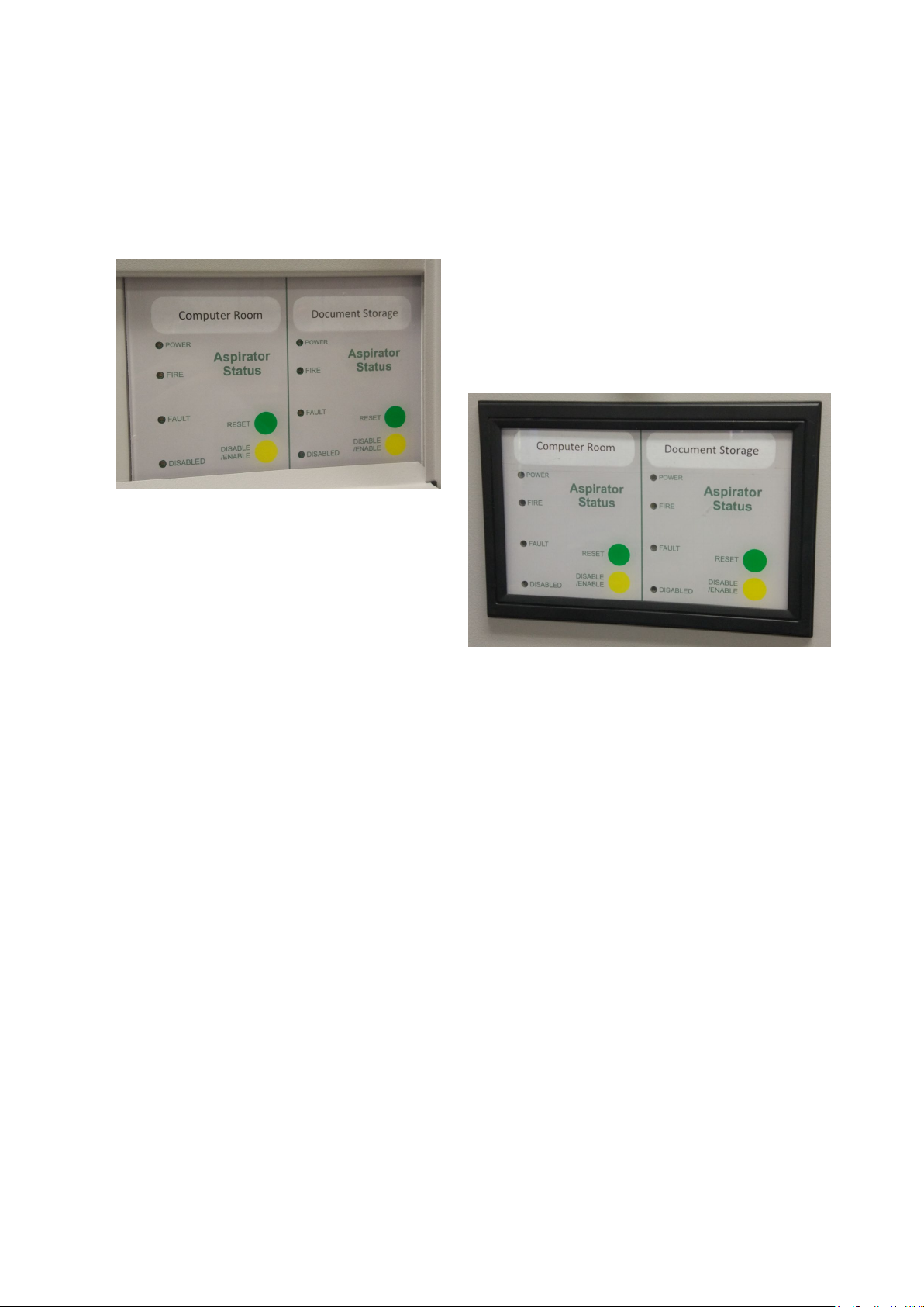
2.3 SYNCRO-SECRDU and TAKTIS-SECRDU
These modules are used to display the status of individual Securiton ASD units. They must be
configured through Cause and Effects in the Syncro or Taktis panels. They must be used in
conjunction with either a Syncro or Taktis panel and are not available in a stand-alone configuration.
These modules come only as pairs. Should only one be needed, the second unit is left out of the FIP
configuration.

Incite Hochiki-Securiton Interface Module– Rev 1.0 Page 5 of 21
3Operation:
The state of the ASD outputs are detected by the main interface module (SEC-HIM-35) and
transmitted back to the FIP via the CHQ-POM and the Hochiki Loop. These are then available for
processing via the FIP. The ASD reset is achieved by toggling the CHQ-POM output for 5 seconds,
which in turn is fed into the ASD Reset input.
On the SECRDU, the LEDs are controlled, and the Disable and Reset touch buttons are processed via
Cause and Effect equations in the Syncro or Taktis FIP.
3.1 Alarm:
When the first alarm contact closes on the ASD, the resistor network on the SEC-HIM-35 sets an
alarm on the CHQ-POM input 1. This is then detected by the FIP and processed as per the settings in
the FIP configuration.
Similarly, when a second detector head is used in the ASD535, the second alarm contact sets an
alarm on the CHQ-SIM located on the SEC-HIM-35B module.
3.2 Fault Mode:
All the inputs on the SEC-HIM-35 and SEC-HIM-35B are monitored for open circuit and short circuit
faults. Should any portion of the unit be unplugged, a fault will be generated.
When the fault contact on the ASD is activated, the second input on the CHQ-POM is activated. This
allows the input to signal a fault and also trigger other devices through C&E if needed.
3.3 Controls:
The control buttons on the SECRDU are capsense type. They are activated by placing a finger onto
the faceplate, where the finger capacitance is detected by the PCB circuitry. A buzzer will beep
whenever a finger is detected.
3.3.1 Reset:
This button has a momentary function. Activating this button will place a 5 second reset pulse n the
connected ASD unit. If the alarm is still present on the ASD, it will have no effect.
3.3.2 Disable:
This button has a toggle operation. Activating this button will disable the Alarm and Fault inputs
from the ASD. If required, the FIP C&E can be used to turn off the ASD when this button is activated
by holding the reset signal on the ASD.

Incite Hochiki-Securiton Interface Module– Rev 1.0 Page 6 of 21
4Configuration:
4.1 SEC-HIM-35 and SEC-HIM-35B
These are configured through the FIP. See Section 5 (FIP Configuration)
4.2 SYNCRO-SECRDU and TAKTIS-SECRDU
4.2.1 Unit addresses
This is addressed in binary, with each switch representing a number as follows
Switch
Value
SW2.1
1
SW2.2
2
SW2.3
4
SW2.4
8
SW2.5
16
SW2.6
Not used
SW2.7
Not used
SW2.8
RS485
Termination
For example: to specify address 14, switches 2, 3, and 4 would be turned on (2+4+8 = 14)
The RS485 termination should only be turned on if the unit is the last one on the communications
bus.
4.2.2 Config Switch:
The control buttons on the SECRDU are capsense type. They are activated by placing a finger onto
the faceplate, where the finger capacitance is detected by the PCB circuitry. The sensitivity can be
fine-tuned by switches 1 to 4 on the configuration switch SW3. It should not be necessary to move
the switches from their default setting. Settings are only read on a board reset. To perform a reset,
momentarily press SW1, which is located between the DIP switches.
The switch setting are as below:
SW3.4
SW3.3
SW3.2
SW3.1
Finger Capacitance
OFF
OFF
OFF
OFF
0.1pF
OFF
OFF
OFF
ON
0.1pF
OFF
OFF
ON
OFF
0.2pF
Taktis Default
OFF
OFF
ON
ON
0.3pF
OFF
ON
OFF
OFF
0.4pF
OFF
ON
OFF
ON
0.5pF
OFF
ON
ON
OFF
0.6pF
Syncro Default
OFF
ON
ON
ON
0.7pF
ON
OFF
OFF
OFF
0.8pF
ON
OFF
OFF
ON
0.9pF
ON
OFF
ON
OFF
1pF
ON
OFF
ON
ON
1pF
ON
ON
OFF
OFF
1pF
ON
ON
OFF
ON
1pF
ON
ON
ON
OFF
1pF
ON
ON
ON
ON
1pF

Incite Hochiki-Securiton Interface Module– Rev 1.0 Page 7 of 21
The Taktis is by default more sensitive to take into account the thicker faceplate material.
Increasing the finger capacitance makes the ‘button’ LESS sensitive.
Decreasing the finger capacitance makes the ‘button’ MORE sensitive.
Care must be taken not to make the button too sensitive, or false triggering may occur, similarly, if
the sensitivity is reduced too far, the button will not work at all.
5FIP Configuration
5.1 General
The SEC-HIM-35 is presented to the FIP as a CHQ-POM device, while the SEC-HIM-35B is presented
to the FIP as a CHQ-SIM.Both the SYNCRO-SECRDU and the TAKTIS-SECRDU are presented to the FIP
as a 16 I/O Card.

Incite Hochiki-Securiton Interface Module– Rev 1.0 Page 8 of 21
5.2 SEC-HIM-35
The SEC-HIM-35 should be configured as:
CHQ-POM Output
CHQ-POM Input 1

Incite Hochiki-Securiton Interface Module– Rev 1.0 Page 9 of 21
CHQ-POM Input 2
Note: When Input 1 is set to Latching, a 10 second
delay must be placed on the input in order for it to
reset with a Panel Reset. Failure to do so, will result in
the point re-alarming and a second reset needing to be
performed.

Incite Hochiki-Securiton Interface Module– Rev 1.0 Page 10 of 21
5.3 SEC-HIM-35B
The SEC-HIM-35B should be configured as:
Note: When the Input is set to Latching, a
10 second delay must be placed on the
input in order for it to reset with a Panel
Reset. Failure to do so, will result in the
point re-
alarming and a second reset
needing to be performed.

Incite Hochiki-Securiton Interface Module– Rev 1.0 Page 11 of 21
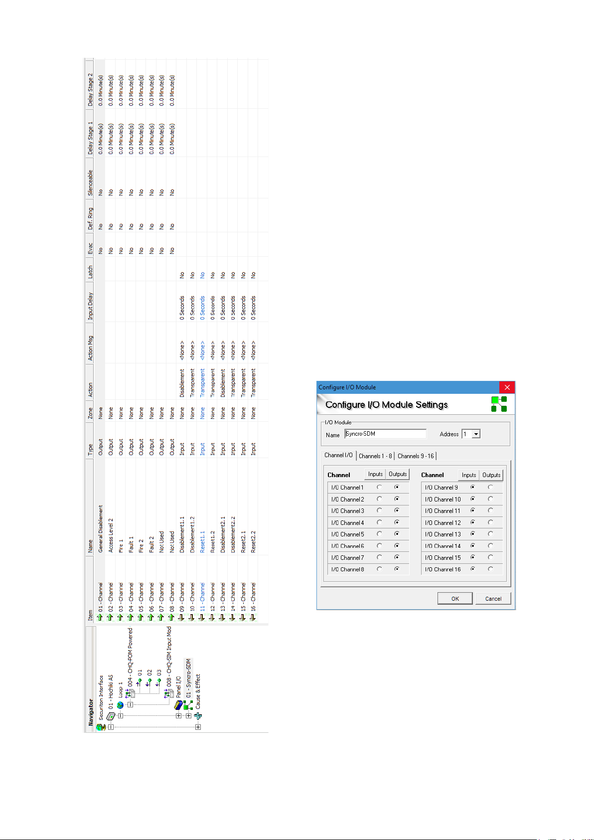
5.4 SYNCRO-SECRDU
5.4.1 I/O Setup and Attributes
The SYNCRO-SECRDU appears to the Syncro panel as a 16 way I/O module.
The I/O points are shown in the table below:
I/O
Channel
Function
Syncro Input
or Output
Description
1
General Disablement
Output
NOT USED
2
Access Level 2
Output
Enables SECRDU controls.
3
Fire 1
Output
Fire signal from ASD1
4
Fault 1
Output
Fault signal from ASD1
5
Fire 2
Output
Fire signal from ASD2
6
Fault 2
Output
Fault signal from ASD2
7
Not Used
Output
DO NOT USE
8
Not Used
Output
DO NOT USE
9
Disablement 1.1
Input
Activated whenever the Disablement
function on ASD1 is active. Used to disable
inputs via C&E.
10
Disablement 1.2
Input
May be used as required. Is activated
whenever
the Disablement function on
ASD1 is active.
11
Reset 1.1
Input
Activated for 5 seconds whenever the Reset
function on ASD1 is activated. Used to reset
the ASD via C&E.
12
Reset 1.2
Input
May be used as required. Is Activated for 5
seconds whenever the Reset function on
ASD1 is activated.
13
Disablement 2.1
Input
Activated whenever the Disablement
function on ASD2 is active. Used to disable
inputs via C&E.
14
Disablement 2.2
Input
May be used as required. Is activated
whenever the Disablement function on
ASD2 is active.
15
Reset 2.1
Input
Activated for 5 seconds whenever the Reset
function on ASD2 is activated. Used to reset
the ASD via C&E.
16
Reset 2.2
Input
May be used as required. Is Activated for 5
seconds whenever the Reset function on
ASD2 is activated.
Incite Hochiki-Securiton Interface Module– Rev 1.0 Page 12 of 21
I/O points and channel attributes
should be set as shown:
All outputs should have attributes
CLEARED.
Input 9, and 13 should be set to
DISABLEMENT, all other inputs
should be set to TRANSPARENT,
NON-LATCHING.

Incite Hochiki-Securiton Interface Module– Rev 1.0 Page 13 of 21
5.4.2 Syncro Cause and Effect Programming
Note: In this example an ASD535 with dual sampling tubes are used
Function
Type
Cause
Operator
Effect
Comment
Fault 1 and 2
Action
CHQ-POM Input
2
OR
SECRDU Channels
4 and 6
The ASD 535-2 has
only one fault
output for both
sensors.
Fire 1
Action
CHQ-POM Input
1
OR
SECRDU Channel 3
Fire 2
Action
CHQ-SIM Input
OR
SECRDU Channel 5
ASD535.1
Reset
Action
SECRDU
Channel 11
OR
CHQ-POM Output
ASD535.2
Reset
Action
SECRDU
Channel 15
OR
CHQ-POM Output
The ASD 535-2 has
only one reset
input output for
both sensors.
ASD535.1
Disablement
Disablement
SECRDU
Channel 9
OR
CHQ-POM Input 1
ASD535.2
Disablement
Disablement
SECRDU
Channel 13
OR
CHQ-SIM Input
ASD535.1 and
2 Disablement
Disablement
SECRDU
Channel 9 and
13
AND
CHQ-POM Input 2
We have a common
fault, so only
disable it when
both are disabled
ASD535.1 and
2 Total
Disablement
Action
SECRDU
Channel 10 and
14
AND
CHQ-POM Output
This used the aux
disablement
outputs to turn off
the ASD.

Incite Hochiki-Securiton Interface Module– Rev 1.0 Page 14 of 21
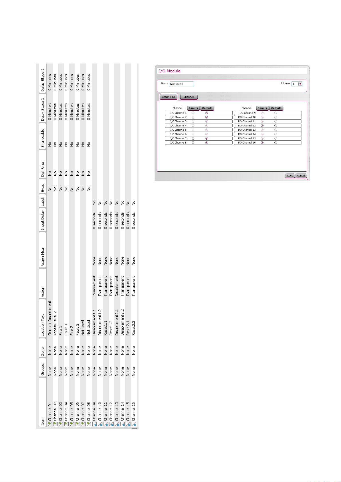
5.5 TAKTIS-SECRDU
5.5.1 I/O Setup and Attributes
The TAKTIS-SECRDU appears to the Taktis panel as a 16 way I/O module. When adding the module,
the wired type must be used, not the “Plug in” type.
The I/O points are shown in the table below:
I/O
Channel
Function
Syncro Input
or Output
Description
1
General Disablement
Output
NOT USED
2
Access Level 2
Output
Enables SECRDU controls.
3
Fire 1
Output
Fire signal from ASD1
4
Fault 1
Output
Fault signal from ASD1
5
Fire 2
Output
Fire signal from ASD2
6
Fault 2
Output
Fault signal from ASD2
7
Not Used
Output
DO NOT USE
8
Not Used
Output
DO NOT USE
9
Disablement 1.1
Input
Activated whenever the Disablement
function on ASD1 is active. Used to disable
inputs via C&E.
10
Disablement 1.2
Input
May be used as required. Is activated
whenever the Disablement function on
ASD1 is active.
11
Reset 1.1
Input
Activated for 5 seconds whenever the Reset
function on ASD1 is activated. Used to reset
the ASD via C&E.
12
Reset 1.2
Input
May be used as required. Is Activated for 5
seconds whenever the Reset function on
ASD1 is activated.
13
Disablement 2.1
Input
Activated whenever the Disablement
function on ASD2 is active. Used to disable
inputs via C&E.
14
Disablement 2.2
Input
May be used as required. Is activated
whenever the Disablement function on
ASD2 is active.
15
Reset 2.1
Input
Activated for 5 seconds whenever the Reset
function on ASD2 is activated. Used to reset
the ASD via C&E.
16
Reset 2.2
Input
May be used as required. Is Activated for 5
seconds whenever the Reset function on
ASD2 is activated.
Incite Hochiki-Securiton Interface Module– Rev 1.0 Page 15 of 21
I/O points should be set as follows
Channel attributes should be set as shown:
All outputs should have attributes CLEARED.
Input 9, and 13 should be set to DISABLEMENT, all
other inputs should be set to TRANSPARENT,
NON-LATCHING.

Incite Hochiki-Securiton Interface Module– Rev 1.0 Page 16 of 21
5.5.2 Taktis Cause and Effect Programming
Note: In this example an ASD535 with dual sampling tubes are used
Function
Type
Cause
Operator
Effect
Comment
Fault 1 and 2
Action
CHQ-POM Input
2
OR
SECRDU Channels
4 and 6
The ASD 535-2 has
only one fault
output for both
sensors.
Fire 1
Action
CHQ-POM Input
1
OR
SECRDU Channel 3
Fire 2
Action
CHQ-SIM Input
OR
SECRDU Channel 5
ASD535.1
Reset
Action
SECRDU
Channel 11
OR
CHQ-POM Output
ASD535.2
Reset
Action
SECRDU
Channel 15
OR
CHQ-POM Output
The ASD 535-2 has
only one reset
input output for
both sensors.
ASD535.1
Disablement
Disablement
SECRDU
Channel 9
OR
CHQ-POM Input 1
ASD535.2
Disablement
Disablement
SECRDU
Channel 13
OR
CHQ-SIM Input
ASD535.1 and
2 Disablement
Disablement
SECRDU
Channel 9 and
13
AND
CHQ-POM Input 2
We have a common
fault, so only
disable it when
both are disabled
ASD535.1 and
2 Total
Disablement
Action
SECRDU
Channel 10 and
14
AND
CHQ-POM Output
This used the aux
disablement
outputs to turn off
the ASD.

Incite Hochiki-Securiton Interface Module– Rev 1.0 Page 17 of 21
6Installation
6.1 SEC-HIM-35, SEC-HIM-35B
Locate and install the mounting bracket in the first slot and fasten
with the Torx screw provided with the bracket.
Locate the relevant plug for the type of ASD and
connect the SEC-HIM-35.
On the ASD531 and ASD532, install the board in
terminals 8 to 16. Note the 2 fingers not
connected.
On the ASD535, install the board in terminals 10
to 20.
Incite Hochiki-Securiton Interface Module– Rev 1.0 Page 18 of 21
Install the loop wiring into the CHQ-POM
on the SEC-HIM-35, then slide the unit into
the carrier, making sure that no cables are
pinched.
To install the SEC-HIM-35B, first install mounting
bracket in the second slot and fasten with the Torx
screw provided with the bracket.
Install the loop wiring into the CHQ-SIM on the SEC-
HIM-35, then slide the unit into the carrier, making sure
that no cables are pinched.
Route the interconnection cable in a position where it
can’t get damaged and plug it into the receptacle
provided on the SEC-HIM-35.

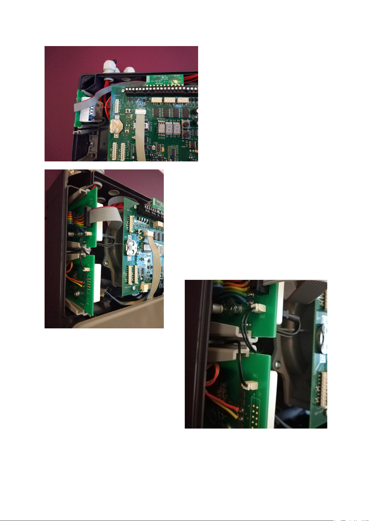
Incite Hochiki-Securiton Interface Module– Rev 1.0 Page 19 of 21
6.2 SYNCRO-SECRDU and TAKTIS-SECRDU
The SECRDU units are supplied as complete units with integrated faceplates.
These units should not be dismantled, and will be irreparably damaged if dismantling is attempted.
6.2.1 Syncro Installation
Using the template provided, modify, print
off, cut out the label and slide it into the
label pocked on the side of the SECRDU
module.
Place the SYNCRO-SECRDU behind the
carrier plate opening. Using the M3 screws
provided, attach the SECRDU to the carrier
plate.
6.2.2 Taktis Installation
Using the template provided, modify, print
off, cut out the label and slide it into the
label pocked on the side of the SECRDU
module.
Place the TAKTIS-SECRDU squarely in front of
the opening in the carrier plate opening, and
working from each side, carefully ease the
attachment clips through the opening.

Incite Hochiki-Securiton Interface Module– Rev 1.0 Page 20 of 21
6.2.3 Cabling
Four cables are required to interface the SECRDU to the FIP: 24V, 0V, Comms+, Comms-
Do not put 24V onto the Comms terminals or permanent damage may result, and warranty will be
void.
Insert the cabled into the top of its respective terminal while pushing GENTLY vertically downwards
on the white terminal release button.
Incoming and outgoing terminals are provided. The termination switch on the last unit must be
switched on, otherwise it must be switched off.
To remove the cables, GENTLY push in the white terminal release button for that cable.
This manual suits for next models
3
Table of contents


