Indol 200A++ User manual
Operation & Installation Manual
Operation & Installation Manual
Air source hot water heat pump
Air source hot water heat pump
COMPACT
COMPACT
INDOL
INDOL

Preface
The installer shouldexplain to theuser how tooperate and maintainthe unit accordingto
the manual, whenthe unit isinstalled. Andask the userto read themanual carefully, keep
the manual anddo the operationin strict accordancewith the Manual.
This manual includesall the necessaryinformation about installation,debugging,
discharging and maintenance. Please read thismanual carefully beforeyou open or
maintain the unit.
When install theunit and connectthe pipe, pleasecarry it outstrictly according tothe
manual.
Once finish theinstallation and connection,please make everythingok before poweron the
unit.
The manufacture ofthis product willnot be heldresponsible if someoneis injured orthe unit
is damaged, asa result ofimproper installation, debugging,unnecessary maintenance
which is notin line withthis manual.
It is vitalthat the belowinstructions are adheredto at alltimes to keepthe warranty.
---Maintenance and operation must be carriedout according tothe recommended timeand
frequency, as stated inthis manual.
---Failure to complywith these recommendationswill invalidate thewarranty.
The manual willbe changed ifthere is anyimprovement on theunit, there willnot be
advance notice.

1. Safety Precaution
2. Specs
2.1) Appearance
2.2) Characteristic
2.3) Principle
2.4) Dimensions
2.5) Performance Parameter
3. Function Presentation
4. Installation
4.1) Installation Sketch Map
4.2) Choose the Suitable Unit
4.3) Deposited and Transportation
4.4) Installation Position
4.5) Water Loop Connection
4.6) Wire Connection
4.7) Trial Running
5. Usage
5.1) Icons Introduction
5.2) Operation
5.3) Parameter
6. Maintenance and Repair
6.1) Maintenance
6.2) Trouble Shooting
7.Appendix
7.1) Appendix 1
Content
Content
1
3
3
3
4
5
6
7
8
8
8
9
9
10
12
12
13
13
15
26
27
27
28
28
28

1
1.Safety Precaution
1.The hurt means no need to be in hospital and cure for a long time, it's
injury, burn and get an electric shock.
2.The material lost means property and datum lost.
Concentration
limits
Toprevent the usersand others fromthe unpredictable/unexpected hurtof this unit,and
avoid damage onthe unit orother property, please usethe heat pumpproperly, please read
this manual carefullyand understand thefollowing information correctly.
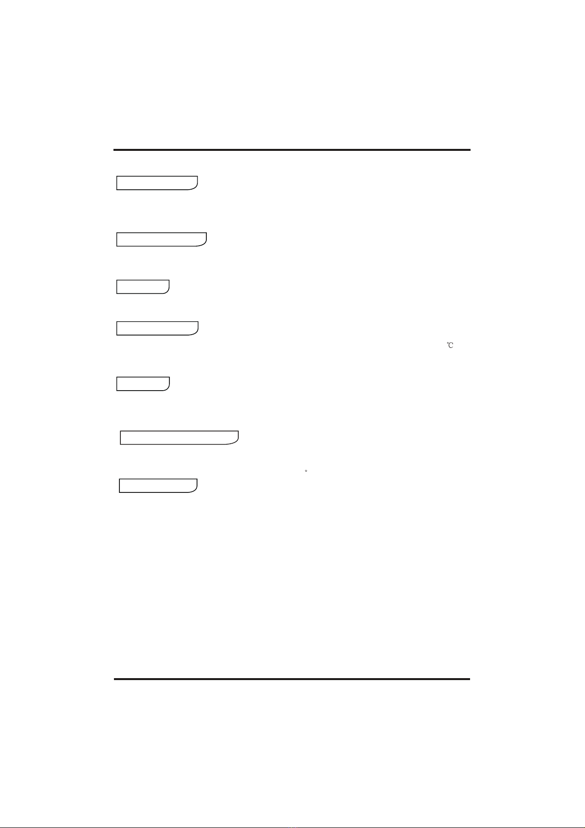
Safety Precaution
Installation warning
The heat pump must be installed by qualified personnel,
to avoid improper installation which can lead to water
leakage, electrical shock or fire.
Professional installer
is required
Earthing is required
Please make sure that the unit and power connection
have good earthing, otherwise may cause electrical
shock.
When install theunit in a small room, please take some
measures to prevent the asphyxia caused by the leakage
of refrigerant. Pleaseconsult the dealerfor concrete
measures.
Icon
Compulsory implement. The listed action need to be taken.
ATTENTION (include WARNING)
Please pay attention to what is indicated.
Prohibition. What is prohibited will be nearby this icon.
Mark Meaning
A wrongoperation may lead to death or heavy injury on people.
A wrongoperation may lead to hurt on people or loss of
material.
WARNING
ATTENTION
Meaning
2
Installation place
Fix the unit
Need circuit
breaker
The unit CANNOTbe installed nearthe flammable gas.Once there is
any leakage ofthe gas, firecan be occur.
Make sure thatthe basement ofthe heat pumpis strong enough,to
avoid any declineor fall downof the unit.
Make sure thatthere is circuitbreaker for theunit, lack ofcircuit breaker
can lead toelectrical shock orfire.
Prohibition
Entrust
Entrust
Check the install
placement
Prohibit
Shut off the power
Prohibit
Shut off the power
Do not putfingers or othersinto the fans.Children should besupervised
to ensure thatthey do notplay with theappliance.
When there issomething wrong orstrange smell, thepower supply need
to be shutoff to stop the unit.
Operation warning
Move and repair
Prohibition
When the heatpump need tobe moved orinstalled again, please
entrust dealer orqualified person tocarry it out.Improper installation
will lead towater leakage, electricalshock, injury orfire.
It is prohibitedto repair theunit by theuser himself, otherwiseelectrical
shock or firemay be occur.
When the heatpump need tobe repaired, pleaseentrust dealer or
qualified person tocarry it out.Improper movement orrepair on theunit
will lead towater leakage, electricalshock, injury orfire.
Operation attention
The unit mustbe installed indoor, and the ambient temperature must be
over 0¡æ,if do notuse the unitfor a longtime and theenvironment
temperature is below0¡æ, please drainthe water inthe tank toprevent
When do theclean, must stopthe unit andshut off the power, if do not
stop the unit,it will causehurt by thehigh speed runningfan.
Please use thesuitable fuse.
If use copperor iron, itwill cause failure,even the fire.
Forbid spraying theflammable aerosols tothe unit, otherwiseit will cause the fire.
Usage warning
1.Safety precaution
Usage warning
This appliance canbe used by children aged from8 years and above and persons
with reduced physical,sensory or mental capabilities or lackof experience and
knowledge if theyhave been given supervision or instructionconcerning use of the
appliance in asafe way and understand the hazardsinvolved. Children shall not
play with theappliance .Cleaning and user maintenance shallnot be made by
children without supervision.
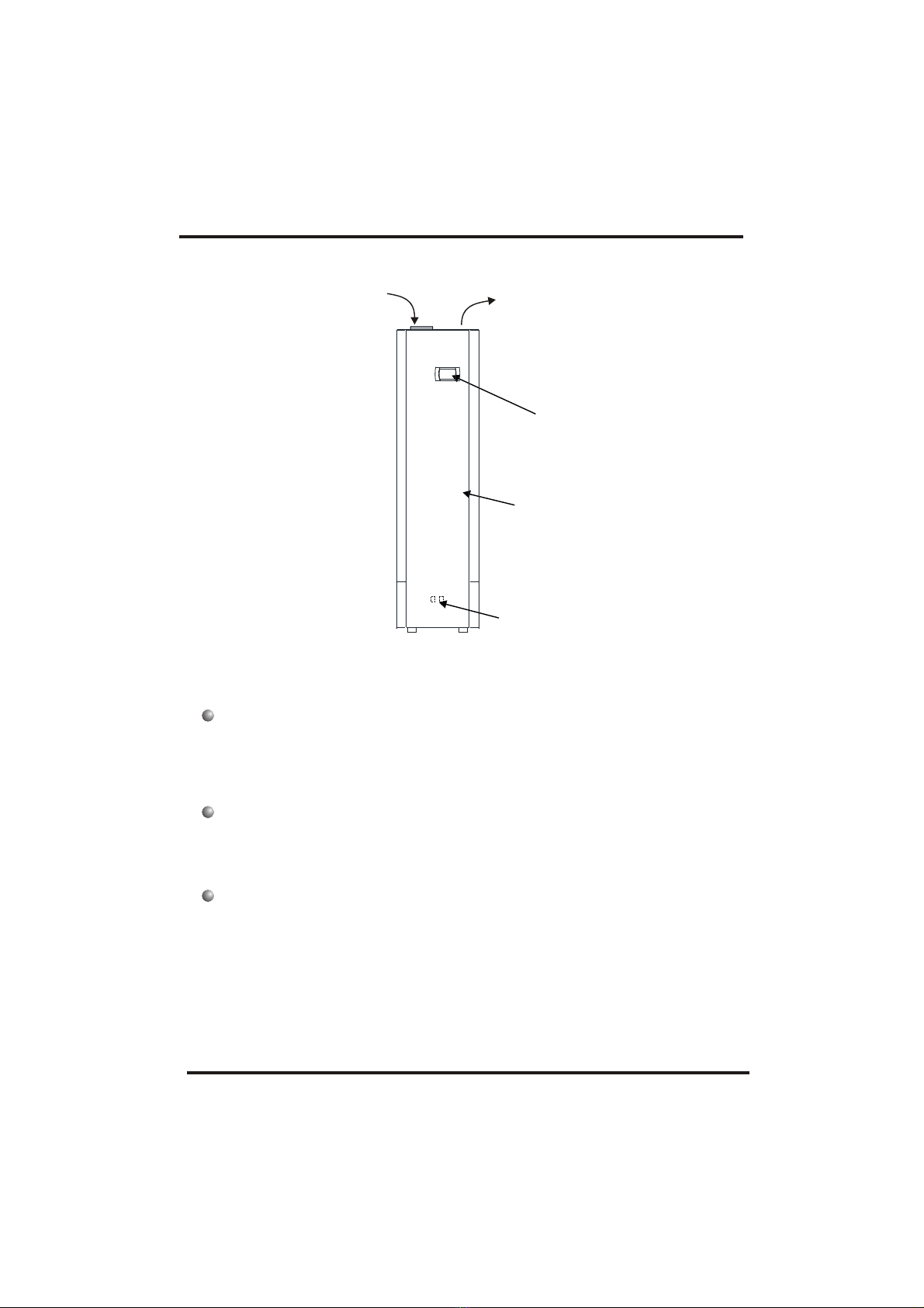
2.1 Appearance
3
2.Specs
good looking and efficient
Attractive design allows the unit to be placed in the open in finished utility spaces and
basements, reducing the cost of remodelling; depending on external condition the cost of
operation can be 25% of that of an electric water heater, and can be used in locations
unsuitable for solar hot water heating.
2.2 Characteristic
easy to operate and multiple heat sources
Contains a timer for start and stop, and an adjustment dial for easy setting of the water
temperature; depending upon the location of the air exchanger , heat may be taken from the
outside environment , from a sun porch or attic space, or from hot areas in light industrial
environments.
environmentally friendly and safer
Produces no harmful gas locally from the combustion of oil, coal, or natural gas; free of
potential hazards from carbon monoxide, it also can avoid electrical contact with water, and
does not provide an open flame, making the device more suitable for installation.
Air inlet Air outlet
Controller
Tank
Compressor
Water connections

2.3 principle
2. Specs
4
1Refrigerant is compressed into vapor with high temperature and high pressure when
it goes through the compressor.
On the discharge side of the compressor, the now hot and highly pressurized vapor
is cooled down through the heat exchange with the water in the tank until it
condenses into a high pressure, moderate temperature liquid.
Then the pressure of the liqiud refrigerant drops as it passes throttling device.
Finally, refrigerant absorbs heat from the surrounding air and evaporates into
vapor with low temperature and low pressure and then it goes into compressor
again.
The cooled surrounding air could be blew to the rooms which needs fresh cooled air.
2
3
4
5
System Principle:
Air from
outside
Hot water
Low temp.
Compressor
Compressor
Compressor
Throttling
device
Water supply
Tank
Air
exchanger Water
exchanger
High temp.
A
B
D
C
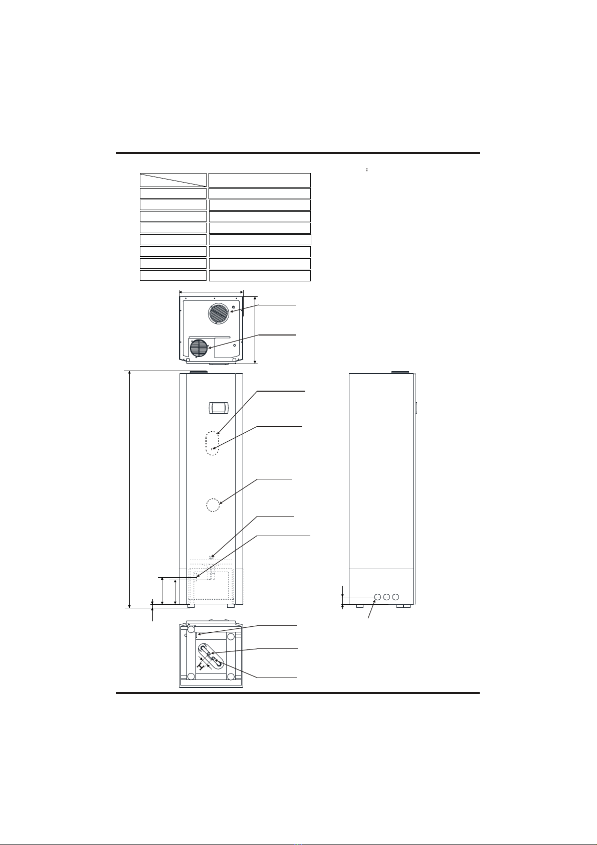
Removeable knocking down hole (when
you need to use this hole, as soon as the
center of the round is knocked, the hole
will be opened) 3 on the left and right
sides and 1 at the back, 7 in total.
5
2.Specs
2.4 Dimensions Unit mm
DimentionModel Indol Compact 200A++
C
B
Condensation
water outlet
A
Overheating
protector
Eletricity
heater
Drainage
E
F
D
G
Condensation
water outlet
Hot water
outlet
Cold water
inlet
2100
566
590
30
230
240
65
55
A
B
C
D
E
F
G
H
Magnesium
anode
Air outlet
Air inlet
6
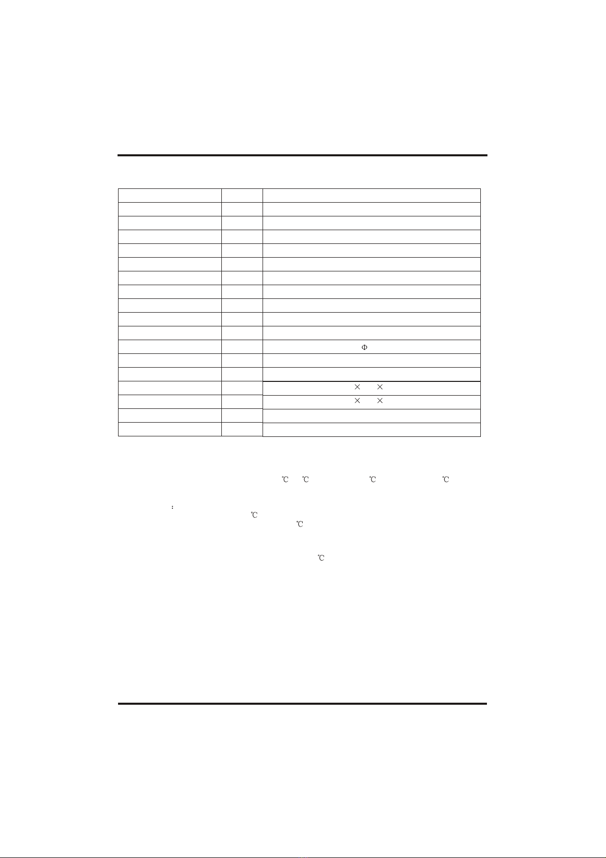
2.5 Performance Parameter
Work range
(1) Ambienttemperature is 0-40
(2) The max temperature ofwater tank is 60
Measurement conditions:
Instant heating:Ambient temperature15 /13 ,Water inlet 15 , Water outlet.45
Operating parameters
The range of the operating water temperatures: 9~60
The range of the operating water pressures: 0.15~0.7MPa
Model
Heating capacity
Water tank capacity
Power input
Running current
Power supply
Compressor Number
Compressor
Rated outlet waterTemp.
Air volume
Air pressure
Duct diameter
Water inlet/outlet size
*Auxiliary E-heater
Net dimensions
Shipping dimensions
Net weight
Shipping weight
kW
L
kW
A
¡æ
m3/h
Pa
mm
inch
kW
mm
mm
kg
kg
566 590 2100
640 680 2100
126
142
2.Specs
Indol Compact 200A++
1.8
200
0.46
2.0
1
rotary
55
350
40
150
3/4
1.5
230V~/50Hz
7
3.Function Presentation
1.Function Presentation
The unit absorbsenergy from outsideand releases the heat according to the heat
exchanger, ifthe environment temperatureis low, the heating capacity will be
attenuation.
Heating capacity
3 minutes protection
When the unitstop, if yourestart the unit or turn on the manual switch, the unit will not run
in 3 minutes,it's the protectionfor the compressor.
Defrosting
Under the heatingmode, the unitwill defrost automatic to make sure the heating
efficiency (it will last 2-10minutes).
Working condition
In order touse the unitcorrectly, please run the unit at environment temperature 0-40 .
The unit includessophisticated electronic devices,prohibited to use water from lake,
untreated river waterand groundwater!
Power off
If the powersupply is off, the unitwill stop running.If the running unit is disturbed by
lightening, car radio,power grid fluctuationsplease cut off the manualpower switch , and
then power on,press the on/ off button.
Water pressure protection
In the water system will be installed the Pressure release valve.When the tank pressure reach
0.7MPa,The Pressure release valve to open sluice
Keep power on
Always ensure thatthe unit ispowered on, you can turn off the unit, but can not power
off. If you want topower off the unit, must drain out the water in the tank.

8
4. Installation
4.1 Installation Sketch Map
Air inlet
160mm pipe
Drainage
Cold water inlet
Manual
valve
Air outlet
Condensation
water outlet
Hot water outlet
NOTE! Asafety valve MUST be installed onwater inlet!
9
4.Installation
4.2 Choose the Suitable Unit
Notice: The choice is justfor reference, pleasechoose the unitaccording to native
environment and custom.
4.3 Deposited and Transportation
As arule, the unitis to be stored and/or transported in its shipping container in upright
position and withoutwater charge. Fora transport over short distance, and provided due
care is exercised,an inclination angleof up to 30 degree is permitted. Both during
transport and storage, ambient temperatures of0 to +43 are permissible.
4.4.1 Transport using a forklift
When transported bya fork lift,the unit must remain mounted on the pallet. The lifting
rate should bekept to aminimum. Due to its top-heaviness, the unit must be secured
against tipping over. To prevent any damage, the unit must be placedon a levelsurface!
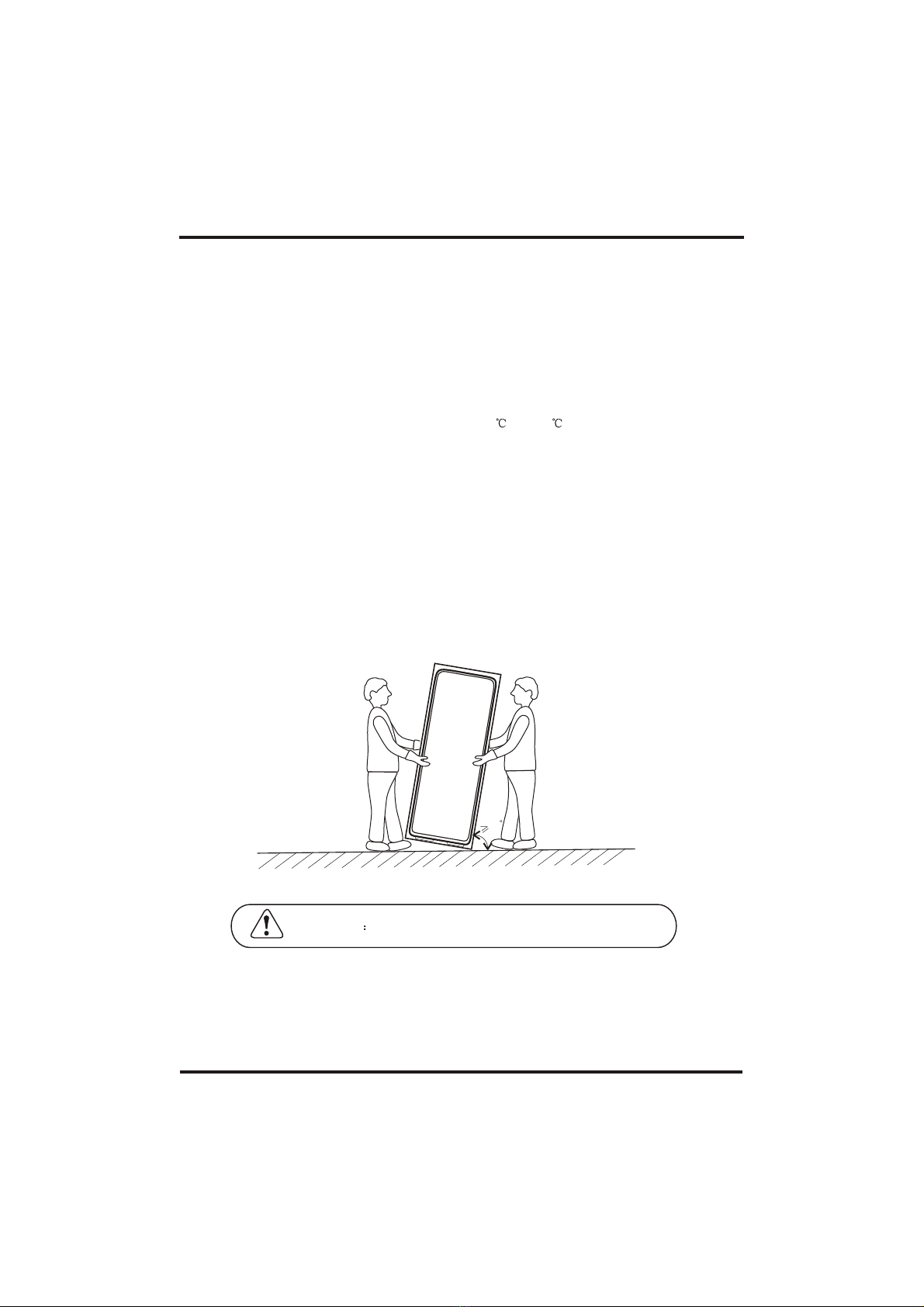
4.4.2 Manual transport
For the manualtransport, the woodenpallet can be used for bottom part. Using ropes or
carrying straps, asecond or thirdhandling configuration is possible. With this type of
handling, care mustbe taken thatthe max. Permissible inclination angle of 60 degree is
not exceeded. Iftransport in aninclined position cannot be avoided, the unit should be
taken into operationone hour afterit has been moved into final position.
CAUTION High center ofgravity, low overturning moment!
60

10
4.Installation
4.5 Installation Position
(1) Waste heat is useful heat (see picture below)
The standard heat exchanger ofthe hot-water heatpump enables directconnection to a
second heat generator, e.g. a solar heating system or a boiler.
(2) Dehumidification in the recirculating air mode (see picture below)
Dehumidified air inthe laundry roomsupports laundry drying and prevents moisture-
induced damage.

11
4.Installation
(3) Cooling in the recirculating air mode (see picture below)
The room air is extractedfrom the storage room or a wine cellar, subsequently cooled and
dehumidified in theheat pump andfinally re-introduced into the room. Recreation rooms,
boiler rooms orutility rooms areideal installation sites. The air ducts leading through warm
sections must beinsulated to preventthe formation of condensation.
1. Choose theright path tomove the unit;
2. Tryto move theunit as original case;
3. If theunit installed inthe building of the metal part, it must work for electrical
insulation and complywith the relevanttechnical standards of electrical equipment.
4.The unit doesnot include anyduct pipe, the customer also can install the duct pipe
during the installationif needed.
(4) variable change over of intake air (see picture below)
Aduct system withintegrated bypass flaps allows for variable utilization of the heat
contained in theoutside air orroom air for the production of hot water.
Installation attentions
12
4.Installation
4.5 Water Loop Connection
4.6 Wire Connection
4.7 TrialRunning
Pay attention tothese points whenconnect the water loop pipe:
Try to reduce the water loop resistance
There is wireat the bottomof the unit, it's for power supply of the unit. The spec of the wire
2
is 1.5mm .
4.8.1 Inspection beforetrial running
4.8.2 Trialrunning
The water maydrip from thedischarge pipe ofthe pressure-relief device and that this pipe
must be leftopen to theatmosphere.
Make sure thereis nothing inthe pipe andthe water loop is smooth, check the pipe
carefully to seeif there isany leak, thenpack the pipe with the insulation.
Install the oneway valve andsafety valve inthe water circulation system. The one way
valve is tobe operated regularlyto remove limedeposits and to verify that it is not blocked.
The nominal pipewidths of thefield-installed sanitary installationsmust be selectedon the
basis of theavailable water pressureand the expectedpressure drop within the piping
system. The water-side installation hasto be executedin compliance withDIN 1988(in
case of excessivewater pipe pressure,a pressure reliefvalve is to be provided!)
The water pipesmay be ofthe rigid offlexible type to prevent corrosion damage.
When installing thepipework on thecustomer's site, anycontamination of the piping
system must beavoided(pipes may haveto be flushed prior to theconnection of theunit).
There must bea switch whenconnect the unitto power system.
If the supplycord is damaged,it must be replaced by the manufacturer or our service
agent or similarlyqualified person inorder to avoida hazard.
Check the waterin the tankand the waterpipe connection.
Check the powersystem£ºmake sure the power supply isnormal and thewire connection is
Check the unit: make sure everything is ok before power on the unit, check the light on the
wire controller whenthe unit runs.
Use the wirecontroller to startthe unit;
Listen to theunit carefully whenpower on the unit, power off the unit at once when you
heard deviant noise;
Measure the water temp. to check the undulation of the water temp.;
When the parameterhas been set,the user can't change the parameter optionally, ask for
professional person tochange the parameter.
13
5. Usage
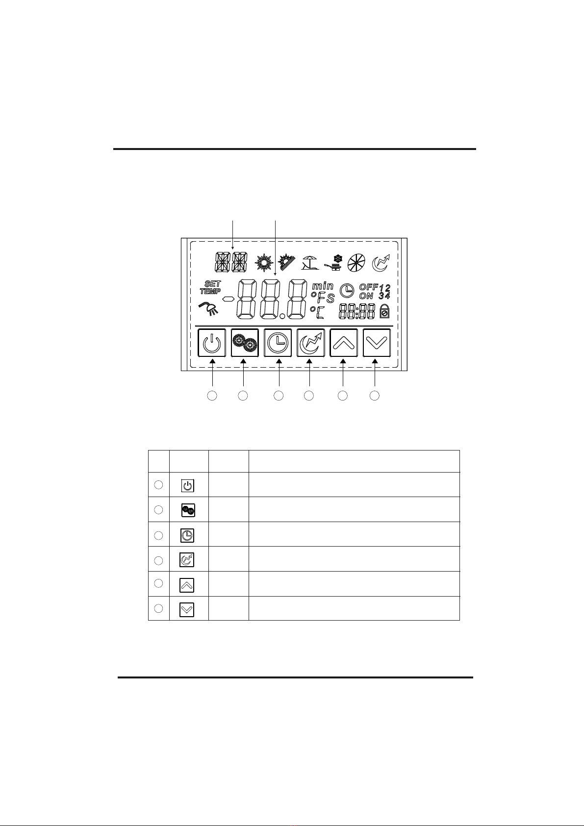
5.1 The function diagram of the wire controller
1.Function of wire controller
1£©Function ofkey
NO. Button Name Function
1
2
3
4
5
6
ON/OFF
Mode
Electric
Heater
Up
Down
Turn on/offthe unit.
Switch unit runningmodes or savesetting parameters.
Set the clockor the timer.
Turn on/offthe electric heateror switch fanmodes.
Move up orincrease parameter values.
Move down ordecrease parameter values.
Clock
Main display
area
Auxiliary display
area
1 2 3 4 5 6

14
5. Usage
Electric
heater
Fan
Shows that theelectric heater ison.
Shows that thefan is onand the speed of the fan.
Set temperature
achieved
Shows that thewater temperature hasreached the target
point and theunit shut off automatically.
Timer & ON
Timer & OFF Shows that theunit will beturned off by the timer
automatically.
Shows that theunit will beturned on by the timer
automatically.
Minute Shows that themain display areadisplays the minute.
Second Shows that themain display areadisplays the second.
Centigrade Shows that thetemperature in Maindisplay area or Auxiliary
display area isin .
Fahrenheit Shows that thetemperature in Maindisplay area or Auxiliary
display area isin .
Lock Shows that thekeyboard is locked.
Status
icon What it means
Heating
Vacation
Shows that theunit is inheating mode.
Heatpump+Electric heater
Shows that theunit is invacation mode.
ECO heating
Temperature Shows that thetemperature is non-adjustable
(measured value).
Name
Shows that theunit is inECO mode.
Heatpump only(saves mostenergy)
heating

5. Usage
15
2.Usage of wire controller
Outlet water temperature
Press " " and hold for0.5s.
Inlet water
temperature
Heating mode
Standby interface
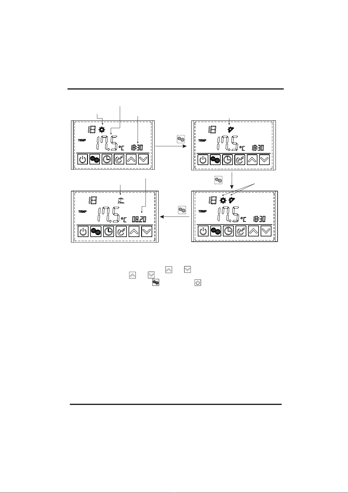
2.2 Mode selection
Press " " to select the mode from Heating ,Eco.heating , , Vacation in the
standby or runninginterface.
For example:
Intelligent
Running interface
2.1 TurnON/OFF the unit
Press " " and hold for 0.5s in the standby interface of the wire controllerto turn onthe
unit and atthis time themain display area shows the water outlet temperature.
Press " "and hold for 0.5s in the running interface of the wire controllerto turn off the
unit and atthis time themain display area shows OFF.
Note: The ON/OFF button canonly be used to turn on/off the unit in standby or running
interface of thewire controller.
5. Usage
16
Heating mode
Outlet water
temperature
Time
2.3 Target temperature checking and setting
In the standbyor running interface,press " " or " " once to check the target temperature
of the outletwater. Press " " or " " againto change the target temperature. After making
the changes tothe parameter,press " " to confirm or " " to cancel the changes, then
return to theprevious interface. Ifno operations are performed on the keypad for 5s, the
controller exits theparameter modification menuby timeout and the changes are confirmed.
Example: Change thetarget temperature from50 to 55.5 when the actual outlet water
temperature is 18¡æ.
Eco.heating mode
modeIntelligent
Press¡° ¡±
Vacation mode
Date
Press¡° ¡±
Press¡° ¡±

5. Usage
17
Outlet water temperature
Time
Target temperature
Press or again to change
the target temperature.
Press
to confirm
or to
cancel, then
return to the
previous
interface.
Press once
or
to check the
target
temperature.
Time
Press
twice then
press or
to change
the hour
parameter
and press
to confirm.
Press " " or " " to change the minute
parameter.
2.4 Timesetting
In the standbyor running interface, do as follows to set the time when in heating mode. When
press " "once, the timeparameter will flash. When press " " again, thehour parameter
will flash thenpress " "or " "to change it.After making the changes to the parameter,
press" " toconfirm, then changethe minute parameter as well as the date parameter in the
same way.
If no operationsare performed onthe keypad for 10s, the controller exits the parameter
modification menu bytimeout and thechanges are confirmed.
Note: Set the datein the sameway when in vacation mode.
Example: Change thetime and datefrom 18:30 on August 4th to 17:40 on September 8th.
Other manuals for 200A++
1
Table of contents
Other Indol Heat Pump manuals


Popular Heat Pump manuals by other brands


Carrier
Carrier DHMVHA Service manual

Midea
Midea V4 Plus S Series Technical & service manual

Mitsubishi Electric
Mitsubishi Electric ecodan EHPT series Operation manual for user

FHP
FHP EV Series Installation and maintenance manual

Bosch
Bosch Compress 2000 AWF Installation and operating instructions

Lennox
Lennox ELP Series user manual

Trane
Trane 4TWR3 Installer's guide

Carrier
Carrier Comfort 25HCR3C Product data

Sanden
Sanden GAUS-160FQS owner's manual

Mitsubishi Electric
Mitsubishi Electric Ecodan Homeowner quick start guide

Daikin
Daikin EHBH04CA3V Operation manual

Mitsubishi Electric
Mitsubishi Electric City Multi PUHY-P168TSJMU-A datasheet