manuals.online logo
Brands
  1. Home
  2. •
  3. Brands
  4. •
  5. Panasonic
  6. •
  7. Heat Pump
  8. •
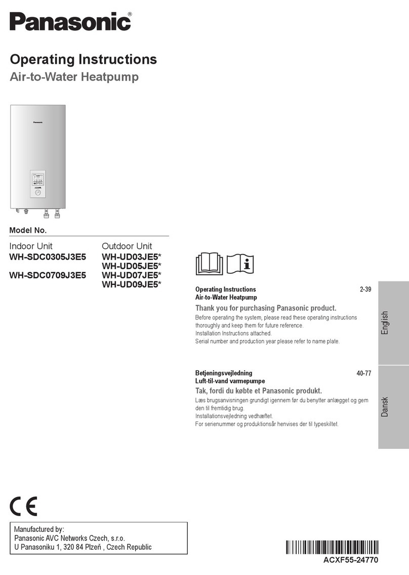
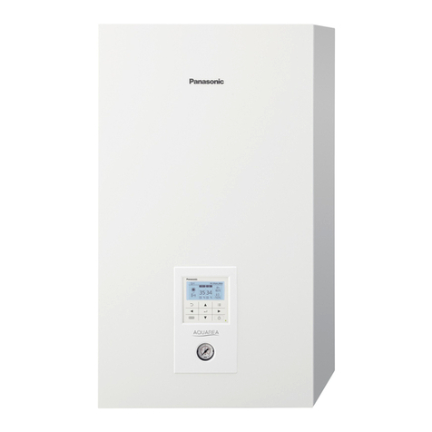
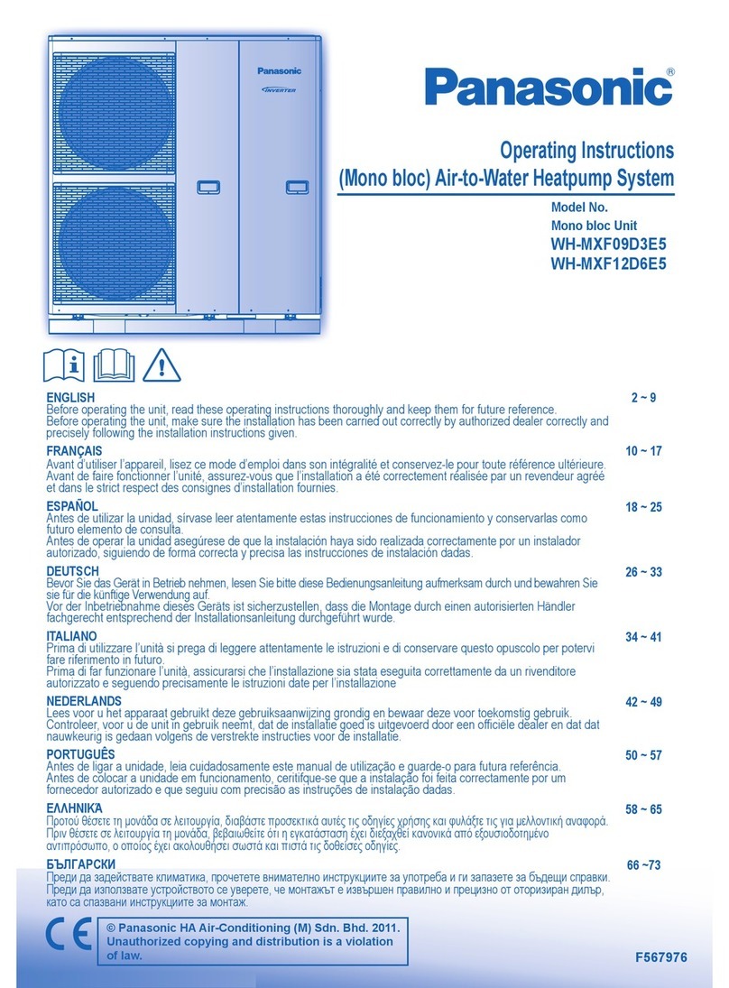
  9. Panasonic WH-MXC09J3E5 User manual

Panasonic WH-MXC09J3E5 User manual

8. Removal and evacuation
• When breaking into the refrigerant circuit to make repairs – or for any other purpose – conventional procedures shall be used.
However, it is important that best practice is followed since flammability is a consideration.
The following procedure shall be adhered to:
• remove refrigerant -> • purge the circuit with inert gas -> • evacuate -> • purge with inert gas -> • open the circuit by cutting or brazing
• The refrigerant charge shall be recovered into the correct recovery cylinders.
• The system shall be purged with OFN to render the appliances safe. (remark: OFN = oxygen free nitrogen, type of inert gas)
• This process may need to be repeated several times.
• Compressed air or oxygen shall not be used for this task.
• Purging shall be achieved by breaking the vacuum in the system with OFN and continuing to fill until the working pressure is achieved, then venting to atmosphere, and finally pulling down to a vacuum.
• This process shall be repeated until no refrigerant is within the system.
• When the final OFN charge is used, the system shall be vented down to atmospheric pressure to enable work to take place.
• This operation is absolutely vital if brazing operations on the pipe work are to take place.
• Ensure that the outlet for the vacuum pump is not close to any potential ignition sources and there is ventilation available.
9. Charging procedures
• In addition to conventional charging procedures, the following requirements shall be followed.
- Ensure that contamination of different refrigerants does not occur when using charging equipment.
- Hoses or lines shall be as short as possible to minimize the amount of refrigerant contained in them.
- Cylinders shall be kept in an appropriate position according to the instructions.
- Ensure that the refrigerating system is earthed prior to charging the system with refrigerant.
- Label the system when charging is complete (if not already).
- Extreme care shall be taken not to over fill the refrigerating system.
• Prior to recharging the system it shall be pressure tested with OFN (refer to #7).
• The system shall be leak tested on completion of charging but prior to commissioning.
• A follow up leak test shall be carried out prior to leaving the site.
• Electrostatic charge may accumulate and create a hazardous condition when charging and discharging the refrigerant.
To avoid fire or explosion, dissipate static electricity during transfer by grounding and bonding containers and equipment before charging/discharging.
10.
Decommissioning
• Before carrying out this procedure, it is essential that the technician is completely familiar with the equipment and all its details.
• It is recommended good practice that all refrigerants are recovered safely.
• Prior to the task being carried out, an oil and refrigerant sample shall be taken in case analysis is required prior to re-use of recovered refrigerant.
• It is essential that electrical power is available before the task is commenced.
a) Become familiar with the equipment and its operation.
b) Isolate system electrically.
c) Before attempting the procedure ensure that:
f) Make sure that cylinder is situated on the scales before recovery takes place.
g) Start the recovery machine and operate in accordance with instructions.
h) Do not over fill cylinders. (No more than 80 % volume liquid charge).
i) Do not exceed the maximum working pressure of the cylinder, even temporarily.
j) When the cylinders have been filled correctly and the process completed, make sure that the
cylinders and the equipment are removed from site promptly and all isolation valves on the equipment
are closed off.
k) Recovered refrigerant shall not be charged into another refrigerating system unless it has been
cleaned and checked.
• mechanical handling equipment is available, if required, for handling refrigerant cylinders;
• all personal protective equipment is available and being used correctly;
• the recovery process is supervised at all times by a competent person;
• recovery equipment and cylinders conform to the appropriate standards.
d) Pump down refrigerant system, if possible.
e) If a vacuum is not possible, make a manifold so that refrigerant can be removed from various
parts of the system.
• Electrostatic charge may accumulate and create a hazardous condition when charging or discharging the refrigerant.
To avoid fire or explosion, dissipate static electricity during transfer by grounding and bonding containers and equipment before charging/discharging.
11.
Labelling
• Equipment shall be labelled stating that it has been de-commissioned and emptied of refrigerant.
• The label shall be dated and signed.
• Ensure that there are labels on the equipment stating the equipment contains flammable refrigerant.
12.
Recovery
• When removing refrigerant from a system, either for servicing or decommissioning, it is recommended good practice that all refrigerants are removed safely.
• When transferring refrigerant into cylinders, ensure that only appropriate refrigerant recovery cylinders are employed.
• Ensure that the correct number of cylinders for holding the total system charge are available.
• All cylinders to be used are designated for the recovered refrigerant and labelled for that refrigerant (i.e. special cylinders for the recovery of refrigerant).
• Cylinders shall be complete with pressure relief valve and associated shut-off valves in good working order.
• Recovery cylinders are evacuated and, if possible, cooled before recovery occurs.
• The recovery equipment shall be in good working order with a set of instructions concerning the equipment that is at hand and shall be suitable for the recovery of flammable refrigerants.
• In addition, a set of calibrated weighing scales shall be available and in good working order.
• Hoses shall be complete with leak-free disconnect couplings and in good condition.
• Before using the recovery machine, check that it is in satisfactory working order, has been properly maintained and that any associated electrical components are sealed to prevent ignition in the event of a
refrigerant release.
Consult manufacturer if in doubt.
• The recovered refrigerant shall be returned to the refrigerant supplier in the correct recovery cylinder, and the relevant Waste Transfer Note arranged.
• Do not mix refrigerants in recovery units and especially not in cylinders.
• If compressors or compressor oils are to be removed, ensure that they have been evacuated to an acceptable level to make certain that flammable refrigerant does not remain within the lubricant.
• The evacuation process shall be carried out prior to returning the compressor to the suppliers.
• Only electric heating to the compressor body shall be employed to accelerate this process.
• When oil is drained from a system, it shall be carried out safely.
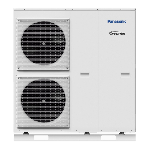
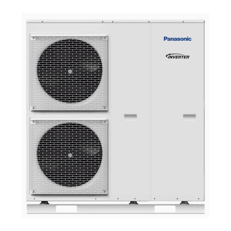
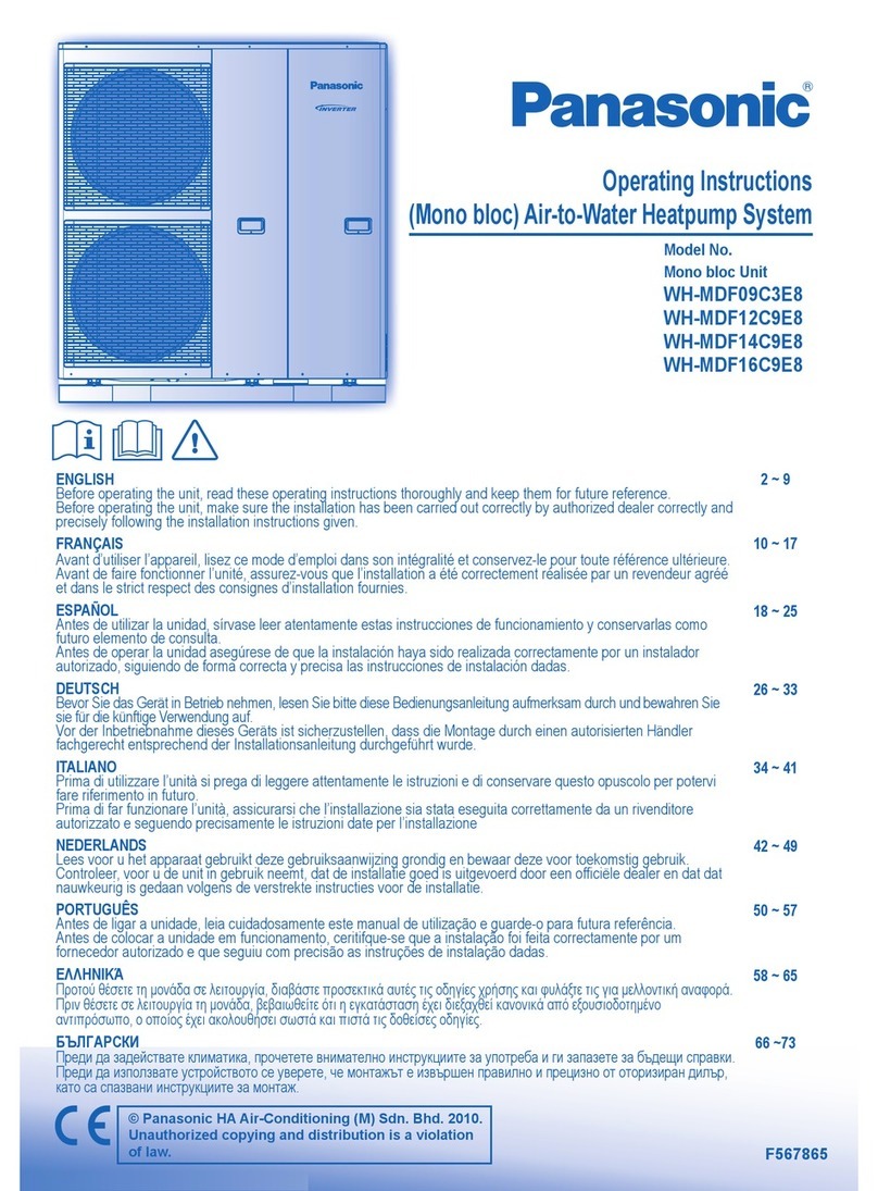
Handling of Mono bloc unit
Mono bloc unit is a large and heavy apparatus. The handling of the unit only to be done
by lifting tools with slings.These slings can be fitted into sleeves at the unit’s base frame.
Attached Accessories
No. Accessories part Qty.
1Drain elbow 1
2Rubber cap 8
3
Remote controller
1
Optional Accessory
No. Accessories part Qty.
4Optional PCB (CZ-NS4P) 1
5Base Pan Heater (CZ-NE3P) 1
6Network Adaptor (CZ-TAW1) 1
7Network Adaptor Cable (CZ-TAW1-CBL) 1
Field Supply Accessories (Optional)
No. Part Model Specification Maker
i 2-way valve kit Electromotoric Actuator SFA21/18 AC230V Siemens
2-port Valve VVI46/25 - Siemens
ii 3-way valve kit Electromotoric Actuator SFA21/18 AC230V Siemens
3-port Valve VXI46/25 - Siemens
iii Room thermostat Wired PAW-A2W-RTWIRED AC230V -
Wireless PAW-A2W-RTWIRELESS
iv Mixing valve - 167032 AC230V Caleffi
v Pump - Yonos 25/6 AC230V Wilo
vi Buffer tank sensor - PAW-A2W-TSBU - -
vii Outdoor sensor - PAW-A2W-TSOD - -
viii Zone water sensor - PAW-A2W-TSHC - -
ix Zone room sensor - PAW-A2W-TSRT - -
x Solar sensor - PAW-A2W-TSSO - -

It is recommended to purchase the field supply accessories listed in above table.
SAFETY PRECAUTIONS
•
Read the following “SAFETY PRECAUTIONS” carefully before installation of (Mono bloc) Air-to-Water Heatpump system (hereafter referred to as “Mono bloc unit”).
•
Electrical works and water installation works must be done by licensed electrician and licensed water system installer respectively. Be sure to use the correct rating and
main circuit for the model to be installed.
•
The caution items stated here must be followed because these important contents are related to safety. The meaning of each indication used is as below.
Incorrect installation due to ignorance or negligence of the instructions will cause harm or damage, and the seriousness is classified by the following indications.
WARNING
This indication shows the possibility of causing death or serious injury.
CAUTION
This indication shows the possibility of causing injury or damage to properties only.
The items to be followed are classified by the symbols:
Symbol with white background denotes item that is PROHIBITED.
Symbol with dark background denotes item that must be carried out.
•
Carry out test run to confirm that no abnormality occurs after the installation. Then, explain to user the operation, care and maintenance as stated in instructions. Please
remind the customer to keep the operating instructions for future reference.
•
If there is any doubt about the installation procedure or operation, always contact the authorized dealer for advice and information.
•
This appliance is not intended for accessibility by the general public.
•
Please leave this installation manual to the user after installation.
ACXF60-41770-AA
Required tools for Installation Works
1 Phillips screw driver
2 Level gauge
3 Electric drill
4 Spanner
5 Knife
6 Gas leak detector
7 Measuring tape
8 Megameter
9 Multimeter
10 Torque wrench
117.6 N•m (11.6 kgf•m)
11 Vacuum pump
12 Gauge manifold
CAUTION
R32
REFRIGERANT
This AIR-TO-WATER HEATPUMP MONO
BLOC contains and operates with
refrigerant R32.
THIS PRODUCT MUST ONLY BE INSTALLED OR SERVICED
BY QUALIFIED PERSONNEL.
Refer to National, State, Territory and local legislation,
regulations, codes, installation & operation manuals, before
the installation, maintenance and/or service of this product.
Explanation of symbols displayed on the indoor unit or outdoor unit.
WARNING
This symbol shows that this equipment uses a flammable
refrigerant. If the refrigerant is leaked, together with an external
ignition source, there is a possibility of ignition.
CAUTION
This symbol shows that the Installation Manual should be read
carefully.
CAUTION
This symbol shows that a service personnel should be handling
this equipment with reference to the Installation Manual.
CAUTION
This symbol shows that there is information included in the
Operation Manual and/or Installation Manual.
Installation Manual
AIR-TO-WATER HEATPUMP MONO BLOC
WH-MXC09J3E5, WH-MXC12J6E5
Main Components
WARNING
Since the working pressure is higher than that of refrigerant R22 models, some of the piping and installation and service tools are special.
Especially, when replacing a refrigerant R22 model with a new refrigerant R32 model, always replace the conventional piping with the R32 and R410A piping on the outdoor unit side.
For R32 and R410A, the same pipe can be used.
The mixing of different refrigerants within a system is prohibited. Models that use refrigerant R32 and R410A have a different charging port thread diameter to prevent erroneous charging with refrigerant R22 and for
safety.
Therefore, check beforehand. [The charging port thread diameter for R32 and R410A is 12.7 mm (1/2 inch).]
Ensure that foreign matter (oil, water, etc.) does not enter the piping.
Operation, maintenance, repairing and refrigerant recovery should be carried out by trained and certified personnel in the use of flammable refrigerants and as recommended by the manufacturer. Any personnel
conducting an operation, servicing or maintenance on a system or associated parts of the equipment should be trained and certified.
Any part of refrigerating circuit (evaporators, air coolers, AHU, condensers or liquid receivers) or piping should not be located in the proximity of heat sources, open flames, operating gas appliance or an operating
electric heater.
The user/owner or their authorized representative shall regularly check the alarms, mechanical ventilation and detectors, at least once a year, where as required by national regulations, to ensure their correct functioning.
A logbook shall be maintained. The results of these checks shall be recorded in the logbook.
In case of ventilations in occupied spaces shall be checked to confirm no obstruction.
Before a new refrigerating system is put into service, the person responsible for placing the system in operation should ensure that trained and certified operating personnel are instructed on the basis of the instruction
manual about the construction, supervision, operation and maintenance of the refrigerating system, as well as the safety measures to be observed, and the properties and handling of the refrigerant used.
The general requirement of trained and certified personnel are indicated as below:
a)Knowledge of legislation, regulations and standards relating to flammable refrigerants; and,
b)Detailed knowledge of and skills in handling flammable refrigerants, personal protective equipment, refrigerant leakage prevention, handling of cylinders, charging, leak detection, recovery and disposal; and,
c)Able to understand and to apply in practice the requirements in the national legislation, regulations and Standards; and,
d)Continuously undergo regular and further training to maintain this expertise.
Protect the refrigerating system from accidental rupture due to moving furniture or reconstruction activities.
To ensure no leaking, refrigerant joints shall be tightness tested. The test method shall have a sensitivity of 5 grams per year of refrigerant or better under a pressure of at least 0,25 times the maximum allowable
pressure (>1.04MPa, max 4.3MPa). No leak shall be detected.
CAUTION
1.
Installation (Space)
• Must comply with national gas regulations, state municipal rules and legislation. Notify relevant authorities in accordance with all applicable regulations.
• Must ensure mechanical connections be accessible for maintenance purposes.
• In cases that require mechanical ventilation, ventilation openings shall be kept clear of obstruction.
• When disposal of the product, do follow to the precautions in #12 and comply with national regulations.
• Always contact to local municipal offices for proper handling.
2.
Servicing
2-1. Service personnel
• Any qualified person who is involved with working on or breaking into a refrigerant circuit should hold a current valid certificate from an industry-accredited assessment authority, which authorizes their
competence to handle refrigerants safely in accordance with an industry recognized assessment specification.
• Servicing shall only be performed as recommended by the equipment manufacturer. Maintenance and repair requiring the assistance of other skilled personnel shall be carried out under the supervision of the
person competent in the use of flammable refrigerants.
• Servicing shall be performed only as recommended by the manufacturer.
•
The system is inspected, regularly supervised and maintained by a trained and certified service personnel who is employed by the person user or party responsible.
• Ensure refrigerant charge not to leak.
2-2. Work
• Prior to beginning work on systems containing flammable refrigerants, safety checks are necessary to ensure that the risk of ignition is minimised.
For repair to the refrigerating system, the precautions in #2-2 to #2-8 must be followed before conducting work on the system.
• Work shall be undertaken under a controlled procedure so as to minimize the risk of a flammable gas or vapour being present while the work is being performed.
• All maintenance staff and others working in the local area shall be instructed and supervised on the nature of work being carried out.
• Avoid working in confined spaces. Always ensure away from source, at least 2 meter of safety distance, or zoning of free space area of at least 2 meter in radius.
• Wear appropriate protective equipment, including respiratory protection, as conditions warrant.
•
Keep all sources of ignition and hot metal surfaces away.
2-3. Checking for presence of refrigerant
• The area shall be checked with an appropriate refrigerant detector prior to and during work, to ensure the technician is aware of potentially flammable atmospheres.
• Ensure that the leak detection equipment being used is suitable for use with flammable refrigerants, i.e. non sparking, adequately sealed or intrinsically safe.
• In case of leakage/spillage happened, immediately ventilate area and stay upwind and away from spill/release.
• In case of leakage/spillage happened, do notify persons down wind of the leaking/spill, isolate immediate hazard area and keep unauthorized personnel out.
2-4. Presence of fire extinguisher
• If any hot work is to be conducted on the refrigerating equipment or any associated parts, appropriate fire extinguishing equipment shall be available at hand.
• Have a dry powder or CO2fire extinguisher adjacent to the charging area.
2-5. No ignition sources
• No person carrying out work in relation to a refrigerating system which involves exposing any pipe work that contains or has contained flammable refrigerant shall use any sources of ignition in such a manner that
it may lead to the risk of fire or explosion. He/She must not be smoking when carrying out such work.
• All possible ignition sources, including cigarette smoking, should be kept sufficiently far away from the site of installation, repairing, removing and disposal, during which flammable refrigerant can possibly be
released to the surrounding space.
• Prior to work taking place, the area around the equipment is to be surveyed to make sure that there are no flammable hazards or ignition risks.
• “No Smoking” signs shall be displayed.
2-6.Ventilated area
• Ensure that the area is in the open or that it is adequately ventilated before breaking into the system or conducting any hot work.
• A degree of ventilation shall continue during the period that the work is carried out.
• The ventilation should safely disperse any released refrigerant and preferably expel it externally into the atmosphere.
2-7. Checks to the refrigerating equipment
• Where electrical components are being changed, they shall be fit for the purpose and to the correct specification.
• At all times the manufacturer’s maintenance and service guidelines shall be followed.
• If in doubt consult the manufacturer’s technical department for assistance.
• The following checks shall be applied to installations using flammable refrigerants.
- The ventilation machinery and outlets are operating adequately and are not obstructed.
- Marking to the equipment continues to be visible and legible. Markings and signs that are illegible shall be corrected.
2-8. Checks to electrical devices
• Repair and maintenance to electrical components shall include initial safety checks and component inspection procedures.
• Initial safety checks shall include but not limit to:-
- That capacitors are discharged: this shall be done in a safe manner to avoid possibility of sparking.
- That there is no live electrical components and wiring are exposed while charging, recovering or purging the system.
- That there is continuity of earth bonding.
• At all times the manufacturer’s maintenance and service guidelines shall be followed.
• If in doubt consult the manufacturer’s technical department for assistance.
• If a fault exists that could compromise safety, then no electrical supply shall be connected to the circuit until it is satisfactorily dealt with.
• If the fault cannot be corrected immediately but it is necessary to continue operation, an adequate temporary solution shall be used.
• The owner of the equipment must be informed or reported so all parties are advised thereinafter.
3.
Repairs to sealed components
•
During repairs to sealed components, all electrical supplies shall be disconnected from the equipment being worked upon prior to any removal of sealed covers, etc.
• If it is absolutely necessary to have an electrical supply to equipment during servicing, then a permanently operating form of leak detection shall be located at the most critical point to warn of a potentially
hazardous situation.
• Particular attention shall be paid to the following to ensure that by working on electrical components, the casing is not altered in such a way that the level of protection is affected. This shall include damage
to cables, excessive number of connections, terminals not made to original specification, damage to seals, incorrect fitting of glands, etc.
• Ensure that apparatus is mounted securely.
• Ensure that seals or sealing materials have not degraded such that they no longer serve the purpose of preventing the ingress of flammable atmospheres.
• Replacement parts shall be in accordance with the manufacturer’s specifications.
NOTE: The use of silicon sealant may inhibit the effectiveness of some types of leak detection equipment.
Intrinsically safe components do not have to be isolated prior to working on them.
4.
Repair to intrinsically safe components
• Do not apply any permanent inductive or capacitance loads to the circuit without ensuring that this will not exceed the permissible voltage and current permitted for the equipment in use.
• Intrinsically safe components are the only types that can be worked on while live in the presence of a flammable atmosphere.
• The test apparatus shall be at the correct rating.
•
Replace components only with parts specified by the manufacturer. Unspecified parts by manufacturer may result ignition of refrigerant in the atmosphere from a leak.
5.
Cabling
• Check that cabling will not be subject to wear, corrosion, excessive pressure, vibration, sharp edges or any other adverse environmental effects.
• The check shall also take into account the effects of aging or continual vibration from sources such as compressors or fans.
6.
Detection of flammable refrigerants
• Under no circumstances shall potential sources of ignition be used in the searching or detection of refrigerant leaks.
• A halide torch (or any other detector using a naked flame) shall not be used.
7.
The following leak detection methods are deemed acceptable for all refrigerant systems.
• No leaks shall be detected when using detection equipment with a sensitivity of 5 grams per year of refrigerant or better under a pressure of at least 0,25 times the maximum allowable pressure (>1.04MPa, max
4.3MPa). For example, a universal sniffer.
• Electronic leak detectors may be used to detect flammable refrigerants, but the sensitivity may not be adequate, or may need re-calibration.
(Detection equipment shall be calibrated in a refrigerant-free area.)
• Ensure that the detector is not a potential source of ignition and is suitable for the refrigerant used.
• Leak detection equipment shall be set at a percentage of the LFL of the refrigerant and shall be calibrated to the refrigerant employed and the appropriate percentage of gas (25 % maximum) is confirmed.
• Leak detection fluids are also suitable for use with most refrigerants, for example, bubble method and fluorescent method agents. The use of detergents containing chlorine shall be avoided as the chlorine may
react with the refrigerant and corrode the copper pipe-work.
• If a leak is suspected, all naked flames shall be removed/extinguished.
• If a leakage of refrigerant is found which requires brazing, all of the refrigerant shall be recovered from the system, or isolated (by means of shut off valves) in a part of the system remote from the leak.
The precautions in #8 must be followed to remove the refrigerant.
PRECAUTION FOR USING R32 REFRIGERANT
• The basic installation work procedures are the same as conventional refrigerant (R410A, R22) models.
However, pay careful attention to the following points:
WARNING
Do not use means to accelerate the defrosting process or to clean, other than those recommended by the manufacturer. Any unfit method or using incompatible
material may cause product damage, burst and serious injury.
Do not install Mono bloc unit near handrail of veranda. When installing Mono bloc unit at veranda of high rise building, child may climb up to Mono bloc unit and
cross over the handrail and causing accident.
Do not use unspecified cord, modified cord, joint cord or extension cord for power supply cord. Do not share the single outlet with other electrical appliances. Poor
contact, poor insulation or over current will cause electrical shock or fire.
Do not tie up the power supply cord into a bundle by band. Abnormal temperature rise on power supply cord may happen.
Do not insert your fingers or other objects into the unit, high speed rotating fan may cause injury.
Do not sit or step on the unit, you may fall down accidentally.
Keep plastic bag (packaging material) away from small children, it may cling to nose and mouth and prevent breathing.
Do not purchase unauthorized electrical parts for installation, service, maintenance and etc.. They might cause electrical shock or fire.
Do not pierce or burn as the appliance is pressurized. Do not expose the appliance to heat, flame, sparks, or other sources of ignition. Else, it may explode and
cause injury or death.
This Mono bloc unit is a multi supply appliance. All circuits must be disconnected before accessing the unit terminals.
Do not modify the wiring of Mono bloc unit for installation of other components (i.e. heater, etc). Overloaded wiring or wire connection points may cause electrical
shock or fire.
Do not add or replace refrigerant other than specified type. It may cause product damage, burst and injury etc.
For electrical work, follow the national regulation, legislation and this installation instructions. An independent circuit and single outlet must be used. If electrical
circuit capacity is not enough or defect found in the electrical work, it will cause electrical shock or fire.
For water circuit installation work, follow to relevant European and national regulations (including EN61770) and local plumbing and building regulation codes.
Engage authorized dealer or specialist for installation. If installation done by the user is incorrect, it will cause water leakage, electrical shock or fire.
Install according to this installation instructions strictly. If installation is defective, it will cause water leakage, electrical shock or fire.
Only use the supplied or specified installation parts. Else, it may causes Mono bloc unit vibrate, fall, water leakage, electrical shock or fire.
Install at a flat, strong and firm location which is able to withstand the Mono bloc unit’s weight. If the location is slanting, or strength is not enough the set will fall
and cause injury.
Wire routing must be properly arranged so that control board cover is fixed properly. If control board cover is not fixed perfectly, it will cause fire or electrical shock.
This equipment is strongly recommended to be installed with Residual Current Device (RCD) on-site according to the respective national wiring rules or country-
specific safety measures in terms of residual current.
The unit is only for use in a closed water system. Utilization in an open water system may lead to excessive corrosion of the water piping and risk of incubating
bacteria colonies, particularly Legionella, in water.
If there is any doubt about the installation procedure or operation, always contact the authorized dealer for advice and information.
Select a location where in case of water leakage, the leakage will not cause damage to other properties.
When installing electrical equipment at wooden building of metal lath or wire lath, in accordance with electrical facility standard, no electrical contact between
equipment and building is allowed. Insulator must be installed in between.
This installation may be subjected to building regulation approval applicable to respective country that may require to notify the local authority before installation.
Any work carried out on the Mono bloc unit after removing any panel which is secured by screws, must be carried out under the supervision of authorized dealer
and licensed installation contractor.
Be aware that refrigerants may not contain an odour.
This equipment must be properly earthed. Earth line must not be connected to gas pipe, water pipe, earth of lightning rod and telephone. Otherwise, it may cause
electrical shock in case of equipment breakdown or insulation breakdown.
CAUTION
Do not install the Mono bloc unit at place where leakage of flammable gas may occur. In case gas leaks and accumulates at surrounding of the Mono bloc unit,
it may cause fire.
Do not release refrigerant during piping work for installation, re-installation and during repairing a refrigeration parts. Take care of the liquid refrigerant, it may
cause frostbite.
Make sure the insulation of power supply cord does not contact hot part (i.e. refrigerant piping, water piping) to prevent from insulation failure (melt).
Do not touch the sharp aluminium fin, sharp parts may cause injury.
Do not apply excessive force to water pipes that may damage the pipes. If water leakage occurs, it will cause flooding and damage to other properties.
Carry out drainage piping as mentioned in installation instructions. If drainage is not perfect, water leakage may happen and may cause damage to properties of
the user.
The piping installation work must be flushed before the Mono bloc unit is connected to remove contaminants. Contaminants may damage the Mono bloc unit
components.
Select an installation location which is easy for maintenance. Incorrect installation, service or repair of this Mono bloc unit may increase the risk of rupture and this
may result in loss damage or injury and/or property.
Ensure the correct polarity is maintained throughout all wiring. Otherwise, it will cause electrical shock or fire.
Power supply connection to Mono bloc unit.
•
Power supply point should be in easily accessible place for power disconnection in case of emergency.
•
Must follow local national wiring standard, regulation and this installation instruction.
•
Strongly recommended to make permanent connection to a circuit breaker. It must be a double pole switch with a minimum 3.0 mm gap.
-Power supply 1: Use approved 30A circuit breaker
-Power supply 2: Use approved 30A circuit breaker
Ensure the correct polarity is maintained throughout all wiring. Otherwise, it will cause electrical shock or fire.
After installation, the installer is obliged to verify correct operation of the Mono bloc unit. Check the connection point for water leakage during test run. If leakage
occurs, it will cause damage to other properties.
Keep any required ventilation openings clear of obstruction.
Installation work.
Four or more people are required to carry out the installation work. The weight of Mono bloc unit might cause injury if carried by less than four people.
Dimension Diagram
CAUTION
240-250V
2-1
A
b
a
2-2
Rear view
Side viewFront view
1284
980 152
63
73
405
195
25
400
20 103
30
59 322
1340
1410
Bottom view
Drain hose
connector
100mm
or more
300mm
or more
300mm
or more
1000mm
or more
Water Outlet Pipe
Water Inlet Pipe
Component name
1 PCB
2-1 Single phase RCCB (Main Power)
2-2 Single phase RCCB (Backup Heater)
3Heat Exchanger
4Water Pressure gauge
5Water pump
6Cabinet top plate
7Expansion vessel (Not Visible)
8Flow sensor
9Heater assembly
0Overload protector
aPressure relief valve
bAir purge valve
cWater Filter Set
dPlug (2 pieces)
eBushing (6 pieces)
fCabinet front plate
gCover
Connector name
aWater inlet
bWater outlet
DETAIL A
FOR
WH-MXC12J6E5
DETAIL A
FOR
WH-MXC09J3E5
61
0 0
b
4
8
9
3
7
a
c
5
e
d
f
g
It is advisable to avoid more than 2 blockage directions. For better ventilation
& multiple-outdoor installation, please consult authorized dealer/specialist.
ENGLISH
ACXF60-41770-AA
PRINTED IN MALAYSIA
1/36
TEST RUN
1. Before test run, make sure below items have been checked:-
a) Pipework are properly done.
b) Electric cable connecting work are properly done.
c) Mono bloc unit is filled up with water and trapped air is released.
2. Antifreeze agent must be added into water circuit to prevent freezing of water when outdoor ambient temperatures is low. Recommended antifreeze:
Propylene glycol: 40% (equivalent to -20°C)
3. Set ON to the Mono bloc unit and RCCB 2. Then, for remote control operation please refers to (Mono bloc) Air-to-Water Heatpump’s operation instruction.
Note:
•
During winter, turn on the power supply and standby the unit for at least 15 minutes before test run.
Allow sufficient time to warm up refrigerant and prevent wrong error code judgement.
4. For normal operation, Water Pressure Gauge 4reading should be in between 0.05 MPa and 0.3 MPa.
5. After test run, please clean the Magnetic Water Filter Set c. Reinstall it after finish cleaning.
CHECK WATER FLOW OF WATER CIRCUIT
Confirm the maximum water flow during main pump operation not less than 15 l/min.
*Water flow can be check through service setup (Pump Max Speed)
[Heating operation at low water temperature with lower water flow may trigger “H75” during defrost process.]
RESET OVERLOAD PROTECTOR 0
Overload Protector 0serves the safety purpose to prevent the water over heating. When the Overload Protector 0trip
at high water temperature, take below steps to reset it.
1. Take out the cover.
2. Use a test pen to push the centre button gently in order to reset the Overload Protector 0.
3. Fix the cover to the original fixing condition.
TEST RUN
9
Use test pen to push this
button for reset Overload
Protector 0.
Mono bloc unit will become heavy when filled with water. Please install the unit on a strong concrete floor and consider the
weight of the unit and water.
•
Fix Mono bloc unit on the concrete floor with M12 anchor bolt at 4 locations.
•
Pull-out strength of these anchor bolts must be above 15000N.
Grip anchor bolt Embedded anchor bolt
Broken stone
Anchor bolt 60mm
or more
300mm
or more
Floor
Concrete
Anchor bolt
Floor slab (concrete)
Above
20mm
80mm
•
Compress strength of concrete is above 18MPa {180kgf/cm2}
Illustration of grip type and embedded type anchor bolt
DISPOSAL OF MONO BLOC UNIT DRAIN WATER
•
When a Drain elbow 1is used, please ensure to follow below:
-The unit should be placed on a stand which is taller than 50mm.
-Cover the 8 holes (ø20mm) with Rubber cap 2(refer to illustration below)
-Use a tray (field supply) when necessary to dispose the Mono bloc unit drain water.
Drain elbow 1
Rubber cap 2x 8
•
If the unit is used in an area where temperature falls below 0°C for 2 or 3 consecutive days, it is recommended not to use
the Drain elbow 1and Rubber cap 2, for the drain water freezes and the fan will not rotate.
MONO BLOC UNIT INSTALLATION
2
PIPING INSTALLATION
3
WARNING
This section is for authorized and licensed electrician / water system installer only. Work behind the Cabinet Front Plate fsecured by screws must only be carried out under supervision of qualified contractor,
installation engineer or service person.
Temporary connection to be
removed immediately after filling
Servicing
Valve
Fan Coil Unit
2-Way Valve
Tank
Radiator /
Floor Heater
Servicing
Valve
Main Water
Supply
Double Check Valve assembly
is acceptable in house
Typical Piping Installation
Please engage a licensed water circuit installer to install this water circuit.
• This water circuit must comply with relevant European and national regulations (including EN61770), and local building regulation codes.
• Ensure the components installed in the water circuit could withstand water pressure during operation.
• Do not apply excessive force to piping that may damage the pipes.
• Use Rp 1¼" nut for both water inlet and water outlet connection and clean all piping with tap water before connecting to the Mono bloc unit.
• Cover the pipe end to prevent dirt and dust when inserting it through a wall. If an existing tank is to be connected to this Mono bloc unit, ensure the pipes are clean before water pipe installation is carried out.
• Choose proper sealer which can withstand the pressures and temperatures of the system.
• Make sure to use two spanners to tighten the connection.Tighten the nuts with torque wrench: 117.6 N•m.
• If non-brass metallic piping is used for installation, make sure to insulate the piping to prevent galvanic corrosion.
• Do not use pipes that are crushed or deformed. If these inferior pipes are used, it may cause unit malfunction.
• Make sure to insulate the water circuit piping (insulator thickness : 20mm or more) to prevent condensation during cooling operation and reduction of heating capacity, as well as avoid freezing of the outdoor
water circuit piping during winter season.
• After installation, check the water leakage condition in connection area during test run.
• In case of a power supply failure or pump operating failure, drain the system (as suggested in the figure below).
H< H
When water is idle inside the system,
freezing up is very likely to happen
which could damage the system.
Drainage piping installation
• Use a drain hose with inner diameter of 15 mm.
• The hose must be installed in a continuously downward direction and left open to the frost-free atmosphere.
• If drain hose is long, use a metal support fixture along the way to eliminate the wavy pattern of drain tube.
• Water will drip from this hose, therefore the outlet of this hose must be installed in an area where the outlet cannot become blocked.
• Do not insert this hose into sewage or drain pipe that may generate ammonia gas, sulfuric gas, etc.
• If necessary, use a hose clamp to tighten the hose at drain hose connector to prevent it from leaking.
CAUTION
Do not over tighten, over tightening cause water leakage.
Illustration of how to fix
drain hose to Mono bloc unit
Drain hose
connector
Drain hose
INSTALLATION OF NETWORK ADAPTOR AND BASE PAN HEATER
6
INSTALLATION OF REMOTE CONTROLLER
Mounting The Remote Controller
For exposed type
Preparation: Make 2 holes for screws using a driver.
UP
Cut here with
a nipper and
remove the burr
with a file.
Mount the top case.
•
Align the claws of the top
case and then align the claws
of the bottom case.
Hole for screw
Screw
(field supply)
Claw (2 places)
Pass through
the hole
Bottom case
(Back side)
Top case
(Back side)
Remote controller terminal board
Remove the coating. Approx. 6 mm
Remove the sheath. Approx. 180 mm.
Make sure the wiring connection is in the
correct direction.
Clamper
(field supply)
Claw (2 places)
Wall to which
the remote
controller is
fixed
Mount the bottom case to
the wall.
Connect the remote control
wiring
•
Arrange the wires along the groove
of the case.
For embedded type
Preparation: Make 2 holes for screws using a driver.
UP
Avoid the wire
being caught.
Mount the top case.
•
Align the claws of the top
case and then align the claws
of the bottom case.
Hole for
screw
Screw
(field supply)
Claw (2 places)
Bottom case
(Back side)
Top case
(Back side)
Remote controller
terminal board
Remove the coating.
Approx. 6 mm
Make sure the wiring
connection is in the correct
direction.
Claw (2 places)
Mount the bottom case
to the wall.
•
Pass the wire through the hole
in the centre of the bottom case.
Connect the remote
control wiring
WARNING
This section is for authorized and licensed electrician only. Work behind the Cabinet
Front Plate
f
secured by screws must only be carried out under supervision of qualified
contractor, installation engineer or service person.
INSTALLATION OF REMOTE CONTROLLER
5
Installation Location
•
Install at the height of 1 to 1.5 m from the floor (Location where average room
temperature can be detected).
•
Install vertically against the wall.
•
Avoid the following locations for installation.
1. By the window, etc. exposed to direct sunlight or direct air.
2. In the shadow or backside of objects deviated from the room airflow.
3. Location where condensation occurs (The Remote Controller is not
moisture proof or drip proof.)
4. Location near heat source.
5. Uneven surface.
•
Keep distance of 1 m or more from the TV, radio and PC. (Cause of fuzzy
image or noise)
Remote Controller 3Wiring
1
2
Terminal for Remote Controller wiring
Remote Controller
Mono bloc unit
Remote Controller
wiring (field supply)
•
No polarity
•
Remote Controller cable shall be (2 x min 0.3 mm²), of double insulation PVC-
sheathed or rubber sheathed cable. Total cable length shall be 50 m or less.
•
Be careful not to connect cables to other terminals (e.g. power source wiring
terminal). Malfunction may occur.
•
Do not bundle together with the power source wiring or store in the same metal
tube. Operation error may occur.
CONNECT THE CABLE TO MONO BLOC UNIT
4
• In order to ensure optimal performance of the unit, seasonal inspections on the unit, functional check of RCCB, field wiring and piping have to be carried
out at regular intervals. This maintenance should be carried out by authorized dealer.
Maintenance for Magnetic Water Filter Set c
1. Remove the Cover gby loosening the mounting screws to access to the Magnetic Water Filter Set c.
2. Turn OFF power supply.
3. Set the two valves for the Magnetic Water Filter Set cto “CLOSE”.
4. Take off the clip, then gently pull out the mesh. Beware of small amount water drain out from it.
5. Clean the mesh with warm water to remove all the stain. Use soft brush if necessary.
6. Reinstall the mesh to the Magnetic Water Filter Set cand set back the clip on it.
7. Set the two valves for the Magnetic Water Filter Set cto “OPEN”.
8. Turn ON power supply.
9. After cleaning, reinstall the Cover gby tightening the mounting screws properly.
WARNING
Do not add or replace other than R32 type. It may cause product damage, burst, injury and etc. Use compatible
R32 tools for refrigerant piping work and refrigerant charging during installation or servicing.
MAINTENANCE
10
RECONFIRMATION
8
WARNING
Be sure to switch off all power supply before performing each of the below checkings. Before
obtaining access to terminals, all supply circuits must be disconnected.
CHECK WATER PRESSURE *(0.1 MPa = 1 bar)
Water pressure should not lower than 0.05 MPa (with inspects the Water Pressure Gauge 4). If
necessary add tap water into the water circuit.
CHECK PRESSURE RELIEF VALVE a
• Check for correct operation of Pressure Relief Valve aby turning on the lever to become
horizontal.
• If you do not hear a clacking sound (due to water drainage), contact your local authorized dealer.
• Push down the lever after finish checking.
• In case the water keeps drained out from the unit, switch off the system, and then contact your
local authorized dealer.
EXPANSION VESSEL 7PRE PRESSURE CHECKING
[Upper limit water volume of the system]
The Mono bloc unit has a build-in Expansion Vessel with 10 L air capacity and initial
pressure of 1 bar.
•
Without antifreeze agent condition
Total amount of water in the system should be below 200 L.
If the total amount of water is more than 200 L, please add expansion vessel (field supply).
•
With antifreeze agent condition
In the case of using antifreeze agent, expansion rate
з
is different depending on its maker.
Please refer to the antifreeze agent maker for the expansion rate
з
before calculate the
upper limit water volume of the system.
The expansion vessel capacity required for the system can be calculated from the
formula below.
V : Required gas volume <expansion vessel volume L>
Vo : System total water volume <L>
: Expansion rate 5 60˚C = (depends on antifreeze agent used)
P1 : Expansion tank filling pressure = (100) kPa
P2 : System maximum pressure = 300 kPa
-( ) Please confirm at actual place
-The gas volume of the sealed type expansion vessel is presented by <V>.

It’s advised to add 10% margin for required gas volume of calculation.
V = x
Vo
1 - 98 +
P1
98 +
P2
з
з
[Adjustment of the initial pressure of the expansion vessel when there is a difference in
installation height]
If the height difference between the Mono bloc unit and the highest point of the system
water circuit (H) is more than 7m, please adjust the initial pressure of the expansion
vessel (Pg) according to the following formula.
Pg= (H*10+30) kPa
CHECK RCCB 2
Ensure the RCCB 2set to “ON” condition before check RCCB 2.
Turn on the power supply to the Mono bloc unit.
This testing could only be done when power is supplied to the Mono bloc unit.
WARNING
Be careful not to touch parts other than RCCB test button when the power is supplied
to Mono bloc unit. Else, electrical shock may happen.
•
Push the “TEST” button on the RCCB 2. The lever would turn down and indicate “0”,
if it functions normal.
•
Contact authorized dealer if the RCCB 2malfunction.
•
Turn off the power supply to the Mono bloc unit.
•
If RCCB 2functions normal, set the lever to “ON” again after testing finish.
This product contains fluorinated greenhouse gasses.
Refrigerant type : R32 (GWP=675)
For WH-MXC09J3E5 and WH-MXC12J6E5
Amount : 1.6kg (1.080 ton CO2equivalent)
Install the Mono bloc unit in outdoor locations only.
Avoid installations in areas where the ambient temperature may drop below -20°C.
The Mono bloc unit must be installed on a flat, solid surface.
A place removed from any heat source or steam which may effect the operation of the
Mono bloc unit.
A place where air circulation is good.
A place where drainage can be easily done.
A place where Mono bloc unit’s operation noise will not cause discomfort to the user.
A place which is accessible for maintenance.
Ensure to keep minimum distance of spaces as illustrated, from wall, ceiling, or other
obstacles.
A place where flammable gas leaking might not occur.
A place where the Mono bloc unit’s piping and wiring lengths come within reasonable
ranges.
If an awning is built over the unit to prevent direct sunlight or rain, be careful that heat
radiation from the condenser is not obstructed.
Do not place any obstacles which may cause a short circuit of the discharged air.
Avoid installing the Mono bloc unit at a location where suction side may be exposed
directly to wind.
If Mono bloc unit installed near sea, region with high content of sulphur or oily location
(e.g. machinery oil, etc.), it lifespan maybe shorten.
When installing the product in a place where it will be affected by
typhoon or strong wind such as wind blowing between buildings,
including the rooftop of a building and a place where there is no
building in surroundings, fix the product with an overturn prevention
wire, etc. (Overturn prevention fitting model number: K-KYZP15C)
SELECT THE BEST LOCATION
1
CHECK ITEMS
Is the connecting cable fixed to terminal board firmly?
Is the connecting cable clamped firmly?
Is the earth wire connection properly done?
Is water pressure higher than 0.05 MPa?
Is the Pressure Relief Valve aoperation normal?
Is the RCCB operation normal?
Is the power supply voltage within the rated voltage range?
Is there any abnormal sound?
Is the heating operation normal?
Is the thermostat operation normal?
Is the remote control LCD operation normal?
Is the Mono bloc unit water leak free on test run?
(1) Remove the 4 mounting screws as shown in the illustration.
(2) Slide the cabinet front plate
f
downward to release the pawls. Then, pull it toward
front to remove it.
Remove The Cabinet Front Plate f
Mounting screws
Mounting
screws
Cabinet front plate
f
Fixing of Power Supply Cord
(REFER TO WIRING DIAGRAM AT UNIT FOR DETAIL)
1.
An isolating device must be connected to the power supply cable.
•
Isolating device (Disconnecting means) should have minimum 3.0 mm contact gap.
•
Connect the approved polychloroprene sheathed power supply 1 cord and power supply 2 cord and type designation 60245 IEC 57 or heavier cord to the terminal board, and to the
other end of the cord to isolating device (Disconnecting means). See below table for cable size requirement.
Model Power Supply Cord Cable Size Isolating Devices Recommended RCD
WH-MXC09J3E5 and WH-MXC12J6E5 1 3 x min 4.0 mm230A 30mA, 2P, type A
2 3 x min 4.0 mm230A 30mA, 2P, type AC
2.
To avoid the cable and cord being damaged by sharp edges, the cable and cord must be passed through the designated holes before being connected to the terminal block.
3.
Secure the cable onto the control board with the holder (clamper).
Connecting with external device (optional)
•
All connections shall follow to the local national wiring standard.
•
It is strongly recommended to use manufacturer-recommended parts and accessories for installation.
•
For connection to main PCB
1
1.
Two-way valve shall be spring and electronic type, refer to “Field Supply Accessories” table for details. Valve cable shall be (3 x min 1.5 mm2), of type designation 60245 IEC 57 or
heavier, or similarly double insulation sheathed cable.
* note: -Tw o -way Valve shall be CE marking compliance component.
-Maximum load for the valve is 9.8VA.
2.
Three-way valve shall be spring and electronic type. Valve cable shall be (3 x min 1.5 mm2), of type designation 60245 IEC 57 or heavier, or similarly double insulation sheathed cable.
* note: -Shall be CE marking compliance component.
-It shall be directed to heating mode when it is OFF.
- Maximum load for the valve is 9.8VA.
3.
Room thermostat cable must be (4 or 3 x min 0.5 mm2), of type designation 60245 IEC 57 or heavier cord, or similarly double insulation sheathed cable.
4.
Maximum output power of booster heater shall be
≤
3 kW. Booster heater cable must be (3 x min 1.5 mm2), of type designation 60245 IEC 57 or heavier.
5.
Extra pump cable shall be (2 x min 1.5 mm²), of type designation 60245 IEC 57 or heavier.
6.
Boiler contact cable / defrost signal cable shall be (2 x min 0.5 mm²), of type designation 60245 IEC 57 or heavier.
7.
External control shall be connected to 1-pole switch with min 3.0 mm contact gap. Its cable must be (2 x min 0.5 mm2), double insulation layer of PVC-sheathed or rubber-sheathed cable.
* note: -Switch used shall be CE compliance component.
- Maximum operating current shall be less than 3Arms.
8.
Tank sensor shall be resistance type, please refer to graph below for the characteristic and details of sensor. Its cable shall be (2 x min 0.3 mm2), double insulation layer (with insulation
strength of min 30V) of PVC-sheathed or rubber-sheathed cable.
-30 -20 -10 0 10 20 30
16000
14000
12000
10000
8000
˚C
6000
4000
2000
0
Tank sensor characteristic
Resistance 
Tank Sensor Resistance Vs Temperature
9.
Room sensor zone 1 cable shall be (2 x min 0.3 mm²) double insulation layer of PVC-sheathed or rubber-
sheathed.
10.
Outdoor air sensor cable shall be (2 x min 0.3 mm²) double insulation layer of PVC-sheathed or rubber-sheathed.
11.
Tank OLP cable must be (2 x min 0.5 mm2), double insulation layer of PVC-sheathed or rubber-sheathed cable.
Optional cables:
•
External control cable
•
Tank sensor cable
•
Room sensor zone 1
•
Outdoor air sensor cable
•
Tank OLP cable
•
Power Supply 1 cord Apply cut
Bushing ex 6
•
Power Supply 2 cord
•
Remote controller cable
Optional cables:
•
3-way valve cable
•
2-way valve cable
•
Room thermostat zone 1 cable
•
Booster heater cable
•
Extra pump cable
•
Boiler contact cable /
Defrost signal cable
How to guide optional cables and power supply cords to Bushing e
A
L
N
L
1
WARNI NG
ABCDEFGHJMFLG
ABCDEFGHJMFLG
ABCDEFGHJMFLG
ABCDEFGHJMFLG
POWER SUPPLY 1 POWER SUPPLY 2
N
1
B
CAUTION
240-250V
Bind all lead
wires with
these bands
PCB 1
Power supply 2
RCCB
Bind all lead wires
with these bands
Power supply 1
RCCB
Holder
(Clamper)
•
Power Supply 1 cord
•
Power Supply 2 cord
Optional cables:
•
3-way valve cable
•
2-way valve cable
•
Room thermostat zone 1 cable
•
Booster heater cable
•
Extra pump cable
•
Boiler contact cable /
Defrost signal cable
•
Remote controller cable
Optional cables:
•
External control cable
•
Tank sensor cable
•
Room sensor zone 1
•
Outdoor air sensor cable
•
Tank OLP cable
How to guide optional cables and power supply cords
(view without internal wiring)
•
For connection to optional PCB
4
1.
By connecting optional PCB, 2 Zone temperature control can be achieved. Please connect mixing valves,
water pumps and thermistors in zone 1 and zone 2 to each terminals in optional PCB.
Temperature of each zone can be controlled independently by remote controller.
2.
Pump zone 1 and zone 2 cable shall be (2 x min 1.5 mm²), of type designation 60245 IEC 57 or heavier.
3.
Solar pump cable shall be (2 x min 1.5 mm²), of type designation 60245 IEC 57 or heavier.
4.
Pool pump cable shall be (2 x min 1.5 mm²), of type designation 60245 IEC 57 or heavier.
5.
Room thermostat zone 1 and zone 2 cable shall be (4 x min 0.5 mm²), of type designation 60245 IEC 57
or heavier.
6.
Mixing valve zone 1 and zone 2 cable shall be (3 x min 1.5 mm²), of type designation 60245 IEC 57 or heavier.
7.
Room sensor zone 1 and zone 2 cable shall be (2 x min 0.3 mm²), double insulation layer (with insulation
strength of minimum 30V) of PVC-sheathed or rubber-sheathed cable.
8.
Buffer tank sensor, pool water sensor and solar sensor cable shall be (2 x min 0.3 mm²), double insulation
layer (with insulation strength of minimum 30V) of PVC-sheathed or rubber-sheathed cable.
9.
Water sensor zone 1 and zone 2 cable shall be (2 x min 0.3 mm²), double insulation layer of PVC-sheathed
or rubber-sheathed cable.
10.
Demand signal cable shall be (2 x min 0.3 mm²), double insulation layer of PVC-sheathed or rubber-sheathed
cable.
WARNING
This section is for authorised and licensed electrician only. Work behind the cabinet front plate fsecured by screws must only be carried out under supervision of qualified contractor,
installation engineer or service person.
11.
SG signal cable shall be (3 x min 0.3 mm²), double insulation layer of PVC-sheathed or rubber-sheathed cable.
12.
Heat/Cool switch cable shall be (2 x min 0.3 mm²), double insulation layer of PVC-sheathed or rubber-
sheathed cable.
13.
External compressor switch cable shall be (2 x min 0.3 mm²), double insulation layer of PVC-sheathed or
rubber-sheathed cable.
Optional cables:
•
Mixing valve zone 1 cable
Optional cables:
•
Mixing valve zone 2 cable
from
optional
PCB
Optional cables:
•
Pump zone 1 cable
•
Pump zone 2 cable
•
Solar pump cable
•
Pool pump cable
•
Error signal cable
•
Room thermostat zone 1 cable
•
Room thermostat zone 2 cable
from
optional
PCB
Optional cables:
•
Room sensor zone 1 cable
•
Room sensor zone 2 cable
•
Buffer tank sensor cable
•
Pool sensor cable
•
Water sensor zone 1 cable
•
Water sensor zone 2 cable
•
Demand signal cable
•
Solar sensor cable
•
SG signal cable
•
Heat/Cool switch cable
•
External Compressor
switch cable
from
optional
PCB
How to guide optional cables to bushing e
A
L
N
L
1
WARNING
CAUTION
240-250V
ABCDEFGHJMFLG
ABCDEFGHJMFLG
ABCDEFGHJMFLG
ABCDEFGHJMFLG
POWER SUPPLY1 POWER SUPPLY2
N
1
B
•
Pump zone 1 cable
•
Pump zone 2 cable
•
Solar pump cable
•
Pool pump cable
•
Error signal cable
•
Room thermostat zone 1 cable
•
Room thermostat zone 2 cable
•
Mixing valve zone 1 cable
•
Mixing valve zone 2 cable
•
Room sensor zone 1 cable
•
Room sensor zone 2 cable
•
Buffer tank sensor cable
•
Pool sensor cable
•
Water sensor zone 1 cable
•
Water sensor zone 2 cable
•
Demand signal cable
•
Solar sensor cable
•
SG signal cable
•
Heat/Cool switch cable
•
External Compressor switch cable
How to guide optional cables (view without internal wiring)
Terminal screw on PCB Maximum tightening torque cN•m {kgf•cm}
M3 50 {5.1}
M4 120 {12.24}
CONNECTING REQUIREMENT
WH-MXC09J3E5
•
This equipment’s Power Supply 1 complies with IEC/EN 61000-3-12 provided that the short circuit power
S
sc
is greater than or equal to 1900kW at the interface point between the user’s supply and the public
system. It is the responsibility of the installer or user of the equipment to ensure, by consultation with
the distribution network operator if necessary, that the equipment is connected only to a supply with a
short circuit power S
sc
greater than or equal to 1900kW.
•
The equipment’s Power Supply 1 complies with IEC/EN 61000-3-11 and shall be connected to a suitable
supply network, having services current capacity 100A per phase. Please liaise with supply authority
that the service current capacity at the interface point is sufficient for the installation of the equipment.
•
The equipment’s Power Supply 2 complies with IEC/EN 61000-3-2.
•
The equipment’s Power Supply 2 complies with IEC/EN 61000-3-3 and can be connected to current
supply network.
WH-MXC12J6E5
•
This equipment’s Power Supply 1 complies with IEC/EN 61000-3-12 provided that the short circuit power
S
sc
is greater than or equal to 1900kW at the interface point between the user’s supply and the public
system. It is the responsibility of the installer or user of the equipment to ensure, by consultation with
the distribution network operator if necessary, that the equipment is connected only to a supply with a
short circuit power S
sc
greater than or equal to 1900kW.
•
The equipment’s Power Supply 1 complies with IEC/EN 61000-3-11 and shall be connected to a suitable
supply network, having services current capacity 100A per phase. Please liaise with supply authority
that the service current capacity at the interface point is sufficient for the installation of the equipment.
•
This equipment’s Power Supply 2 complies with IEC/EN 61000-3-12.
•
The equipment’s Power Supply 2 complies with IEC/EN 61000-3-11 and shall be connected to suitable
supply network, with the following maximum permissible system impedance Z
max
= 0.193 ohm () at
the interface. Please liaise with supply authority to ensure that the Power Supply 2 is connected only
to a supply of that impedance or less.
Terminal on the Mono bloc unit L N L1N1
(Power Supply Cord)
Terminals on the isolating device from
power supply (Disconnecting means) LN L1N1
Power Supply 2Power Supply 1
Terminal screw Tightening torque
cN•m {kgf•cm}
M4 157~196 {16~20}
M5 196~245 {20~25}
*1 - Earth wire must be longer than other cables
for safety reasons.
Power Supply Cord
*1
WIRE STRIPPING AND CONNECTING REQUIREMENT
5 mm or
more
(gap between wires)
Terminal
board
Wire stripping
No loose strand
when insert
10 ± 1 mm
ACCEPT
Conductor
over insert
Conductor not
fully insert
Conductor
fully insert
PROHIBITED PROHIBITED
Network Adaptor 6and 7Installation (Optional)
1.
Open the Cabinet front plate f, then connect the Network Adaptor Cable
7
to the CN-CNT connector on the printed circuit board.
•
Pull the cable out of the Mono bloc unit so that there is no pinching.
•
If an optional PCB has been install in the Mono bloc unit, connect the CN-CNT
connector to Optional PCB 4.
5.
Use the included cord clamp to fix the CN-CNT cable to the wall.
Pull the cable around as shown in the diagram so that external forces cannot
act on the connector in the adaptor. Use the included cable tie to fix the cables
together.
A
L
N
L
1
WARNING
ABCDEFGHJMFLG
ABCDEFGHJMFLG
ABCDEFGHJMFLG
ABCDEFGHJMFLG
POWERSUPPLY 1 POWERSUPPLY 2
N
1
B
CAUTION
240-250V
Cord clamp
Cable tie
Base Pan Heater 5(Optional)
•
It is strongly recommended to install a Base Pan Heater 5(optional) if the Mono
bloc unit is installed in cold climate area. Refer the Base Pan Heater 5(optional)
installation instruction for details of installation.
2.
Insert a flat head screwdriver into the slot on the top of the adaptor and
remove the cover. Connect the other end of the CN-CNT cable connector to
the connector inside the adaptor.
Slot
Connector
3.
On the wall near the Mono bloc unit, attach
the adaptor by screwing screws through the
holes in the back cover.
4.
Pull the CN-CNT cable through the hole in
the bottom of the adaptor and re-attach the
front cover to the back cover.
CN-CNT cable
(Take care not to
pinch the cable)
Screws
A
L
N
L
1
WARNING
ABCDEFGHJMFLG
ABCDEFGHJMFLG
ABCDEFGHJMFLG
ABCDEFGHJMFLG
POWERSUPPLY 1 POWERSUPPLY 2
N
1
B
CAUTION
240-250V
Network
Adaptor
cable
Bind all
lead wires
with these
bands
PCB 1
A
L
N
L
1
WARNING
CAUTION
240-250V
ABCDEFGHJMFLG
ABCDEFGHJMFLG
ABCDEFGHJMFLG
ABCDEFGHJMFLG
N
1
B
POWERSUPPLY 1 POWERSUPPLY 2
Network
Adaptor
cable
Without Optional PCB With Optional PCB
CHARGING THE WATER
7
• Make sure all the piping installations are properly done before carry out below steps.
1. Open Cabinet front plate fto access to the Pressure Relief Valve aand Air Purge Valve b
2. Turn the plug on the Air Purge Valve boutlet anticlockwise by one complete turn from
fully closed position.
Air purge valve b
Plug (turn
anticlockwise by
one complete
turn)
3. Set the Pressure Relief Valve alevel “DOWN”.
Pressure relief valve a
Pressure
relief valve a
Lever
Turn down
or
Pressure relief
valve a
Lever
Turn down
Pressure relief valve a
4. Start filling water (with pressure more than 0.1 MPa (1 bar)) to the Mono bloc unit via water
inlet. Stop filling water if the free water flow through Pressure Relief Valve adrain hose.
5. Turn ON the power supply and make sure Water Pump 5is running.
6. Check and make sure no water leaking at the tube connecting points.
7. Reinstall the Cabinet front plate fby tightening the 2 mounting screws.
Mounting
screws
Cover g
ENGLISH
ACXF60-41770-AA
PRINTED IN MALAYSIA
2/36

Other manuals for WH-MXC09J3E5

1

This manual suits for next models

1

Other Panasonic Heat Pump manuals

Panasonic WH-SDC12F6E5 User manual

Panasonic

Panasonic WH-SDC12F6E5 User manual

Panasonic OCU-CR1000VF8A Operating instructions

Panasonic

Panasonic OCU-CR1000VF8A Operating instructions

Panasonic WH-SDF09C3E5 User manual

Panasonic

Panasonic WH-SDF09C3E5 User manual

Panasonic WH-ADC1216G6E5 User manual

Panasonic

Panasonic WH-ADC1216G6E5 User manual

Panasonic UQ09 E8 Series User manual

Panasonic

Panasonic UQ09 E8 Series User manual

Panasonic WH-UD09CE8 User manual

Panasonic

Panasonic WH-UD09CE8 User manual

Panasonic WH-UXZ09KE5 Series, WH-UXZ12KE5 Series User manual

Panasonic

Panasonic WH-UXZ09KE5 Series, WH-UXZ12KE5 Series User manual

Panasonic WH-SDC12C9E8 User manual

Panasonic

Panasonic WH-SDC12C9E8 User manual

Panasonic WH-MXF09D3E5 User manual

Panasonic

Panasonic WH-MXF09D3E5 User manual

Panasonic Aquarea WH-SDC12H6E5 User manual

Panasonic

Panasonic Aquarea WH-SDC12H6E5 User manual

Panasonic Mini UM M User manual

Panasonic

Panasonic Mini UM M User manual

Panasonic LIAC12IM6 User manual

Panasonic

Panasonic LIAC12IM6 User manual

Panasonic WH-MDF06D3E5 User manual

Panasonic

Panasonic WH-MDF06D3E5 User manual

Panasonic WH-ADC0309H3E5AN User manual

Panasonic

Panasonic WH-ADC0309H3E5AN User manual

Panasonic WH-UD03JE5 User manual

Panasonic

Panasonic WH-UD03JE5 User manual

Panasonic 26PET1U6 User manual

Panasonic

Panasonic 26PET1U6 User manual

Panasonic PAW-VP1000LDHW User manual

Panasonic

Panasonic PAW-VP1000LDHW User manual

Panasonic Aquarea WH-SDC16H6E5 User manual

Panasonic

Panasonic Aquarea WH-SDC16H6E5 User manual

Panasonic WH-SDC0309K3E5 User manual

Panasonic

Panasonic WH-SDC0309K3E5 User manual

Panasonic Aquarea WH-ADC0916H9E8 User manual

Panasonic

Panasonic Aquarea WH-ADC0916H9E8 User manual

Panasonic WH-MHF09G3E5 User manual

Panasonic

Panasonic WH-MHF09G3E5 User manual

Panasonic Secon H Series Manual

Panasonic

Panasonic Secon H Series Manual

Panasonic WH-MDC09C3E8 User manual

Panasonic

Panasonic WH-MDC09C3E8 User manual

Panasonic WH-SXH09D0E8 User manual

Panasonic

Panasonic WH-SXH09D0E8 User manual

Popular Heat Pump manuals by other brands

American Standard 4TWA3036B3000A Service facts

American Standard

American Standard 4TWA3036B3000A Service facts

Maytag PSA1BG user manual

Maytag

Maytag PSA1BG user manual

Dimplex SI 5BS Installation and operating instructions

Dimplex

Dimplex SI 5BS Installation and operating instructions

Daikin Altherma CHYHBH-AV32 Installation

Daikin

Daikin Altherma CHYHBH-AV32 Installation

MAXA CALIDO1 200 User's and installer's manual

MAXA

MAXA CALIDO1 200 User's and installer's manual

TTI Elite 55 Installation and operation manual

TTI

TTI Elite 55 Installation and operation manual

Ferroli HGP 45.2 Technical manual

Ferroli

Ferroli HGP 45.2 Technical manual

Trane TAYPLUS103A Installer's guide

Trane

Trane TAYPLUS103A Installer's guide

Enviro-tex EVI35000 Installation and user guide

Enviro-tex

Enviro-tex EVI35000 Installation and user guide

Carrier 38AF Series installation manual

Carrier

Carrier 38AF Series installation manual

Viessmann VITOCAL 151-A manual

Viessmann

Viessmann VITOCAL 151-A manual

Zehnder Rittling ComfoClime 24 Quick user guide

Zehnder Rittling

Zehnder Rittling ComfoClime 24 Quick user guide

Goodman GSZ14 manual

Goodman

Goodman GSZ14 manual

GE AE1CD10AM Dimensions and installation information

GE

GE AE1CD10AM Dimensions and installation information

York YVJC09DS-AAA installation instructions

York

York YVJC09DS-AAA installation instructions

LG ATNW18GTLP1 Engineering product data book

LG

LG ATNW18GTLP1 Engineering product data book

LG Therma V ZHBW056A0 Service manual

LG

LG Therma V ZHBW056A0 Service manual

evoheat EVO 270 quick start guide

evoheat

evoheat EVO 270 quick start guide

manuals.online logo
manuals.online logoBrands
  • About & Mission
  • Contact us
  • Privacy Policy
  • Terms and Conditions

Copyright 2025 Manuals.Online. All Rights Reserved.