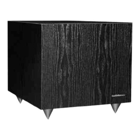
Induction Dynamics SW3 User manual

SW3
12” Subwoofer

Table of Contents
Introduction
General Information
Check Speaker and Parts
General Care of Your Subwoofer and Amplifier
Bass and Loudness Contour Controls
SW3 Location; Multiple Subs Location
Amplifier Location
Speaker Wire
Speaker Information
Subwoofer Design
Installing the SW3 With A2 Amplifier
Installing the SW3 With A3 Amplifier
SW3 Specifications
A2 Subwoofer Specifications
A3 Subwoofer Specifications
Warranty
Contacts
2
3
3
3
3
3
4
4
5
5
6
8
10
11
12
13
1
14

Audio Perfection Realized ™
2
Introduction
Congratulations on your selection of the Induction Dynamics™ SW3 12” closed-box
subwoofer. The SW3 is a powered subwoofer, with two amplification options:
Choosing the external A2 subwoofer amplifier allows greater placement flexibility; since the
amp will be mounted with other equipment, the subwoofer itself can be placed freestanding
or built into walls, ceilings or floors.
The A3 internal subwoofer amplifier is advantageous in that it saves space in the equipment
area. Like all amplifiers, the A3 will create heat, so an SW3 with A3 amplifier should NOT
be built into walls, etc.
Built to the highest standards of perfection, the SW3 makes an excellent addition to any home
theater, but to achieve the highest quality sound, we recommend using it in conjunction
with Induction Dynamics speakers. For a full catalog, contact Induction Dynamics at sales@
inductiondynamics.com or by calling toll free (866) 663-9770.
WARNINGS:
WARNING! - SHOCK HAZARD
WARNING! - DO NOT OPEN
NO USER-SERVICEABLE PARTS INSIDE
REFER SERVICING TO QUALIFIED PERSONNEL

3
General Information
Please read these instructions thoroughly before attempting to install and operate the SW3
subwoofer.
Check Speaker and Parts
Unpack and carefully check each loudspeaker. If you suspect damage from transit, report
the problem immediately to your dealer and/or delivery service.
If possible, save the shipping cartons for future use. Please ship the foam packing material
to: Induction Dynamics, 10661 René, Lenexa KS 66215.
General Care of Your Loudspeaker and Amplifier
Whenever changing speaker wires, interconnect wires, or power cords, always turn off all
equipment. To prevent fire or shock hazard, do not expose the amplifier to rain or excessive
moisture. To avoid electric shock, do not open the amplifier. There are no user-serviceable
parts inside.
Your subwoofer and amplifier come in a high quality finish that is both attractive and durable.
To clean, use a soft, damp cloth. If your drivers become dusty, dust them with a paintbrush
or a brush vacuum attachment. Do not use a strong or abrasive cleaner.
The grille is covered in acoustic cloth. To keep your grille clear of debris, we recommend
you use a lint roller (like you would use on clothes).
Bass and Loudness Contour Controls
Do not use bass or loudness contour controls. Induction Dynamics’ subwoofers produce
very low frequencies without these controls. Use of these controls will make the bass sound
“boomy”, obscure higher frequencies, and possibly cause damage due to excessive cone
excursion.
SW3 Location
The SW3 is normally freestanding within the listening environment, but may be built into
walls if used with the A2 external subwoofer amplifier.
Where possible, it is generally best to use two subwoofers, each located in a different area of
the room. In addition to improving efficiency and doubling the power handling, using two
subwoofers creates a more even distribution of the low frequencies by reducing peaks and
nulls. Two SW3s must be connected in series.

4Audio Perfection Realized™
Amplifier Location
The A2 amplifier is best located in an equipment rack or shelving with other audio and
video equipment. It is not recommended for placement behind walls or other limited access
locations, where service may be restricted.
The A3 amplifier is built in to the SW3. If you chose the A3 option, make sure to place your
SW3 in an open area with plenty of ventilation. Do NOT build in to walls or place the SW3
in a closed area.
Speaker Wire
Use approved wire designed for in-wall or exposed use, as appropriate for your installation.
For the SW3, we recommend using high-quality speaker wire that is 12 gauge or lower,
with easily visible polarity coding to make your connections. The following chart identifies
minimum gauge requirements for various lengths. See your local dealer or installation
contractor for more information.

5
Subwoofer
Information
Subwoofer Design
Non-realistic, “boomy” bass frequencies are so prevalent in the home theater world that
some listeners have never heard a well-tuned subwoofer. The “boom” occurs because every
subwoofer has a natural resonance peak—that is, every subwoofer will naturally produce
a narrow range of low frequencies at a higher volume than the rest. This “boom” drowns
out higher frequencies your subwoofer produces, resulting in diminished performance and
muddy, poor-quality bass.
Induction Dynamics® engineers its subwoofers with high-performance drivers and
specialized filter circuits to eliminate resonance peaks and produce a fuller sound expressing
all bass frequencies.
Most subwoofers do not attempt to reproduce ultra-low frequencies because of the distortion
created by excess excursion. Induction Dynamics eliminates this distortion with a patented
frequency-selective excursion limiter. The excursion limiter allows the subwoofer to produce
ultra-low frequency sound but prevents the driver from overexerting and causing distortion
that could ruin your listening experience; the limiter itself is transparent, operating only at
specific frequencies without audibly switching on and off.

6Audio Perfection Realized™
Installing the SW3
With A2 Amplifier
The A2 is designed to be used with audio/video pre-amplifiers and receivers that have their
own built-in low frequency crossover circuits. These circuits typically have a low pass rolloff
of 12dB/octave or 24 dB/octave. The best crossover frequency setting is usually 60 Hz (12
dB/octave low pass) or 70 Hz (24 db/octave low pass). Ultimately, the crossover frequency
setting is best determined by consulting your own ears.
Connecting the A2 to Your SW3
1. Turn off the power to each piece of equipment before making any connections.
2. Using high-quality interconnect cables with RCA type terminations, connect the
“SUBWOOFER OUT” on the audio/video preamplifier or receiver to “IN” on the A2. If using
a single subwoofer, proceed to step 3; if using two subwoofers, skip step 3 and proceed to
step 4.
3. Using high-quality speaker wire (consult the chart on page 4), connect the black binding
post on the A2 to the black binding post on the SW3 subwoofer and connect the red binding
post on the A2 to the red binding post on the SW3 subwoofer. Proceed to step 5.
4. If using a single A2 with two subwoofers, the subs must be connected in series. In this
configuration, the two 4-ohm loads will combine to create an 8-ohm load. Connect the red
binding post of the A2 amplifier to the red binding post on the first subwoofer, and the black
binding post on the A2 amplifier to the black binding post on the second subwoofer. Then
connect the black binding post on first subwoofer to the red binding post on the second
subwoofer. Three subwoofer connection methods are shown on the opposite page. Proceed
to step 5.
5. Connect the amplifier to a 120-volt, single phase, 60-Hz, grounded power supply
using the power cord provided. For best results, use a dedicated power circuit for your
amplification equipment.
6. Phase Check: Listen to the subwoofer(s) and higher frequency speakers together. Then,
reverse the speaker wires on the back of the subwoofer (black to red and red to black).
This reverse connection is 180ºout of phase with the normal connection. One of these
two arrangements will sound noticeably louder in the low-frequency range. The louder
arrangement is the proper phase alignment for your installation.

7
7. Volume Adjustment: The subwoofer volume level may be adjusted by using the control
in the menu of the audio/video preamplifier or receiver. The subwoofer volume level may
be measured using a sound level meter, a real time analyzer, or adjusted by ear. An easy
technique is to set the level just below where it starts to sound “boomy”.

8Audio Perfection Realized™
Installing the SW3
With A3 Amplifier
The A3 amplifier has a built-in adjustable low-pass crossover with a bypass switch on the
back panel. This allows the subwoofer to be used with audio/video pre-amplifiers and
receivers that have their own built-in low-frequency crossover circuits.
Connecting the A3 to Your Amplifier/Receiver
The SW3 has several connection options. Read through steps 1 - 4 and choose the applicable
method for your setup, then proceed to step 5.
1. Standard Subwoofer Connection - preamp or receiver with sub output
Using high-quality interconnect cables with RCA type terminations, connect the
SUBWOOFER OUT on the audio/video preamplifier or receiver to either the L or R LOW
LEVEL inputs on the back of the A3 amplifier. In this configuration you will use the built-in
crossover circuits in the audio/video preamplifier or receiver so the low-pass switch on the
A3 amp should be in the “out” position. This bypasses the crossover. Proceed to step 5.
2. Connecting Multiple Subwoofers - preamp or receiver with sub output
Using high-quality interconnect cables with RCA type terminations, connect the
SUBWOOFER OUT on the audio/video preamplifier or receiver through a Y-connector to
either the L or R LOW LEVEL inputs on the backs of both A3 amplifiers. In this configuration
you will use the built-in crossover circuits in the audio/video preamplifier or receiver so the
low-pass switch on the A3 amp should be in the “out” position. This bypasses the crossover.
Proceed to step 5.
3. Special Low-Level Stereo Connection - preamp or receiver without sub output
Using high-quality interconnect cables with RCA type terminations, connect the RIGHT and
LEFT PREAMP OUT on the audio/video preamplifier or receiver through two Y-connectors
to the corresponding L IN or R IN on the A3. Then, connect the free leg of the Y-connectors
to the L and R inputs on the audio/video receiver or amplifier used to power the higher
frequency range speakers. In this configuration you will use the low-pass crossover in the
A3 amplifier, so the low-pass switch on the A3 amp should be in the “in” position. Proceed
to step 5.

4. Special High-Level Stereo Connection - preamp or receiver without sub output
The high-level method is recommended for setups where the receiver is a long distance from
the main left and right speakers and subwoofer.
Connect the L and R speaker leads from the main amp directly to the high-level terminals
marked FROM AMPLIFIER on the A3 amp. Then connect a second pair of speaker leads
to your L and R main speakers. The high-level terminals are capable of connecting leads
terminated with either bare wire ends or “banana” plugs. If your leads have “banana” plugs
on them, the plastic decorative plugs may be removed from the high-level terminals on the
A3 amplifier. When using the high-level terminals, be sure to verify the positive leads are
connected to the red terminals and the negative leads are connected ot the black terminals
on all connections. In this configuration you will use the low-pass crossover in the A3
amplifier, so the low-pass switch on the A3 amp should be in the “in” position. Proceed to
step 5.
5. Connect the amplifier to a 120-volt, single phase, 60-Hz, grounded power supply
using the power cord provided. For best results, use a dedicated power circuit for your
amplification equipment.
6. If you used connection method 3 or 4, you will need to adjust the low pass. Initially, set
the low pass at the lowest frequency specified by the manufacturer for the main speakers.
For example, if the frequency response of your mains is specified as 55-20,000 Hz, set the
low pass at 55 Hz. Later, after setting volume level and checking phase, you can fine tune
the low pass setting.
7. Due to varying processor designs and possible phase switches, it is best to check the
phase of your SW3 for proper alignment. Your SW3 with built-in A3 amplifier has a phase
switch on the back panel. To test for proper phase, play some music that has some low-
frequency sound. Listen to the subwoofer and higher frequency speakers together. With
an assistant manning the phase switch, listen to the frequencies slightly above the lowest
frequencies (at crossover), asking the assistant to switch between the two positions. One
of these two positions will sound noticeably louder in the crossover frequency range. The
louder position is the proper phase alignment for your installation.
8. You can adjust the subwoofer level using the gain control on the back of the A3 amplifier.
The gain control is precisely stepped in 1/2 dB increments, allowing settings for various
applications to be easily repeated. For flexibility, a 3-position switch is provided which
allows the selection of additional gains of +10, 0, -10 dB; these gain controls are in addition
to the control in the menu of the audio/video preamplifier or receiver.
9

10 Audio Perfection Realized™
SW3 Specifications
Type: Powered subwoofer
Driver Control: High-saturation filter circuit to eliminate resonance peaks
Nominal Impedance: 4 Ohms (2.5 minimum)
Frequency Response: 20 - 150 Hz
Sensitivity (2.83 V @ 1M): 81 dB
SPL (1 W / 1 m): 78 dB
Power Handling: 500 W
Magnetic Shielding: No
Drivers: 12” laminated cone with rubber surround and 88-oz.
magnet
Binding Posts: Gold-plated; #4 AWG Max
Enclosure: Sealed
Optional Accessories: ST2.SW3 dual-post subwoofer stand

11
A2 Specifications
Type: Class AB Bipolar Subwoofer Amplifier
Driver Control: Patented non-distorting, frequeny-selective excursion
limiter
Frequency Response: 20 Hz - 20 kHz, +/- 0.25 dB
Harmonic Distortion: < 0.078% (@ 1 kHz, 1 Watt)
Voltage Gain (dB) S/N: 36 dB (internally switchable to 26 dB)
Damping Factor: 95 dBA
Input Impedance: 400 Ohms @ 60 Hz
Output Load: 2.5 K Ohms minimum
Power Output
(Continuous)
2.5 Ohms / 4 Ohms /
8 Ohms
700 Watts / 520 Watts / 300 Watts
Inputs: 1 RCA (RCA plus XLR optional)
Output Binding Posts: Gold Plated; #10 AWG max, or Banana Plugs
Power Requirements: 120 V AC, 6A slow-burn fuse
Auto On/Off Auto power down if no signal for 20 minutes (turn-on
sensitivity 2 mV)

12 Audio Perfection Realized™
A3 Specifications
Type: Class AB Bipolar Subwoofer Amplifier with 2-stage power
supply
Driver Control: Patented non-distorting, frequeny-selective excursion
limiter
Frequency Response: 20 Hz - 20 kHz, +/- 0.25 dB
Harmonic Distortion: < 0.05% (@ 1 kHz, 1 Watt)
Voltage Gain (dB) S/N: 38 dB (internally switchable to 28 dB or 48 dB plus rotary
gain control +/- 9 dB in 1/2 dB steps)
Damping Factor: 95 dBA
Input Impedance: 300 Ohms @ 60 Hz
Output Load: 2.5 K Ohms minimum
Power Output
(Continuous)
2.5 Ohms / 4 Ohms /
8 Ohms
640 Watts / 500 Watts / 360 Watts
Inputs: L & R RCA Low and high levels (RCA plus XLR optional
without high levels)
Output Binding Posts: N/A
Power Requirements: 120/240 V AC; 50/60 Hz; 6A slow-burn fuse
Auto On/Off Auto power down if no signal for 20 minutes (turn-on
sensitivity 2 mV)
Level Controls: 120/240 V AC; 50/60 Hz; 6A slow-burn fuse

13
Warranty
Phone: 855.663.5600
Fax: 913.663.3200
Induction Dynamics, Inc. warrants the SW3 subwoofer, A2 amplier, and/or A3 amplier
against defects in materials and workmanship for a period of seven years from the date of
original retail purchase. Induction Dynamics, Inc. will repair or replace any SW3 sub-
woofer, A2 amplier, and/or A3 amplier that does not meet this warranty.
This warranty may be registered by mailing a copy of the retail sales receipt to Induction
Dynamics, Inc. at the address below. Please write the serial number along with the name
and address of the retailer from whom you purchased the speaker(s) and/or amplier(s).
This may be done at the time of purchase or before requesting repair service under this
warranty.
To obtain repair service, call or write to Induction Dynamics, Inc. at the phone number or
address below. You will be given a return authorization number. Please mark this number
clearly on the outside of the package(s) for identication. Packages that are not marked
with a return authorization number on the outside may not be accepted by Induction
Dynamics, Inc. Please pack each SW3 subwoofer, A2 amplier, and/or A3 amplier in a
substantial shipping container with plenty of protective foam. If possible, use the original
shipping container and packing material. For repairs covered by and performed under
this warranty, Induction Dynamics, Inc. will pay for the return shipping charges. This
warranty covers defects in materials and workmanship, and does not cover damage or
failure resulting from accident, misuse, or shipment. The warranty is void if the SW3
subwoofer, A2 amplier, and/or A3 amplier is serviced or altered by anyone other than
Induction Dynamics, Inc. the sole remedy for breach of this warranty shall be repair or
replacement.
Limits and Exclusions: There are no warranties except as mentioned above. Neither
Induction Dynamics, Inc. nor anyone else who has been involved in the creation, pro-
duction, or sale of this product shall be liable for any direct, indirect, consequential or
accidental damages arising out of the use or inability to use this product, or arising out
of breach of this warranty. Induction Dynamics, Inc. makes no other warranties, express
or implied, including without limitation warranties of merchantability or tness for a
particular purpose. There are no warranties that extend beyond the description on the
face hereof.
Induction Dynamics
Customer Service Department
8005 W. 110th St., Suite 208
Overland Park, KS 66210
USA

14
Contacts
If you have any questions, contact Induction Dynamics by phone at 855-663-5600, 8:00
write to:
Manufacturer Information
Retailer Information
Retailer name (company or individual):
Address:
City:
State:
Zip or Postal code:
Phone:
Email:
Date of purchase:
Serial number:
Induction Dynamics
Customer Service Department
8005 W. 110th St., Suite 208
Overland Park, KS 66210
USA
Note: Please do not ship your loudspeaker for service without obatining prior approval
and return authorization number. See warranty for further information.
To help simplify your record keeping, please ll out the following information about the
retailer you bought your Induction Dynamics products from. Additionally, you may staple,
tape, or glue a copy of your receipt to the next page.

15
To simplify your record keeping,
please glue, staple, or tape your receipt
to this page.

16 Audio Perfection Realized™

™
8005 W. 110th Street, Suite 208
Overland Park, KS 66210
Tel: (855) 663-5600
Fax: (913) 663-3200
www.inductiondynamics.com
© Induction Dynamics®, August 2013
This manual suits for next models
1
Table of contents
Other Induction Dynamics Subwoofer manuals

