Industrial Scientific MX4 iQuad User manual

Part Number: 17140724-1
Revision: 2.0
Release Date: April 26, 2009

Operation Guide
Table of Contents
WARNINGS AND CAUTIONARY STATEMENTS----------------------------4
INTRODUCTION----------------------------------------------------------------------7
HARDWARE OVERVIEW ----------------------------------------------------------8
UNPACKING THE INSTRUMENT -----------------------------------------------9
DISPLAY OVERVIEW ---------------------------------------------------------------9
TURNING THE MX4 ON AND OFF ---------------------------------------------10
GENERAL OPERATION -----------------------------------------------------------11
DAYS SINCE CALIBRATION SCREEN------------------------------------------------12
BUMP TEST SCREEN (IF ENABLED)--------------------------------------------------12
ZERO SCREEN (IF ENABLED)---------------------------------------------------------13
PEAK READINGS SCREEN ------------------------------------------------------------13
TIME WEIGHTED AVERAGE (TWA) READINGS SCREEN -------------------------14
SHORT TERM EXPOSURE LIMIT (STEL) READINGS SCREEN---------------------14
CHARGING SCREEN (FROM ON STATUS) ------------------------------------------15
CHARGING SCREEN (FROM OFF STATUS) -----------------------------------------15
IRDA COMMUNICATIONS SCREEN--------------------------------------------------15
MISSING SENSOR/NO SENSORS INSTALLED SCREEN -----------------------------16
LOW BATTERY LIFE SCREEN --------------------------------------------------------16
OVERRANGE ALARM SCREEN -------------------------------------------------------16
CAL DUE ALARM SCREEN -----------------------------------------------------------17
LOW ALARM SCREEN ----------------------------------------------------------------17
HIGH ALARM SCREEN----------------------------------------------------------------17
TWA ALARM SCREEN ---------------------------------------------------------------17
STEL ALARM SCREEN ---------------------------------------------------------------18
CALIBRATION -----------------------------------------------------------------------19
CONFIGURATION MODE---------------------------------------------------------22
INTRODUCTION------------------------------------------------------------------------22
SECURITY CODE ----------------------------------------------------------------------22
COMBUSTIBLE GAS OPERATING MODE SCREEN ----------------------------------23
ENTER ZERO SCREEN-----------------------------------------------------------------24
CALIBRATION MODE SCREEN -------------------------------------------------------24
LOW ALARM SET POINT -------------------------------------------------------------24
HIGH ALARM SET POINT-------------------------------------------------------------25

Operation Guide
Rev 2.0 (p/n: 17140724) INDUSTRIAL SCIENTIFIC 3
TWA ALARM SET POINT (OPTIONAL) ---------------------------------------------25
TWA TIME BASE SCREEN (OPTIONAL) --------------------------------------------26
STEL ALARM SET POINT (OPTIONAL) ---------------------------------------------26
CAL GAS SETPOINT SCREEN---------------------------------------------------------27
CLOCK SETTING SCREEN ------------------------------------------------------------27
DATE SETTING SCREEN --------------------------------------------------------------28
DISPLAY MODE SETTING SCREEN --------------------------------------------------28
CONFIDENCE INDICATOR SCREEN --------------------------------------------------29
FIELD BUMP TEST OPTION-----------------------------------------------------------29
BUMP OVERDUE ALARM ENABLE --------------------------------------------------29
BUMP TEST INTERVAL SCREEN -----------------------------------------------------30
BUMP TEST THESHOLD SREEN ------------------------------------------------------30
BUMP TEST TIMEOUT SCREEN ------------------------------------------------------31
ALARM LATCH SET SCREEN---------------------------------------------------------31
ZERO ENABLE SCREEN---------------------------------------------------------------32
CAL ENABLE SCREEN ----------------------------------------------------------------32
CAL DUE ALARM OPTION SCREEN -------------------------------------------------32
CAL DUE SETPOINT SCREEN---------------------------------------------------------33
CODE SET SCREEN--------------------------------------------------------------------33
DATA LOGGING -----------------------------------------------------------------------34
MAINTENANCE----------------------------------------------------------------------35
CLEANING -----------------------------------------------------------------------------35
CHARGING THE BATTERIES----------------------------------------------------------35
BATTERY REPLACEMENT ------------------------------------------------------------35
SENSOR AND FILTER REPLACEMENT -----------------------------------------------36
SPECIFICATIONS -------------------------------------------------------------------37
PHYSICAL SPECIFICATIONS ----------------------------------------------------------37
SENSOR SPECIFICATIONS-------------------------------------------------------------37
ENVIRONMENTAL SPECIFICATIONS -------------------------------------------------38
BATTERY SPECIFICATIONS-----------------------------------------------------------38
REPLACEMENT PARTS -----------------------------------------------------------39
EXPLODED VIEW DIAGRAM----------------------------------------------------40
WARRANTY---------------------------------------------------------------------------41
LIMITATION OF LIABILITY-----------------------------------------------------------41

Operation Guide
Warnings and Cautionary Statements
IMPORTANT: Failure to perform certain procedures or note certain
conditions may impair the performance of this product. For maximum
safety and optimal performance, please read and follow the procedures
and conditions listed below.
IMPORTANT: Read and understand this manual before
operating.
AVERTISSEMENT: Lire attentivement les instructions avant de
mettre en marche.
WARNING: SERVICING THE UNIT, REPLACING THE
RECHARGEABLE BATTERY PACK, OR CHANGING THE
ALKALINE BATTERIES MUST ONLY BE DONE IN AN AREA
KNOWN TO BE NONHAZARDOUS.
WARNING: INSERT THE ALKALINE BATTERIES WITH THE
CORRECT POSITIVE “+” AND NEGATIVE “-“ ORIENTATION.
FAILURE TO FOLLOW PROPER BATTERY ORIENTATION
WILL RESULT IN DAMAGE TO THE INSTRUMENT.
WARNING: THE MX4 IS ONLY APPROVED FOR USE WITH
AAA BATTERY TYPES ENERGIZER EN92 AND DURACELL
MN2400. DO NOT MIX BATTERY TYPES.
A functional bump test of the instrument should be performed
before each day’s use. If the instrument does not pass the bump
test, a full instrument calibration should be performed prior to
use.
The MX4 is CSA certified according to the Canadian Electrical
Code for use in Class I, Division 1 and Class I, Zone 1
Hazardous Locations within an ambient temperature range of
Tamb: -20°C to +50°C. CSA has assessed only the %LEL
combustible gas detection portion of this instrument for
performance according to CSA Standard C22.2 No. 152,
applicable only when the instrument is used in the diffusion
mode and has been calibrated to 50% LEL CH4.
Oxygen deficient atmospheres may cause combustible gas
readings to be lower than actual concentrations.
Oxygen enriched atmospheres may cause combustible gas
readings to be higher than actual concentrations.

Operation Guide
Rev 2.0 (p/n: 17140724) INDUSTRIAL SCIENTIFIC 5
Verify the calibration of the combustible gas sensor after any
incident where the combustible gas content has caused the
instrument to display an over-range condition.
Silicone compound vapors or other known contaminants may
affect the combustible gas sensor and cause readings of
combustible gas to be lower than actual gas concentrations. If
the instrument has been used in an area where silicone vapors
were present, always calibrate the instrument before next use to
ensure accurate measurements.
Sensor openings and water barriers must be kept clean.
Obstruction of the sensor openings and/or contamination of the
water barriers may cause readings to be lower than actual gas
concentrations.
Sudden changes in atmospheric pressure may cause temporary
fluctuations in the oxygen reading.
Charge battery, service unit, and use its communication port
only in non-hazardous locations. Not for use in oxygen-enriched
atmospheres.
WARNING: Substitution of components may impair intrinsic
safety and may cause an unsafe condition.
AVERTISSEMENT: La substitution de composants peut
compomettre la securite intrinseque.
CAUTION: For safety reasons, this equipment must be operated
and serviced by qualified personnel only. Read and understand
the instruction manual completely before operating or servicing.
ATTENTION: Pour des raisons de sécurité, cet équipment doit
étre utilesé entretenu et réparé uniquement par un personnel
qualifié. Étudier le manuel d'instructions en entier avant d'utiliser,
d'entretenir ou de réparer l'équipement.
CAUTION: High off-scale readings may indicate explosive
concentration.
ATTENTION: Des lectrures supérieures a l'échelle peuvent
indiquer des concentrations explosives.

Operation Guide
6 INDUSTRIAL SCIENTIFIC Rev 2.0 (p/n: 17140724)
CAUTION: Any rapid up-scale reading followed by a declining or
erratic reading may indicate a gas concentration beyond the
upper scale limit which may be hazardous.
CAUTION: CSA C22.2 No. 152 requires before each day’s
usage, sensitivity must be tested on a known concentration of
pentane or methane equivalent to 25% or 50% of full scale
concentration. Accuracy must be within -0% to +20% of actual
concentration. Accuracy may be corrected by referring to the
zero/calibration section of the instruction manual.
The model MX4 complies with relevant provisions of European
ATEX directive 94/9/EC and EMC directive 89/336/EEC,
amended by directives 92/31/EEC and 93/68/EEC.
The EC type examination certificate is DEMKO 09 ATEX
0854530 ; with marking code Ex ia d I/IIC T4; for equipment
group and category II 2G and I M2.
The MX4 iQuad Multi-Gas Monitor is constructed with reference
to published standards of directive 72/23/EEC, to eliminate
electrical risks and fulfill 1.2.7 of ANNEX II of directive 94/9/EC.
Contact your service representative immediately if you suspect
that the MX4 is working abnormally.
Specifications subject to change without notice.

Operation Guide
Rev 2.0 (p/n: 17140724) INDUSTRIAL SCIENTIFIC 7
Introduction
The MX4 is a light-weight, portable gas monitor capable of continuously
and simultaneously monitoring 4 gases:
Oxygen (O2)
Combustible (LEL and CH4)
Two interchangeable toxics (CO, H2S, NO2)
The sensors are easily replaced. Gas readings from the installed sensors
are displayed on a custom graphic LCD. Peak readings are also available
for each sensor, and can be cleared by the user.
The instrument provides alarms for the following conditions:
low limit (user adjustable)
high limit (user adjustable)
STEL (user adjustable)
TWA (user adjustable)
overdue for calibration (user selectable).
Overdue for bump test (user selectable)
When alarm conditions are exceeded, the MX4 has an audible, visual and
standard vibrating alarm to alert the user.
The MX4 is compatible with the MX•Cal™ calibration station, the DS2
Docking Station™, and its own cradle-style charger. It communicates to
the Charger/Datalink via infrared communications (IrDA). MX4 is also
compatible with Industrial Scientific’s automated and comprehensive gas
monitor management solution, iNet™.
The MX4 performs continuous data logging at 10 second intervals and
can hold approximately three month’s of data for the four-sensor
configuration. Readings are time-stamped and are stored in a first-in-first-
out (FIFO) queue that is overwritten when full. In addition to data logging,
the MX4 has an event log that records the last 15 alarm events.

Operation Guide
8 INDUSTRIAL SCIENTIFIC Rev 2.0 (p/n: 17140724)
Enter
Button
On/Off/Mode
Button
Audible
Alarm Port
Charging
Contacts IrDA Interface
Instrument
Display
Visual Alarm
Indcators
Sensor
Ports
Hardware Overview

Operation Guide
Rev 2.0 (p/n: 17140724) INDUSTRIAL SCIENTIFIC 9
Unpacking the Instrument
The shipping box should contain the following items. Account for each
item before discarding the box.
Quantity Description
1 MX4 iQuad Multi-Gas Monitor
1 Manual
1 Battery Pack (installed as ordered)
1 Cradle-style Charger with Power Cord
1 Calibration Cup and Tubing
After unpacking, if any listed item is missing, contact either your local
distributor of Industrial Scientific products or call Industrial Scientific
Corporation at 1-800-DETECTS (338-3287) in the United States and
Canada, or 412-788-4353.
Display Overview
LCD Display Panel Overview

Operation Guide
10 INDUSTRIAL SCIENTIFIC Rev 2.0 (p/n: 17140724)
Turning the MX4 ON and OFF
To turn on the MX4, press and hold the On/Off/Mode button ( ) until the
unit emits a single beep (approximately 3 seconds). All icons and
segments on the LCD display as shown in the graphic above. Next, the
software version is displayed. After this, the instrument performs a 20
second countdown, during which the user has the option to enter the
configuration mode (by pressing and holding both the On/Off/Mode ( )
and Enter ( ) buttons simultaneously). If this configuration mode option is
bypassed, the MX4 enters the normal operating mode and displays the
normal monitoring screen. Sequential presses of the On/Off/Mode button
will cycle the user through the Days Since Calibration Screen, Zero
Screen (if enabled), Peak Readings Screen, Time Weighted Average
(TWA) Screen (if toxic sensors are installed) and the Short Term
Exposure Limit (STEL) Screen (if toxic sensors are installed). Another
press of the On/Off/Mode button returns the user to the normal monitoring
screen. Each screen is explained individually in the sections that follow.
To turn off the MX4, press and hold the
On/Off/Mode button for 5 seconds. During
the shutdown process, the displayed value
will change from “5” to “1” and the MX4 will
beep five times.
NOTE: Any button press activates the backlight for a period of 30 seconds.
Operation Guide
Rev 2.0 (p/n: 17140724) INDUSTRIAL SCIENTIFIC 11
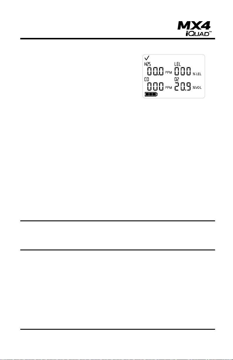
General Operation
The normal monitoring screen in numeric
mode contains the abbreviated names and
concentrations of all 4 gases. In text mode,
the sensor names are displayed instead of
the numerical values. The gasses are
continuously monitored and the readings
updated on the LCD. If any of the gas
concentrations exceed the low or high
alarm limits (as well as STEL/TWA), the
MX4 will go into alarm. When in alarm, the
audible and visual alarms will beep and
flash at set frequencies, and the vibrating
alarm will be pulsed.
When the gas concentrations return to normal values (for example, drop
out of the range that will cause an alarm condition), and the alarm latching
feature is not set, the MX4 will go back to the normal monitoring screen.
The normal monitoring screen may appear differently based on which
sensors are installed and which display mode is selected.
A battery life indicator is displayed in the lower left corner of the LCD. As
battery life decreases, the shaded area of the battery icon decreases.
Pressing the On/Off/Mode button from the Normal Monitoring screen
displays the Days Since Calibration screen.
NOTE: In an over-range condition, the display will show a blinking “OR”,
in a negative over-range condition “-OR” will be shown. Any over-range
values in the event log or peaks will be truncated at the measurement
range of the sensor.

Operation Guide
12 INDUSTRIAL SCIENTIFIC Rev 2.0 (p/n: 17140724)
Days Since Calibration Screen
The Days Since Calibration screen displays
the calibration bottle icon, the calendar
icon, the names of the four installed
sensors, and the corresponding number of
days since each sensor was last calibrated.
Pressing the On/Off/Mode button from the Days Since Calibration screen
displays the Bump Test screen (if enabled in the configuration mode).
Bump Test Screen (if enabled)
The bump test screen allows the user to
initiate and perform a manual bump test of
the instrument using calibration gas. (This
screen will only be seen if the bump test
option is enabled in the configuration
mode.)
After initiating the bump test by pressing the Enter button at this screen,
the user will apply the calibration gas to the instrument as described under
Calibration. If the sensor responds to the percentage of the calibration gas
value programmed in the configuration mode within the timeout specified
in the configuration mode, the instrument will pass the bump test. If the
sensor does not respond to the programmed percentage of the gas
concentration within the timeout period, the instrument will fail the bump
test and require calibration. A failed sensor will show “b F” on the display
instead of the gas reading for that particular sensor. If the bump overdue
alarm is enabled in the configuration mode, “b” will be shown for the gas
reading and the sensor name will flash when the bump test is overdue.
This screen will appear when the instrument is turned on and remain until
a bump test of the instrument is completed successfully.
Pressing the On/Off/Mode button from the Bump Test screen displays the
Zero screen (if enabled in the configuration mode).
Operation Guide
Rev 2.0 (p/n: 17140724) INDUSTRIAL SCIENTIFIC 13
IMPORTANT: A function or “bump” test, using a known concentration of
calibration gas, should be performed periodically based on instrument use,
exposure to gas, and environmental conditions. The frequency is best
determined by company policy or local regulatory agencies. If an
instrument fails a function or “bump” test, or, if it is dropped, submerged,
or appears damaged, a full calibration is recommended. The safest
approach is to perform a function or “bump” test prior to each day’s use.
Industrial Scientific is not responsible for establishing customer safety
practices and policies.
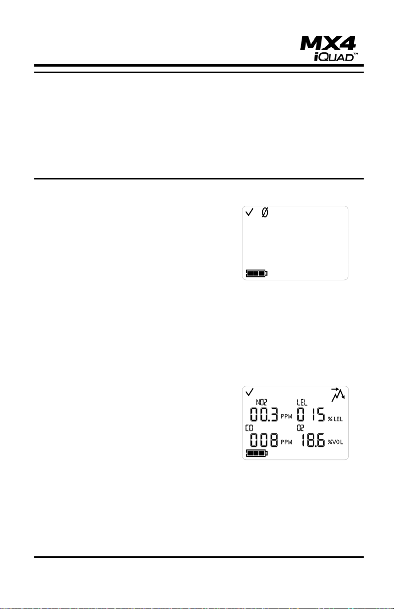
Zero Screen (if enabled)
If zeroing is enabled (via the Zero Enable
screen in the Configuration section), then
the Zero screen is displayed. From this
screen the user initiates the zeroing process
of the sensors by pressing the Enter button.
The zeroing process should only be initiated
when the instrument is in clean ambient air.
If clean air is not available, a cylinder of
zero grade air should be used. (Refer to the
Zeroing and Calibration processes later in
this manual).
Pressing the On/Off/Mode button from the Zero screen displays the Peak
Readings screen.
Peak Readings Screen
The Peak Readings screen displays the
peak icon, the names of the four installed
sensors, and the corresponding peak
values for each since the last time the peak
value(s) were cleared.
Pressing the Enter button resets all of the
peak values to the current reading.
If one or more toxic gas sensors are installed, then pressing the
On/Off/Mode button from the Peak Readings screen displays the TWA
Readings screen.
If no toxic gas sensors are installed, then pressing the On/Off/Mode
button from the Peak Readings screen returns the user to the Normal
Monitoring screen.

Operation Guide
14 INDUSTRIAL SCIENTIFIC Rev 2.0 (p/n: 17140724)
Time Weighted Average (TWA) Readings Screen
The TWA Readings screen is only
displayed if one or more toxic gas sensors
are installed.
The TWA Readings screen displays the
TWA icon, the names of the installed toxic
sensor(s), and the corresponding time
weighted average gas concentration for
each.
Pressing the Enter button while on this screen resets the TWA and STEL
values. The time base for TWA calculation may be set in the configuration
mode. The default time base is set for 8 hours.
Pressing the On/Off/Mode button from the TWA Readings screen displays
the STEL Readings screen.
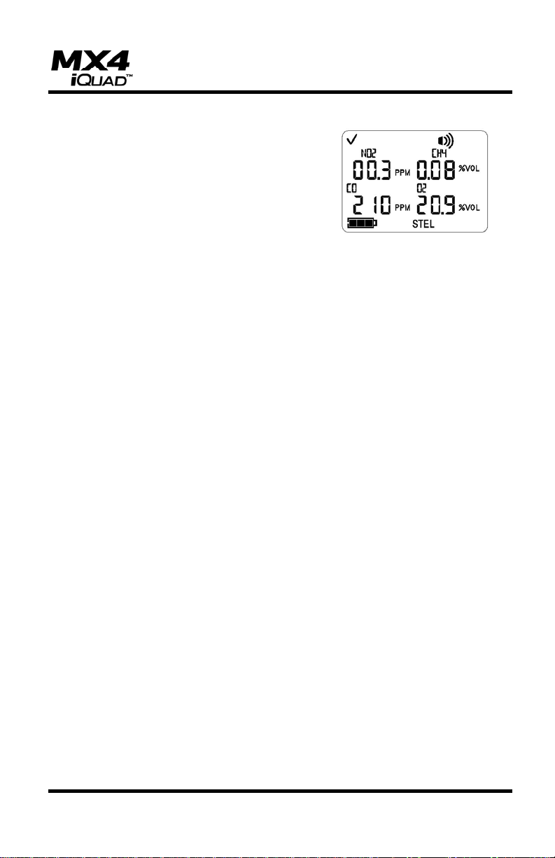
Short Term Exposure Limit (STEL) Readings Screen
The STEL Readings screen is only
displayed if one or more toxic gas sensors
are installed.
The STEL Readings screen displays the
STEL icon, the names of the installed toxic
sensor(s), and the corresponding short-term
exposure limit for each.
The STEL (Short Term Exposure Limit) for the toxic sensors is reset every
time the unit is powered down. In addition, pressing the Enter button while
on this screen resets the STEL values, but not the TWA values. The STEL
readings are calculated as a running average of readings over the last 15
minutes.
Pressing the On/Off/Mode button from the STEL Readings returns the
display to the Normal Monitoring screen.

Operation Guide
Rev 2.0 (p/n: 17140724) INDUSTRIAL SCIENTIFIC 15
While in the normal operating mode, the MX4 display will vary depending
on current monitoring conditions. Variations of the display indicating the
charging, battery, calibration, sensor, communication and alarm status are
shown below.
Charging Screen (From ON Status)
When the MX4 is turned on and the Normal
Monitoring screen is displayed, docking the
instrument to charge it will cause the
instrument to turn off, and move to the
normal charging state. The battery icon will
cycle from empty to full to empty to indicate
that charging is taking place. The names of
any installed sensors are also shown. (The
battery indicator will show full when the
instrument battery is fully charged.) If the
unit is using an alkaline battery, the battery
icon will reflect the amount of battery life
left.
Charging Screen (From OFF Status)
When the MX4 is turned off, and then
docked, the battery life icon will be
displayed and will cycle from empty to full to
empty if the unit is being recharged. The
names of any installed sensors are also
shown. If the unit is using an alkaline
battery, the battery icon will reflect the
amount of battery life left.
IrDA Communications Screen
During IrDA communications, the IrDA
communications icon is displayed. This
happens only when the instrument is
docked.

Operation Guide
16 INDUSTRIAL SCIENTIFIC Rev 2.0 (p/n: 17140724)
Missing Sensor/No Sensors Installed Screen
If a sensor is not detected or is missing from
the instrument, the corresponding sensor
position on the display will be blank. If no
sensors are installed in the instrument the
display will be blank as shown and the
warning icon will flash.
Low Battery Life Screen
When battery power is nearly exhausted,
the battery icon will begin to flash. It will
continue to flash until the unit shuts down
due to insufficient power.
Over Range Alarm Screen
An over range condition occurs when the
gas concentration value read by the sensor
is above its specified measuring range.
During an over range condition, the “Or”
(Over Range) icon flashes in place of the
numerical value for the sensor that is in
over range.
For toxic sensors and/or the oxygen sensor, the over range alarm will
normally reset itself when the gas concentration returns to a level within
the sensor measuring range. However, if the LEL sensor reaches an over
range condition, the alarm will latch and the instrument must be turned off
and then on again to clear the over range condition.
The instrument should always be recalibrated after any over range
condition occurs.

Operation Guide
Rev 2.0 (p/n: 17140724) INDUSTRIAL SCIENTIFIC 17
Cal Due Alarm Screen
When a sensor calibration is due, the gas
bottle icon and the associated sensor icon
flash. In addition, the MX4 beeps every five
seconds to alert the user that calibration is
past due.
Low Alarm Screen
When a low alarm condition occurs (based
on the low alarm limit settings in the
configuration menus), the alarm icon and
the down arrow (low limit) icon are
displayed. Depending on the display mode
that is selected, either the gas reading value
will flash or the alarming gas type text will
flash (Text display mode).
High Alarm Screen
When a high alarm condition occurs (based
on the high alarm limit settings in the
configuration menus), the alarm icon and
the up arrow (high limit) icon are displayed.
Depending on the display mode that is
selected, either the gas reading value will
flash or the alarming gas type text will flash
(Text display mode).
TWA Alarm Screen
When a TWA alarm condition occurs (based
on the TWA alarm limit settings in the
configuration menus), the alarm icon and
the TWA icon are displayed. Depending on
the display mode that is selected, either the
gas reading value will flash or the alarming
gas type text will flash (Text display mode).
Operation Guide
18 INDUSTRIAL SCIENTIFIC Rev 2.0 (p/n: 17140724)
STEL Alarm Screen
When a STEL alarm condition occurs
(based on the STEL alarm limit settings in
the configuration menus), the alarm icon
and the STEL icon are displayed.
Depending on the display mode that is
selected, either the gas reading value will
flash or the alarming gas type text will flash.

Operation Guide
Rev 2.0 (p/n: 17140724) INDUSTRIAL SCIENTIFIC 19
Calibration
IMPORTANT: Industrial Scientific Corporation recommends that a
functional (“bump”) test be performed on every instrument prior to each
day’s use. A functional test is defined as a brief exposure of the monitor to
a concentration of gas(es) in excess of the lowest alarm set-point for each
sensor for the purpose of verifying sensor and alarm operation and is not
intended to be a measure of the accuracy of the instrument. If an
instrument fails to operate properly following any functional "bump" test,
full instrument calibration should be performed prior to use. If conditions
do not permit daily testing, bump tests may be done less frequently based
on instrument use, exposure to gas, and environmental conditions. The
frequency of testing is best determined by company policy or local
regulatory agencies.
Industrial Scientific further recommends that full instrument calibration be
performed using a certified concentration(s) of Industrial Scientific
calibration gas(es) monthly to ensure accuracy.
NOTE: CSA International requires the %LEL sensitivity to be tested
before each use. Any inaccuracy may be adjusted by calibration to 50%
LEL Methane.
NOTE: If the option to zero or calibrate in field is not enabled, the user will
not be able to calibrate the instrument in the field.
NOTE: If a security code is set, the user will not be able to enter the
configuration screens in the field. Please refer to Security Code Setting
section for more information.
The MX4 may be calibrated in the normal operating mode if field
calibration is enabled or in the configuration mode if field calibration is
disabled. Calibration is first initiated by advancing to the Zero screen if
calibration is to be performed in the normal operating mode or entering
the Configuration mode and then initiating the zero process. The MX4 has
two calibration options that may be selected in the Configuration mode.
The first is the Quick-Cal option in which all sensors will be calibrated
simultaneously using the appropriate blended cylinder of calibration gas.
The second option is the Standard-Cal option where sensors may be
calibrated individually using either blended or individual calibration gases.

Operation Guide
20 INDUSTRIAL SCIENTIFIC Rev 2.0 (p/n: 17140724)
The zeroing process is initiated by pressing
the Enter button when this zero screen is
being displayed. The zeroing process
should only be initiated when the instrument
is in clean ambient air. If clean air is not
available, a cylinder of zero grade air should
be used. During the zeroing process, the
toxic and combustible gas sensors are
zeroed and the oxygen sensor is calibrated
to ambient air.
When the zeroing process is completed,
calibration can be initiated by pressing the
On/Off/Mode button. The instrument display
will flash the calibration gas concentration
for the first sensor to be calibrated. The
calibration cup should be attached to the
instrument and the calibration gas applied
at a flow rate of 0.5 liters per minute.
The instrument will recognize the presence of calibration gas and begin
the calibration process. When the sensor has completed calibration, the
instrument will emit a short beep and the display will step to the next
sensor to be calibrated. If the Standard-Cal option is enabled, a sensor
may be skipped by pressing the On/Off/Mode button. If the oxygen sensor
calibration gas value is set to 20.9%, the oxygen sensor will not be
available for calibration in this mode because it was calibrated during the
zeroing process and the oxygen sensor display position will be blank.
When the calibration is complete, the
instrument will display the Pass/Fail status
of the calibration and the full span value for
each sensor. The full span value provides
an indication of the sensors operation
condition.
A full span value greater than 70% of the applied calibration gas value
indicates a healthy sensor. A full span value between 50% and 70% of the
applied gas concentration are considered to have marginal sensitivity and
limited life remaining. Sensors will fail calibration if the full span value is
less than 50% of the applied calibration gas concentration. If a sensor fails
calibration, the display reading for that sensor will be replaced by the letter
Table of contents
Other Industrial Scientific Monitor manuals


 manual")


