Industrial Scientific M40 User manual
9788
-0171
N
/
P
4 veR
0005-4070
det
n
i
r
P
eg
nah
C o
t t
cej
b
uS
s
no
ita
c
i
fi
c
ep
S
0051-17051 AP,
e
la
d
ka
O,
daoR
e
la
d
kaO 1001
ST
CETED
-008
-1
e
er
F
l
loT
• 35
34-887
)214(
3534-887
-888
-1 .t
p
eD
e
c
ivr
e
S • 3
538-887
-214 X
AF
no
i
tcurtsnI
la
u
naM
.
DEE
TN
A
R
AUG
ROTINOM SAG-ITLUM

OUR MISSION
Design - Manufacture - Sell:
Highest quality products
for the preservation of
life and property.
Provide:
Best customer service
available.

Dear Valued Customer,
Thank you for buying and using Industrial Scientific’s
M40 Multi-Gas Monitor.
Your M40 can be relied upon for dependable service, day
after day. It has been designed, manufactured, tested and
proven under the most scrutinizing conditions possible.
With the minimal care and maintenance described in this
Instruction Manual, it will provide you with years of
reliable monitoring.
I am most concerned that you be pleased with the
performance of your M40 in the months and years ahead.
I urge you to call us with any questions or comments you
may have. Often times a phone call and a question can
save you hours of frustration. Please never hesitate to
contact me at 1-800-DETECTS (338-3287).
All of us at Industrial Scientific appreciate the opportunity
to serve you.
Sincerely,
Kent D. McElhattan
President & CEO
Industrial Scientific Corporation

3
W
ARNINGS AND
C
AUTIONARY
S
TATEMENTS
Failure to perform certain procedures or note certain conditions
may impair the performance of the instrument. For maximum
safety and performance, please read and follow the procedures
and conditions outlined below.
Oxygen deficient atmospheres may cause combustible gas
readings to be lower than actual concentrations.
Oxygen enriched atmospheres may cause combustible gas
readings to be higher than actual concentrations.
Verify the calibration of the combustible gas sensor after any
incident where the combustible gas content has caused the
instrument to display an OVER-RANGE condition.
Silicone compound vapors or other known contaminants may
affect the combustible gas sensor and cause readings of combustible
gas to be lower than actual gas concentrations. If the instrument has
been used in an area where silicone vapors were present, always
calibrate the instrument before next use to ensure accurate
measurements.
Sensor openings and water barriers must be kept clean.
Obstruction of the sensor openings and/or contamination of the water
barriers may cause readings to be lower than actual gas
concentrations.
Sudden changes in atmospheric pressure may cause temporary
fluctuations in the oxygen reading.
Charge battery, service unit, and use its communication port only
in non-hazardous locations. Not for use in oxygen enriched
atmospheres.
WARNING: SUBSTITUTION OF COMPONENTS MAY IMPAIR
INTRINSIC SAFETY AND MAY CAUSE AN UNSAFE CONDITION.
AVERTISSEMENT: LA SUBSTITUTION DE COMPOSANTS PEUT
COMPOMETTRE LA SECURITE INTINSEQUE!
CAUTION: FOR SAFETY REASONS, THIS EQUIPMENT MUST BE
OPERATED AND SERVICED BY QUALIFIED PERSONNEL ONLY. READ
AND UNDERSTAND THE INSTRUCTION MANUAL COMPLETELY
BEFORE OPERATING OR SERVICING.
ATTENTION: POUR DES RAISONS DE SÉCURITÉ, CET ÉQUIPMENT
DOIT ÉTRE UTILESÉ ENTRETENU ET RÉPARÉ UNIQUEMENT PAR UN
PERSONNEL QUALIFIÉ. ÉTUDIER LE MANUEL D'INSTRUCTIONS EN
ENTIER AVANT D'UTILISER, D'ENTRETENIR OU DE RÉPARER
L'ÉQUIPEMENT.
!
!
!
!
!
!
!
!
!
2
WARNINGS AND CAUTIONARY STATEMENTS.....................................3
UNPACKING THE INSTRUMENT ........................................................5
VIEW OF INSTRUMENT ....................................................................6
INTRODUCTION................................................................................7
INSTRUMENT OPERATION.................................................................7
M40 Gas Reading Mode......................................................7
Operating Modes .................................................................8
Zero/Calibration Mode........................................................9
Display Peaks Mode............................................................9
View TWA Mode...............................................................10
View STEL Mode..............................................................10
CONFIGURATION MODE.................................................................10
Low Alarm Set Points........................................................11
High Alarm Set Points.......................................................11
TWA Alarm Set Points ......................................................12
STEL Alarm Set Points......................................................13
Clock Setting......................................................................13
Calendar Setting.................................................................14
Security Code Setting........................................................14
LEL Setting........................................................................15
Protected Zero/Cal Setting.................................................15
ZERO/CALIBRATION.......................................................................16
DATA LOGGING .............................................................................17
LEL OVER RANGE........................................................................17
MAINTENANCE..............................................................................18
Cleaning.............................................................................18
Charging the Batteries .......................................................18
SP40 SAMPLING PUMP..................................................................18
M40 SPECIFICATIONS....................................................................19
REPLACEMENT PARTS LIST............................................................20
WARRANTY...................................................................................21
EC DECLARATION.........................................................................23
TABLE OF CONTENTS
MULTI-GAS MONITOR

CAUTION: HIGH OFF-SCALE READINGS MAY INDICATE
EXPLOSIVE CONCENTRATION.
ATTENTION: DES LECTRURES SUPÉRIEURES A L'ÉCHELLE PEUVENT
INDIQUER DES CONCETRATOINS EXPLOSIVES.
CAUTION: ANY RAPID UP-SCALE READING FOLLOWED BY A
DECLINING OR ERRATIC READING MAY INDICATE A GAS
CONCENTRATION BEYOND THE UPPER SCALE LIMIT WHICH MAY BE
HAZARDOUS.
CANADIAN STANDARDS ASSOCIATION (CSA) HAS ASSESSED
ONLY THE COMBUSTIBLE GAS DETECTION PORTION OF THIS
INSTRUMENT FOR PERFORMANCE ACCORDING TO CSA STANDARD
C22.2 NO. 152.
WARNING: THE ALARMS ON THE MODEL M40 ARE NON-
LATCHING ALARMS.
CAUTION: BEFORE EACH DAY’S USAGE, SENSITIVITY MUST BE
TESTED ON A KNOWN CONCENTRATION OF PENTANE OR METHANE
EQUIVALENT TO 25%-50% OF FULL SCALE CONCENTRATION.
ACCURACY MUST BE WITHIN +/- 20% OF ACTUAL CONCENTRATION.
ACCURACY MAY BE CORRECTED BY REFERRING TO THE
ZERO/CALIBRATION SECTION OF THE INSTRUCTION MANUAL.
THE MODEL M40 IS CERTIFIED FOR USE WITHIN AN AMBIENT
TEMPERATURE RANGE OF -20°C TO 40°C ONLY.
THE MODEL M40/SP40 COMPLIES WITH RELEVANT PROVISIONS
OF EUROPEAN ATEX DIRECTIVE 94/9/EC AND EMC DIRECTIVE
89/336/EEC, AMENDED BY DIRECTIVES 92/31/EEC AND 93/68/EEC.
THE EC TYPE EXAMINATION CERTIFICATE IS DEMKO 03 ATEX
0324154X; WITH MARKING CODE EEx ia d IIC T4; FOR EQUIPMENT
GROUP AND CATEGORY II 2G.
THE MODEL M40 MULTI-GAS MONITOR (P/N 1810-5437) AND
MODEL SP40 SAMPLING PUMP (P/N 1810-5460) ARE CONSTRUCTED
WITH REFERENCE TO PUBLISHED STANDARDS OF DIRECTIVE
72/23/EEC, TO ELIMINATE ELECTRICAL RISKS AND FULFILL 1.2.7 OF
ANNEX II OF DIRECTIVE 94/9/EC.
THE MODEL M40 MUST BE USED ONLY WITH MODEL SP40
EXTERNAL SAMPLING PUMP.
FOR EUROPE ONLY, MODEL M40 AND M40/SP40 COMBINATION
REQUIRE EXTERNAL PROTECTIVE MEARSURES TO PREVENT
INADVERTENT ELECTROSTATIC DISCHARGE INTO EXPOSED METAL
SURFACES TO MAINTAIN PERFORMANCE CRITERIA AS SPECIFIED IN
EN50270 TABLE 1.4. THE M40 INSTRUMENT AND M40/SP40
COMBINATION MUST BE OPERATED WITHIN THE SUPPLIED
LEATHER CASE.
!
!
!
!
!
!
!
!
!
!
!
U
NPACKING THE
I
NSTRUMENT
The shipping box should contain the following items. Account for
each item before discarding the box.
QUANTITY PART NUMBER DESCRIPTION
1 1810-5437-XXXXX M40
1 1710-8630 Swivel Belt Clip (Plastic)
1 1710-8879 Manual
1 1710-8622 Cal-Cup
1 1710-2005 Urethane Tubing
1 1710-7582 Suspender Clip
1 1810-5981 Carrying case
1 1810-5460* SP40 sampling pump
1 1810-5999* Carrying case
1 1711-6096* T-Fitting Assembly
* Items are only included in 1810-5437-1XXXX part numbers.
After unpacking, if any listed item is missing, contact either your local
distributor of Industrial Scientific products or call Industrial Scientific
Corporation at 1-800-DETECTS (338-3287) in the United States and
Canada, or 412-788-4353.
54
76
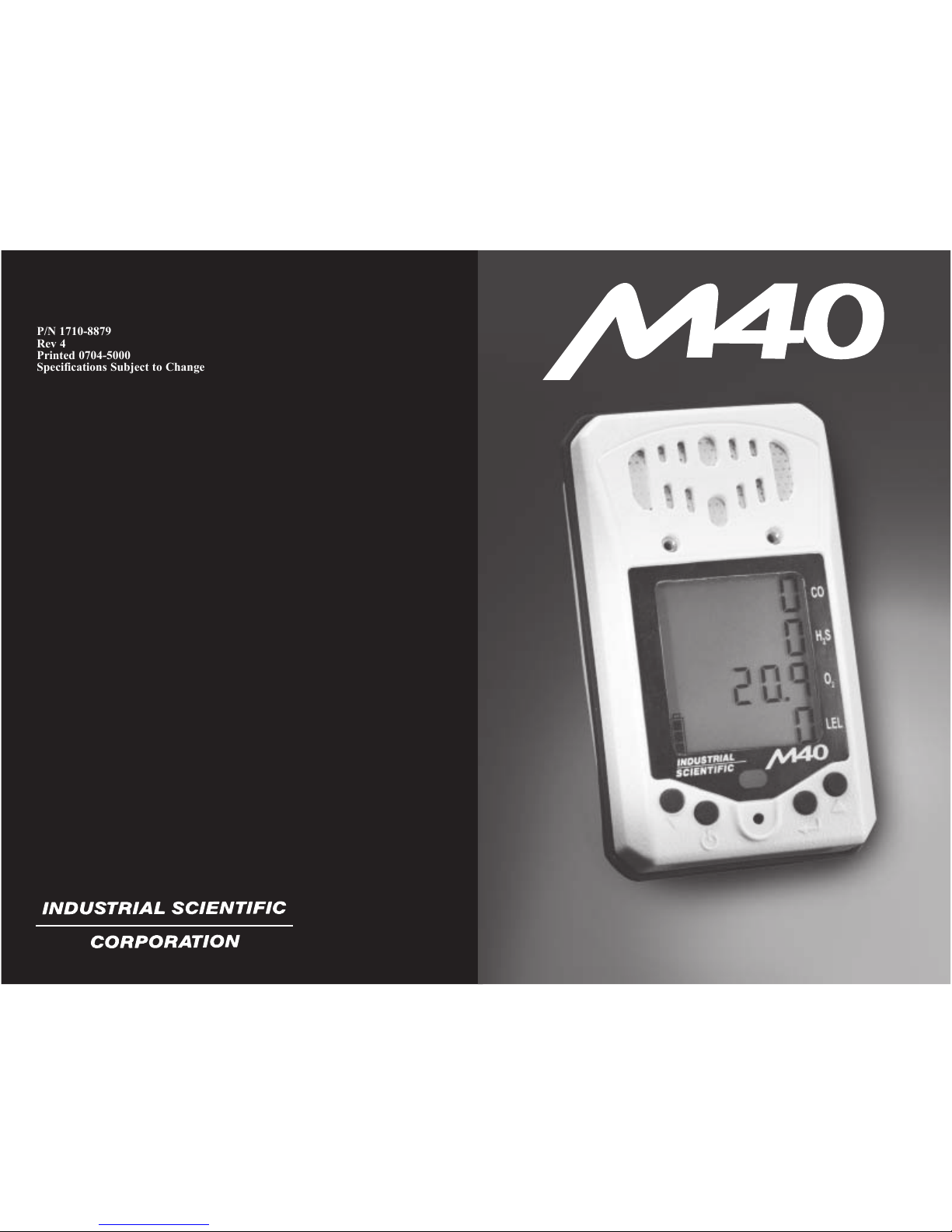
Key
Key
Visual Alarm
Audible Alarm
KeyKey
Sensor Openings
Display
Charger/
Datalink
Port
SP40
Contacts
FRONT
BACK SIDE
I
NSTRUMENT
O
PERATION
To turn on the M40, press and hold the button for 1
second. The unit will emit a single beep and go into a
display test. All icons and segments on the LCD will light.
Next the software revision will be displayed. After this, the
instrument will go into a 20 second countdown. During the
countdown sequence, if the and arrow keys are
pressed simultaneously, the user will enter into the
Configuration Mode. When the countdown is complete, the
M40 will be in its normal Gas Reading Mode. To turn off
the M40 instrument press and hold the button for 5
seconds. The instrument will beep 5 times and then shut off.
M40 GAS READING MODE
Once the M40 enters into the Gas Reading Mode, all 4 gases
(O2, LEL, CO and H2S) will be continuously monitored and
the readings updated on the liquid crystal display. As gas
levels increase, the corresponding reading will reflect the
current gas concentrations. A battery life indicator is also
displayed in the lower left corner. As battery life decreases,
the shaded area of the battery icon decreases. If any of the
gas concentrations exceed the low or high alarm limits (as
well as STEL/TWA), the M40 will go into alarm. When in
alarm, the audible and visual alarms will beep and flash at
set frequencies, and the vibrating alarm will be pulsed.
When the gas concentrations drop below the alarm set
points, the M40 will go back to the Gas Reading Mode.
From the Gas Reading Mode, there are four other modes
that can be accessed. These other modes are reached by
pressing the arrow key.
I
NTRODUCTION
The M40 is a portable gas monitor capable of continuously
and simultaneously monitoring 4 standard gases; O2, LEL,
CO and H2S. Each gas reading is displayed on a custom
graphic LCD. The instrument provides user configurable
low and high alarms as well as STEL and TWA alarms.
When alarm conditions are exceeded, the M40 has audio,
visual and a standard vibrating alarms to alert the user.
98
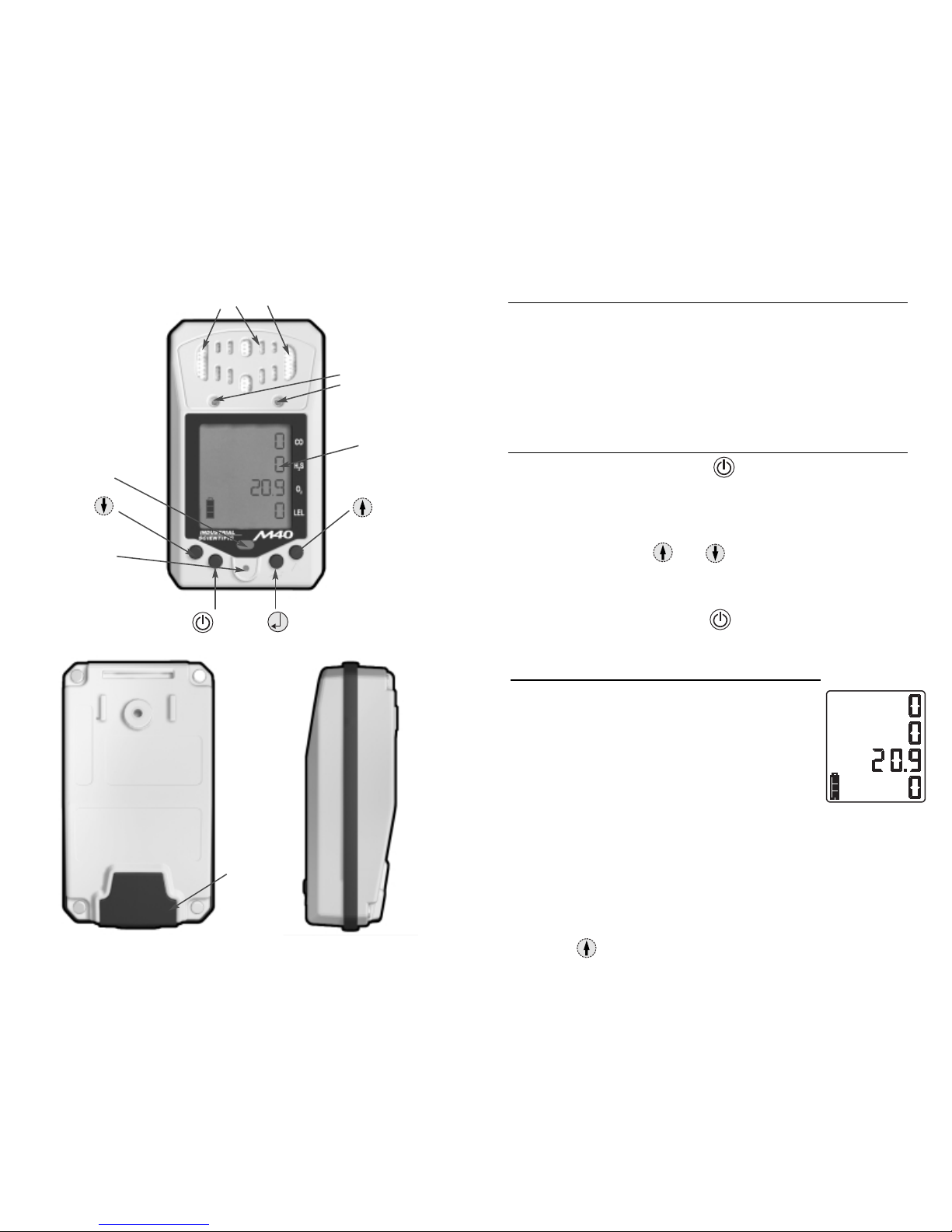
ZERO/CALIBRATION MODE
Pressing the arrow key once from the Gas Reading
Mode will put the M40 in the Zero/Cal Mode. When this
mode is entered, the "Zero" icon and the "Enter" icon will
be displayed along with all four gas readings. Pressing the
arrow key a second time will advance you to the
Display Peaks Mode. Pressing the key will start the
zeroing process. When the CO, H2S, and LEL sensors
have finished the zeroing process, the oxygen sensor will
start to span. During this process, the "Clock" icon and
oxygen full span value will be displayed. When this
process is complete, the instrument will display the "Span"
icon and "Enter" icon. Pressing the key at this time
will cause the M40 to begin calibration for the remaining
sensors. For more information, reference the calibration
section on page 15.
The M40 calibration gases are fixed values. You must
calibrate the instrument on a blended cylinder containing
25 ppm H2S, 100 ppm CO, 25% or 50% LEL Methane or
Pentane, and 19% Oxygen at 0.5 LPM flow.
Note: CSA International compulsory calibration is 50%
LEL Methane.
DISPLAY PEAKS MODE
Pressing the arrow key from the Zero/Calibration
Mode will advance the M40 to the Display Peaks Mode.
When in this mode, the M40 will display the peak gas
readings seen by the toxic and combustible sensor as well
as the lowest reading for the oxygen sensor. The "Peak"
and "Enter" icons are displayed. Pressing the key
will reset all the peak values to the current reading.
TWA
STEL
Gas Reading Mode
Zero/Callibration
Mode
Display Peaks
Mode
View TWA
Mode
View STEL
Mode
O
PERATING
M
ODES

Pressing the and arrow keys simultaneously
during the twenty second countdown will put the M40 into
the Configuration Mode. The Configuration Mode allows
the user to change the Low, High, TWA, and STEL alarm
levels, as well as set the time, date and security code (if
desired). Once the Configuration Mode is entered, a
Security Code screen will be displayed. If no security
code has been set ( 000 ), the M40 will go directly to the
low alarm setpoints. If a security code has been set, use
the and arrow keys to change the value of the
flashing digits to match the code. Once the desired
number is reached for the first digit, press the key to
select the next digit. Continue this process until all three
digits are correct, then press the key. For any
changes made in the Configuration Mode to take affect,
the instrument must be turned off and restarted.
C
ONFIGURATION
M
ODE
1110
VIEW TWA MODE
Pressing the arrow key a third time will put the M40
in the View TWA Mode. The TWA screen will show the
"TWA" icon along with the TWA (Time Weighted
Average) values for the two toxic sensors. TWA values
are reset every time the instrument is powered down, and
the time base is set for 8 hours.
VIEW STEL MODE
Pressing the arrow key a fourth time from the Gas
Reading Mode will put the M40 in the View STEL Mode.
The STEL screen with display the "STEL" icon along
with the STEL values for the two toxic sensors. STEL
(Short Term Exposure Limit) for the toxic sensors will be
reset every time the unit is powered down. The time base
for the STEL is set for 15 minutes.
LOW ALARM SET POINTS
This is the first of the configuration screens. The display
will show the "Buzzer", "Low", "Enter", and
"Up/Down/Enter" icons along with the four low alarm set
points. If no changes are needed, press the arrow
key to move to the next screen. If changes are desired,
press the key. The first low alarm value will be
flashing. To adjust this value, use the and
arrow keys. Once the desired value is met, press the
key to select the next low alarm value. Continue
this process until all four low alarm set points have been
set. Once all four values are set, the display will again
show the "Buzzer", "Low", "Enter", and "Up/Down/Enter"
icons along with the four low alarm set points. Pressing
the key will re-enter the mode and let you set the low
alarm levels again; pressing the arrow key will move
you to the High Alarm Set Points screen. Pressing the
key at any time will take you back to initial Low Alarm
screen, and no changes will be saved. Pressing the
key a second time will take you to the normal Gas
Readings screen. The low alarm is a non-latching alarm.
HIGH ALARM SET POINTS
This is the second of the configuration screens. The
display will show the "Buzzer", "High", "Enter", and
"Up/Down/Enter" icons along with the four high alarm set
points. If no changes are needed, press the arrow
key to move to the next screen. If changes are desired,
press the key. The first high alarm value will be
flashing. To adjust this value, use the and
arrow keys. Once the desired value is met, press the
key to select the next high alarm value.
TWA
STEL

STEL ALARM SET POINTS
The fourth of the configuration screens is the STEL alarm
values. The display will show the "STEL", "Buzzer",
"Low", "Enter", and "Up/Down/Enter" icons along with
the two STEL alarm set points. If no changes are needed,
press the arrow key to move to the next screen. If
changes are desired, press the key. The first STEL
alarm value will be flashing. To adjust this value, use the
and arrow keys. Once the desired value is met,
press the key to select the next STEL alarm value.
Continue this process until both STEL alarm set points
have been set. When both values are set, the display will
again show the "STEL", "Buzzer", "Low", "Enter", and
"Up/Down/Enter" icons along with the two STEL alarm
set points. Pressing the key will re-enter the mode
and let you set the STEL alarm levels again; pressing the
arrow key will move you to the Clock Setting
screen. Pressing the key at any time will take you
back to initial STEL Alarm screen, and no changes will be
saved. Pressing the key a second time will take you
to the normal Gas Readings screen.
CLOCK SETTING
Setting the clock is the next configuration screen. The
display will show the "Clock", "Enter", and
"Up/Down/Enter" icons along with two rows of digits. If
no changes are needed, press the arrow key to move
to the next screen. If changes are desired, press the
key. The first value that will be flashing is the hours
setting of your clock. To adjust this value, use the
and arrow keys. Once the desired value is met, press
the key to select the minutes value. Continue this
process until both hours and minutes have been set. When
both values are set, the display will again show the
"Clock", "Enter", and "Up/Down/Enter" icons along with
the two rows of digits. Pressing the key will re-enter 13
12
Continue this process until all four high alarm set points
have been set. Once all four values are set, the display will
again show the "Buzzer", "High", "Enter", and
"Up/Down/Enter" icons along with the four high alarm set
points. Pressing the key will re-enter the mode and
let you set the high alarm levels again; pressing the
arrow key will move you to the TWA Alarm Set Points
screen. Pressing the key at any time will take you
back to initial High Alarm screen, and no changes will be
saved. Pressing the key a second time will take you
to the normal Gas Readings screen. The high alarm is a
non-latching alarm.
TWA ALARM SET POINTS
This is the third of the configuration screens. The display
will show the "TWA", "Buzzer", "Low", "Enter", and
"Up/Down/Enter" icons along with the two TWA alarm set
points. If no changes are needed, press the arrow key
to move to the next screen. If changes are desired, press
the key. The first TWA alarm value will be flashing.
To adjust this value, use the and arrow keys.
Once the desired value is met, press the key to select
the next TWA alarm value. Continue this process until
both TWA alarm set points have been set. When both
values are set, the display will again show the "TWA",
"Buzzer", "Low", "Enter", and "Up/Down/Enter" icons
along with the two TWA alarm set points. Pressing the
key will re-enter the mode and let you set the TWA alarm
levels again; pressing the arrow key will move you to
the STEL Alarm Set Points screen. Pressing the key
at any time will take you back to the initial TWA Alarm
screen, and no changes will be saved. Pressing the
key a second time will take you to the normal Gas
Readings screen.
TWA
TWA
STEL
STEL

15
14
the mode and let you set the hours and minutes again;
pressing the arrow key will move you to the
Calendar Setting screen. Pressing the key at any
time will take you to the normal Gas Readings screen.
CALENDAR SETTING
Setting the calendar is the configuration screen after the
clock set up. The display will show the "Calendar",
"Enter", and "Up/Down/Enter" icons along with three rows
of digits. If no changes are needed, press the arrow
key to move to the next screen. If changes are desired,
press the key. The first value that will be flashing is
the month setting of your clock. To adjust this value, use
the and arrow keys. Once the desired value is
met, press the key to select the day value. Continue
this process until the month, day and year have been set.
When all three values are set, the display will again show
the "Calendar", "Enter", and "Up/Down/Enter" icons
along with three rows of digits. Pressing the key will
re-enter the mode and let you set the calendar again;
pressing the arrow key will move you to the Security
Code Settings screen. Pressing the key at any time
will take you to the normal Gas Readings screen.
SECURITY CODE SETTING
The next setting is the Security Code Settings. The
display will show the "Closed Lock", "Enter", and
"Up/Down/Enter" icons along with the top row of digits
displaying the current security code. If no changes are
needed, press the arrow key to move to the LEL
settings. If changes are desired, press the key. The
current security code will be flashing. To adjust the first
value, use the and arrow keys. Once the
desired value is met, press the key to select the next
digit. Continue this process until all three digits have been
set. When all three values are set, the display will again
show the "Closed Lock", "Enter", and "Up/Down/Enter"
icons along with the top Security Code. Pressing the
key will re-enter the mode and let you set the security
code again; pressing the arrow key will move you to
LEL Settings. Pressing the key at any time will take
you back to the initial Security Code screen, and no
changes will be saved. Pressing the key a second
time will take you to the normal Gas Readings screen. If a
security code is set, the user will not be able to calibrate
the instrument in the field or make any changes to the
instruments settings without entering the proper code. To
Calibrate the instrument when a security code is set, the
user must turn on the instrument and enter the
Configuration Mode. Once the proper password is
entered, the user can select the Protected Zero/Cal Setting
to zero and calibrate the instrument.
LEL SETTING
The LEL Setting Configuration screen allows the user to
select the LEL calibration gas concentration. After
pressing the key, the LEL and the concentration will
start to flash. Use the to toggle between 25% LEL
and 50% LEL. When the desired concentration is
selected, press the key. Pressing the key will
take you out of the Configuration Mode and into the
normal Gas Reading Mode. Pressing either of the arrow
keys will scroll you through the configuration menus.
PROTECTED ZERO/CAL SETTING
The final configuration screen is a protected zero and
calibration screen. This setting allows the user to zero and
calibrate the instrument when a security code is set. For
more information on how to calibrate the M40, please see
the Zero/Calibration section.
17
16
The M40 comes standard with a continuous loop data logger. The
data logger has enough memory to store 50 hours of data for all four
sensors as well as the temperature. When the 50 hours is exceeded,
the data logger will go back and start overwriting the oldest data in
memory. Data is logged in one minute intervals and can be
downloaded to a PC via the software package and Datalink Module.
Data is extracted from the M40 via a Datalink Module (1810-5528).
To purchase a Datalink Module please contact either you local
distributor of Industrial Scientific Products, or call Industrial
Scientific Corporation at 1-800-DETECTS. To use the Datalink
Module, you must first install the setup software located on the CD
(comes with Datalink). Also make sure there is a fresh battery in the
Datalink Module. Once the Datalink is connected to the M40, and to
the COM port on your PC, click on the "Connect" button to establish
communication. Once communication is established, data can be
downloaded or cleared from the interface menu. To view data, select
"File Open", and to view graphics, select "Graphics" from the
spreadsheet menu. To disconnect at anytime, click on the
"Disconnect" button and unplug the M40.
Note: When a sensor is in an over range condition, a value of 1000
will be logged into the datalog memory for that sensor.
D
ATA
L
OGGING
LEL O
VER
R
ANGE
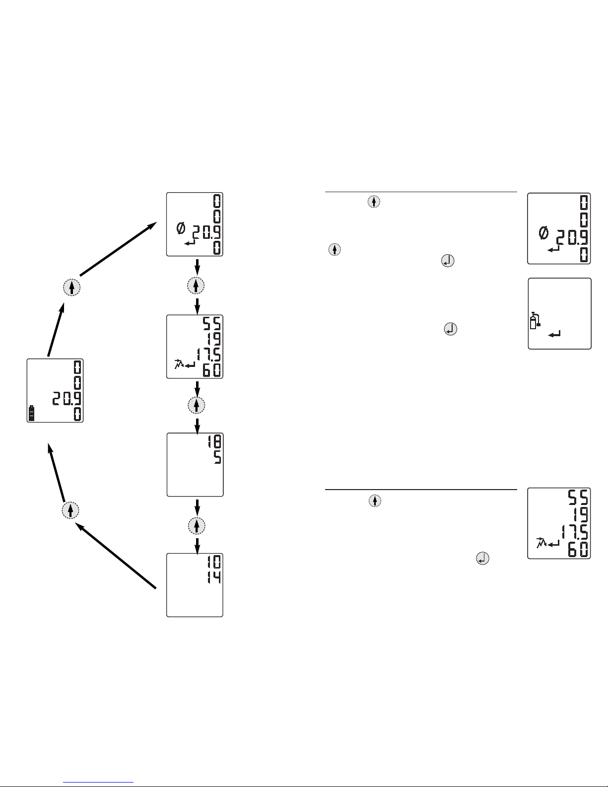
Z
ERO
/C
ALIBRATION
The M40's calibration procedure is a ‘Quick-Cal’
procedure that will calibrate all four sensors
simultaneously with a single blended cylinder of gas. The
‘Quick-Cal’ feature offers calibration times of <60
seconds. The M40 can be calibrated with or without the
external pump. If calibrating with the SP40 pump on the
instrument, please attatch a piece of tubing from the end
of the pump to the demand flow regulator on the blended
gas cylinder. When using a pressure regulator to calibrate
with the SP40 pump, attach the supplied T-fitting/tubing
assembly to the pressure regulator and SP40 pump. If
calibrating without the SP40, securely place the M40 cal-
cup over the sensors. With a piece of tubing, connect the
cal-cup to the regulator on the blended gas cylinder.
Pressing the arrow key once from the Gas Reading
Mode will put the M40 in the Zero/Cal Mode. When this
mode is entered, the "Zero" icon and the "Enter" icon will
be displayed along with all four gas readings. Pressing
the key will start the zeroing process. When the CO,
H2S, and LEL sensors have finished the zeroing process,
the oxygen sensor will start to span. During this process,
the "Clock" icon and oxygen full span value will be
displayed. When this process is complete, the instrument
will display the "Span" icon and "Enter" icon. Pressing
the key at this time will cause the M40 to begin
calibration for the remaining sensors. If this occurs, the
display will flash the "Clock" icon along with the span
values of the sensors. When gas is detected, the display
will show the span readings as well as the "Calibration"
icon. This is a quick calibration (‘Quick-Cal’) process,
and should take no longer than 60 seconds. At the end of
the calibration, the display will flash between the span
readings and a pass/fail indication for ten seconds. Full
span values between 50 and 70 percent are considered
marginal calibrations, and the sensor may soon need
replaced. Full span values less than 50 percent will result
in a failed calibration. To abort calibration at any point in
the process, press the key.
CO
H2S
O2
LEL
The M40 calibration gases are fixed values. You must
calibrate the instrument on a blended cylinder containing
25 ppm H2S, 100 ppm CO, 25% or 50% LEL Methane or
Pentane, and 19% Oxygen at 0.5 LPM flow.
Note: CSA International compulsory calibration is 50%
LEL Methane.
Note: If a security code is set, user will not be able to
calibrate instrument in the field. Please refer to Security
Code Setting for more information.
When an LEL over range condition occurs, the M40 instrument will
enter into an LEL over range condition. This condition is identified
as a continous high alarm. To clear the LEL over range, power down
the M40 and restart it. After any over range it is good practice to
verify the calibration of the combustible gas sensor.

19
18
SP40 S
AMPLING
P
UMP
The SP40 external sampling pump is available for the M40. The SP40 is a parasitic
pump that draws its power from the M40's battery pack. The pump attaches to the
M40 via two captive screws on the face of the M40. The SP40 has a flow rate of .5
SCFH (0.25 LPM), and can draw up to a 50 foot sample. If flow is restricted to the
pump, the M40 will go into a low flow alarm to alert the user.
If the M40 gets a low flow alarm, make sure there are no visible restrictions in the
sampling line. If the unit stays in alarm, the internal dust/water filter should be
replaced. To replace the filter, power down the M40 and remove the end nozzle of the
SP40. Once the nozzle is removed, replace the internal filter. With the new filter in
place, screw the end nozzle back onto the SP40 and power up the M40.
Note: Proper verification of the SP40 flow alarm is recommended before each days
use. To verify operation, restrict flow to the SP40 by blocking the inlet with a finger
and making sure the M40 goes into a flow alarm. A flow alarm is indicated by a high
alarm with a flashing fan icon on the screen.
CHARGING THE BATTERIES
The lithium-ion (Li-ion) battery pack should be fully charged before using the
M40. To charge the internal battery, plug the flying lead of the M40 battery
charger into the charging port located at the bottom of the instrument. This port
is protected with a rubber flap. To ensure proper connection, line up the arrow on
the charger plug with the arrow on the label located on the bottom of the M40.
The battery pack should be fully charged in 5 hours. With a fully charged battery
pack, the M40 typically will run 18 hours in the diffusion mode, or 12 hours with
the SP40. As the battery life decreases, the shaded area of the battery icon will
also decrease. With a maximum of 10 minutes left in the life of the battery, the
M40 will emit a periodic tone alerting you to charge the unit.
M
AINTENANCE
With normal routine maintenance the M40 can be relied upon to provide years of
dependable service. The following guidelines should be followed when performing
maintenance on the M40.
CLEANING
When necessary, wipe the outside of the M40 with a soft, clean cloth. Never
use solvents or cleaning solutions of any type. Make sure the sensor diffusion
membrane is free of debris. Clean sensor openings with a soft, clean cloth or
soft brush.
M40 S
PECIFICATIONS
Size: 4.30" x 2.45" x 1.27" (109mm x 62mm x 35mm)
Weight: 8.6 oz. without SP40 (243 grams)
11.5 oz. with SP40 (326 grams)
Display: Custom Grahic LCD with Backlight
SENSOR SPECIFICATIONS:
Gas Range Resolution T90
Carbon Monoxide (CO) 0-999 ppm 1 ppm 48 sec
Hydrogen Sulfide (H2S) 0-500 ppm 1 ppm 30 sec
Oxygen (O2) 0-30% 0.1% 10 sec
Combustible (LEL) 0-100% LEL 1% 35 sec
TEMPERATURE AND HUMIDITY RANGE:
Operating Temperature: -20ºC to +50ºC (-4ºF to 122ºF),
all sensors
per CSA standard C22.2 No. 152,
LEL sensor tested to 0ºC to 40ºC
(32ºF to 104ºF)
Operating Humidity: 15-95% RH, typical
0-99%, intermittent, non-condensing
Storage Temperature: 0 to 20ºC (32º to 68ºF)
BATTERY SPECIFICATIONS:
Rechargeable Lithium-Ion battery
3.6 Volts, 1.8 Amp/hr.
CHARGER SPECIFICATIONS:
Runtimes:
18 hours diffusion, 12 hours with pump
Runtimes are specified at room temperature with no alarm conditions.

21
20
PART NO. DESCRIPTION
Accessories 1810-5460 SP40 Sampling pump
1810-5528 Datalink
1810-5478 M40 Nylon Carrying Case
1810-5486 M40/SP40 Combination Carrying Case
1810-5494 Compact Charger 120 VAC
1810-5668 Compact Charger 230 VAC
1810-5890 Compact Charger 230 VAC (UK)
1810-5908 Compact Charger 230 VAC (Aus)
1810-5502 12 VDC Automotive Charger
1810-5510 6 Unit Charger
1710-8895 Swivel Belt Clip (standard)
1709-2941 Metal Belt Clip
1710-7582 Suspender Clip
1810-5981 M40 Leather Case
1810-5999 M40/SP40 Combination Leather Case
Calibration Stations
M-CAL 401: Single Unit M40 calibration station:
18105965-10X X = 0 (US plug)
= 1 (UK plug)
= 2 (European plug)
= 3 (Australian plug)
M-CAL 401: Single Unit M40/SP40 combination calibration
station:
18105965-01X X = 0 (US plug)
= 1 (UK plug)
= 2 (European plug)
= 3 (Australian plug)
M-CAL 406: Six Unit Configurable Calibration Station
18105973-ABC A = # of M40 bays (0-6)
B = # of SP40 bays (0-6)
C = 0 (US plug)
= 1 (UK plug)
= 2 (European plug)
= 3 (Australian plug)
Confined Space Kits M40-KIT-11111 M40/SP40 - O2, LEL, CO, H2S
M40-KIT-11101 M40/SP40 - O2, LEL, H2S
M40-KIT-11110 M40/SP40 - O2, LEL, CO
R
EPLACEMENT
P
ARTS
L
IST
W
ARRANTY
Industrial Scientific Corporation's M40 portable gas monitors are warranted to be
free from defects in material and workmanship for a period of two years after
purchase.
The above warranty includes sensors, battery pack, and sampling pump (SP40).
Filters are warranted to be free from defects in material and workmanship for 18
months from date of shipment, or 1 year from date of first use, whichever occurs
first, except where otherwised stated in writing in Industrial Scientific literature
accompanying the product.
LIMITATION OF LIABILITY
INDUSTRIAL SCIENTIFIC MAKES NO OTHER WARRANTIES, EITHER
EXPRESSED OR IMPLIED, INCLUDING BUT NOT LIMITED TO THE
WARRANTIES OF MERCHANTABILITY OR FITNESS FOR PARTICULAR
PURPOSE.
SHOULD THE PRODUCT FAIL TO CONFORM TO THE ABOVE WARRANTY,
BUYER’S ONLY REMEDY AND INDUSTRIAL SCIENTIFIC’S ONLY
OBLIGATION SHALL BE, AT INDUSTRIAL SCIENTIFIC’S SOLE OPTION,
REPLACEMENT OR REPAIR OF SUCH NON-CONFORMING GOODS OR
REFUND OF THE ORIGINAL PURCHASE PRICE OF THE NON-
CONFORMING GOODS.
IN NO EVENT WILL INDUSTRIAL SCIENTIFIC BE LIABLE FOR ANY
OTHER SPECIAL, INCIDENTAL OR CONSEQUENTIAL DAMAGES,
INCLUDING LOSS OF PROFIT OR LOSS OF USE, ARISING OUT OF THE
SALE, MANUFACTURE OR USE OF ANY PRODUCTS SOLD HEREUNDER
WHETHER SUCH CLAIM IS PLEADED IN CONTRACT OR IN TORT,
INCLUDING STRICT LIABILITY IN TORT.
It shall be an express condition to Industrial Scientific’s warranty that all products
be carefully inspected for damage by Buyer upon receipt, be properly calibrated for
Buyer’s particular use, and be used, repaired, and maintained in strict accordance
with the instructions set forth in Industrial Scientific’s product literature. Repair or
maintenance by non-qualified personnel will invalidate the warranty, as will the use
23
22
of non-approved consumables or spare parts. As with any other sophisticated
product, it is essential and a condition of Industrial Scientific’s warranty that all
personnel using the products be fully acquainted with their use, capabilities and
limitations as set forth in the applicable product literature.
Buyer acknowledges that it alone has determined the intended purpose and
suitability of the goods purchased. It is expressly agreed by the parties that any
technical or other advice given by Industrial Scientific with respect to the use of
the goods or services is given without charge and at Buyer’s risk; therefore,
Industrial Scientific assumes no obligations or liability for the advice given or
results obtained.
Copyright
2003 © Industrial Scientific Corporation
All rights reserved.These help materials or any part thereof may not, without the
written consent of Industrial Scientific Corporation, be copied, reprinted or reproduced
in any material form including but not limited to photocopying, transcribing, transmitting
or storing it in any medium or translating it into any language, in any form or by any
means, be it digitally, electronic, mechanical, xerographic, optical, magnetic or
otherwise.
The information contained in this document is proprietary and confidential and all
copyright, trade marks, trade names, patents and other intellectual property rights in
the documentation are the exclusive property of Industrial Scientific Corporation
unless otherwise specified.The information (including but not limited to data, drawings,
specification, documentation, software listings, source or object code) shall not at any
time be disclosed directly or indirectly to any third party without prior written consent.
The information contained herein is believed to be accurate and reliable. Industrial
Scientific Corporation accepts no responsibility for its use by any means or in any way
whatsoever Industrial Scientific Corporation shall not be liable for any expenses, costs
by damage that may result from the use of the information contained within this
document.The information contained herein is subject to change without notice.
Table of contents
Other Industrial Scientific Monitor manuals


