Industrial Scientific T40 II User manual

Portable Single Gas Monitor
Product
Manual
The Essential Guide for
Safety Teams and
Instrument Operators
Edition: 2.3
Sep 27, 2022
Part Number: 17160575-1

1
Content
1. Certifications................................................................................................................. 2
2. Warnings and cautionary statements........................................................................ 3
3. Product Overview......................................................................................................... 3
3.1 Product Specifications......................................................................................... 4
3.2 Hardware Overview............................................................................................. 5
4. Operation and Instructions ......................................................................................... 6
4.1 Display Overview................................................................................................. 6
4.2 Start-up, Shutdown and Always on..................................................................... 8
4.3 Configuration mode ............................................................................................. 8
4.4 Operation mode................................................................................................. 13
4.5 Bump test (or "functional test").......................................................................... 15
4.6 Zeroing............................................................................................................... 16
4.7 Calibration.......................................................................................................... 17
5. Alarms and Notifications.......................................................................................... 18
6. Replace the battery .................................................................................................... 19
7. Warranty Policy .......................................................................................................... 20
8. Limitation of Liability ................................................................................................. 20

2
1. Certifications
Directive
or CB
Area Classifications
Approved
Temperature
Range
Standards
IECEx
Ex ia IIC T4 Ga
Ex ia I Ma
-40 ° C to +50 ° C
-40 ° F to +122 ° F
IEC 60079-0:2017 Ed.7.0
IEC 60079-11:2011 Ed.6.0
ATEX
Ex ia IIC T4 Ga
Ex ia I Ma
-40 ° C to +50 ° C
-40 ° F to +122 ° F
EN IEC 60079-0:2018
EN 60079-11:2012
UL
Class I, Division 1,
Groups A, B, C, D T4
Class I, Zone 0, AEx ia
IIC T4 Ga
-40 ° C to +50 ° C
-40 ° F to +122 ° F
ANSI/UL 60079-0-2020 Ed.7
ANSI/UL 60079-11-2018 Ed.6
ANSI/UL 913-2019 Ed.8
UL 61010-1 3rd Edition (2012),
AMD1: 2018
CSA
Ex ia IIC T4; Class I,
Division 1, Groups A,
B, C, D T4
-40 ° C to +50 ° C
-40 ° F to +122 ° F
CAN/CSA C22.2
No. 60079-0:19
CAN/CSA-C22.2
No. 60079-11:14 (r2018)
CAN/CSA C22.2 No.61010-1-12,
UPD1: 2015, UPD2: 2016,
AMD1: 2018
China
Ex
Ex ia IIC T4 Ga
-40 ° C to +50 ° C
-40 ° F to +122 ° F
GB/T 3836.1- 2021
GB/T 3836.4- 2021
GB/T 4208-2017
China
CPA
Metrological
-10 ° C to +40 ° C
14 ° F to +104 °F
JJF 1363-2019
JJF 1421-2013
China
MA
Ex ia I Ma
-20 ° C to +40 ° C
-4 ° F to +104 °F
MT 703-2008
GB/T 3836.1-2021
GB/T 3836.4-2021
3
2. Warnings and cautionary statements
For maximum safety and optimal performance, read and understand the manual
before operating or servicing the unit. Failure to perform certain procedures or note
certain conditions may impair the performance of this product.
For safety reasons, this equipment must be operated and serviced by qualified
personnel only. Customer site assembly is not recommended, improper disassembly
may reduce the performance of the instrument.
Substitution of components may impair intrinsic safety and may cause an unsafe
condition.
DO NOT REPLACE BATTERY WHEN AN EXPLOSIVE ATMOSPHERE IS
PRESENT. USE ONLY RAMWAY ER14335 BATTERIES.
Before use, ensure that the ESD film on the LCD display and label is not damaged or
peeling.
Obstruction of sensor openings–due to dust, dirt, water, or another cause–can inhibit
the unit’s ability to measure gas concentrations accurately. When this occurs,
readings may appear lower than the actual gas concentration. Keep sensor openings
clean, dry, and properly exposed to the ambient air.
Obstructed, contaminated, or damaged sensor water barriers (or their gaskets) can
inhibit the unit’s ability to measure gas concentrations accurately. When this occurs,
readings may appear lower than the actual gas concentration. Contact after-sales
service to replace the sensor water barriers and gaskets as needed.
Service the unit, use its communications port, and change its battery cell only in
nonhazardous locations. Not for use in oxygen-enriched atmospheres.
Contact your service representative immediately if you suspect that the unit is working
abnormally.
3. Product Overview
T40 II single gas monitor is compact, easy to carry and use. It is specially designed to detect the
concentration toxic gases, and mainly used in Petrochemical industry and coal mine. The monitor can
continuously monitor the concentration of harmful gas in the surrounding environment, once the gas
concentration reaches the low and high alarm and TWA/STEL alarm preset values, T40 II will produce
sound, light and vibration alarms

4
3.1 Product Specifications
Item
Description
Display
Segment LCD
Keypad buttons
Two buttons
Technology
Electrochemical
Battery Pack
Replaceable RAMWAY ER14335 3.6 V Primary Lithium-thionyl chloride
(Li-SOCl2) battery cell, 1.65AH, 2/3AA. Two-yearsarun time
Case materials
polycarbonate with a protective rubber over-mold
Alarms
Visual alarm (two red LEDs). Audible alarm(95 dB). Vibration alarm
Ranges
Carbon Monoxide (CO)
0-1000 ppm
0-2000 ppm
Hydrogen Sulfide(H2S)
0-100 ppm
0-200 ppm
0-500 ppm
Display resolution
1 ppm
0.1 ppm
Calibration gas and
concentration
100 ppm CO
25 ppm H2S
Response Time
<10s
<10s
Dimensions
82 x 60 x 27 mm (3.23 " x 2.36 " x 1.07 ")
Weight
85 g ( 3.0 oz.), typical
Ingress protection
IP66 / IP68
Operating Tempc
-40 ° C to +50 ° C (-40° F to +122 ° F)
Operating humidity
5 to 95% relative humidity (RH) noncondensing
Pollution Degree
2
Maximum use
altitude
5000m above sea level
aDepending on operating conditions; the amount of time the unit is in alarm; and the enablement of
unit's confidence indicator.
bApply when the instrument is calibrated using the stated calibration gas and concentration; accuracy
is equal to the stated percentage.
c Operating temperatures below -20° C may cause reduced instrument accuracy and affect display and
alarm performance.
5
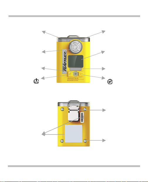
3.2 Hardware Overview
T40 II
Visual alarm indicator
Front
Visual alarm indicator
Sensor port
LCD Screen
Buzzer
On-off/mode button
Gas label
Enter/Edit button
Back
Clip
Serial number and
certificate label
Screw
Hardware overview
6
4. Operation and Instructions
The table below list that Industrial Scientific's minimum frequency recommendations for each program.
These recommendations are based on site data, safe work procedures, industry best practices and
regulatory standards to help ensure worker safety. Users can reduce the frequency of the following
procedures as appropriate according to the safety policy of local government or company, Industrial
Scientific is not responsible for developing security practices and policies.
Procedure
Recommended minimum frequency
Configuration
Before first use, when there is a change in the installed sensor type, and as
otherwise needed.
Calibration
Before first use and 6month interval, depending on use and exposure to
gas and contamination, such as vibration, drop or sensor replacement,
multiple high concentration gas shocks,etc.
Bump test
Prior to each day’s use.
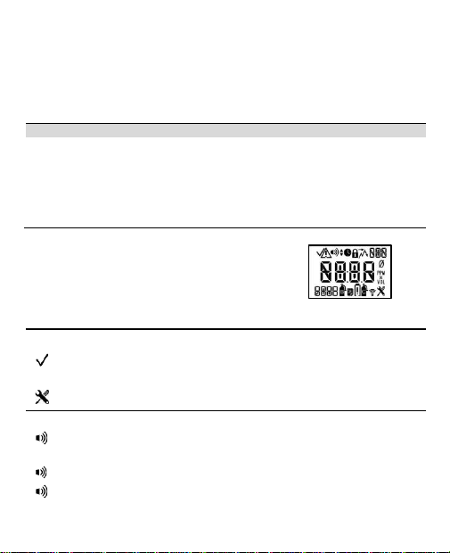
4.1 Display Overview
The visual test screen depicted right shows all the indicators that
can appear on the display screen. Each indicator is stationary and
appears only when relevant to the task being performed.
Display screens, indicators, and abbreviations
Status indicators
Instrument work normally.
!
Instrument failure.
The unit is in configuration mode.
Alarm indicators
The alarm icon is used in combination with other indicators to communicate a
variety of conditions.
and ▲
High-level gas alarm.
and ▼
Low-level gas alarm.
7
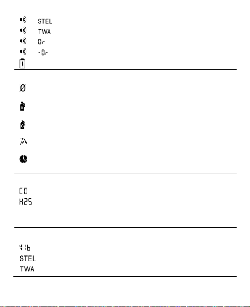
and
STEL alarm.
and
TWA alarm
and
Positive over-range gas alarm.
and
Negative over-range gas alarm.
Low-battery alarm.
Process and time-based indicators
The zero icon is used in combination with other indicators to communicate
sensor zero information.
The bump test icon is used in combination with other indicators to
communicate bump test information.
The calibration icon is used in combination with other indicators to
communicate calibration information.
The peak reading is the highest detected gas reading. Always clear the peak
reading after calibration.
A process is in progress. In configuration mode, indicates a time-based
setting (e.g. bump test response time).
Gas name and unit-of-measure abbreviations
Carbon Monoxide (CO)
Hydrogen Sulfide (H2S or H2S)
PPM
Parts per million is the unit of measure for CO and H2S,PPM is the volume
ratio in describing the gas concentration, 1ppm=10-6 equivalent to 1umol/mol.
Other abbreviations
Vibration alarm enabled.
Short-term exposure limit, default time 15minutes. Display variations: “STEL”
Time-weighted average. default time 8h. Display variations: “TWA”

8
4.2Start-up, Shutdown and Always on
Start-up
Press and hold the for 3 seconds, the instrument starts to power on. After power on, the instrument
automatically enters the visual test, firmware version, 20-second countdown and the second visual test
screen, and is accompanied by warning sound and light test. After a short warm-up, it will automatically
enter the real-time gas monitoring screen.
Visual test screen
Version
Countdown
Shutdown and always on
Countdown
Press and hold for five seconds.
After a five-second countdown:
The instrument powers off if;
•the always-on feature is disabled or
•the always-on feature is enabled and the security code is set
to 000.
Enter security code
If this screen is activated, the shutdown process is security-
code protected. To complete shutdown, the user must enter the
correct three-digit code.
Value range: 000 to 999
4.3 Configuration mode
Configuration mode can only be accessed during startup, at the 20 second countdown screen, press
and hold both buttons simultaneously more than 1second to enter configuration mode, select alarm
and warning related options that maximize safety within the air sampling environment.
When the unit is in configuration mode, the following apply:
•The tool icon ( ) displays in the lower right corner of each screen.
•With successive short presses of the on-off button( ), the user can scroll through the
configuration loop.
•The enter button ( ) is used to start the editing process or initiate zero.
•When editing a value, the enter button ( ) increments the value and the on-off-mode
button ( ) saves the value.
9
•When editing a value, once the last value in the range is reached, the display starts again
with the first value.
•When buttons ( ) is pressed and held more than 1 seconds, the unit leaves configuration
mode; it enters operation mode and the home screen is activated.
•Unless otherwise noted, when no button is pressed for 30 seconds, the unit enters operation
mode and the home screen is activated.
•Any changes made in configuration mode are automatically saved to the unit and take effect
immediately.
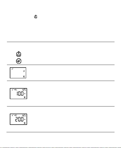
Configuration instructions
Buttons or
Screen
Button effects or Screen Description
Saves the currently displayed value or activates the next configuration
mode screen.
Increase value or First press activates the value. Continued presses
increment the value; hold to speed the increment pace.
Initiate zero
This screen allows the technician to complete the zero and calibration
processes from configuration mode.
Low gas alarm setpoint
This screen features the status, low alarm, sensor-type, and configuration
icons, with the alarm's current setpoint and unit of measure. Edit the alarm
setpoint based on the following:
Value range = starts at minumum sensor measurement resolution, ends at
the high gas alarm setpoint value.
Value increment = sensor measurement resolution
High gas alarm setpoint
This screen features the status, high alarm, sensor-type, and configuration
icons, with the alarm's current setpoint and unit of measure. Edit the alarm
setpoint based on the following:
Value range = starts at low gas alarm setpoint value, ends at the highest
measurement range value of the sensor.
Value increment = sensor measurement resolution
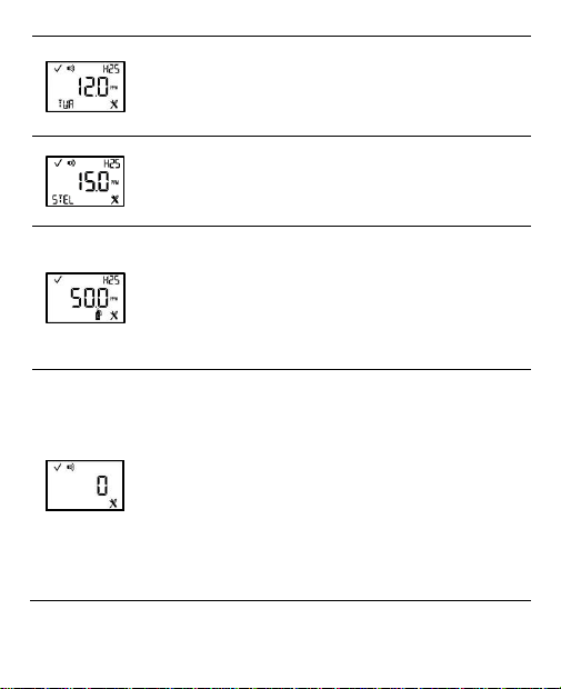
10
TWA alarm setpoint
This screen features the status, alarm, sensor-type, configuration, and
TWA icons, with the alarm's current setpoint and unit of measure. The
alarm setpoint can be edited.
Value increment = within the sensor measurement resolution
STEL alarm setpoint
This screen features the status, alarm, sensor type, configuration, and
STEL icons, with the current setpoint. The alarm setpoint can be edited.
Value increment: sensor measurement resolution
Calibration gas
This screen features the status, sensor-type, configuration, and calibration
icons, with the current calibration gas setting in the main area.
This setting reflects the concentration of calibration gas that the instrument
expects to read when calibrated; it should be edited to match the cylinder's
gas concentration.
Value range: within the sensor measurement range
Value increment: sensor measurement resolution
Confidence indicator
This screen features the status, alarm, and configuration icons, with the
selected setting value displayed in the main area. The technician can
disable or enable the indicator and choose the indicator type.
When enabled, the unit will emit the selected signal every 90 seconds in
operation mode.
Note: When options 1, 2, or 3 are selected, the expected battery life will be
reduced.
Values:
0 = disabled
1 = audible chirp enabled
2 = LED flash enabled
3 = audible chirp and LED flash enabled

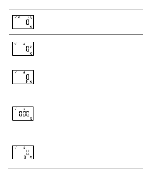
11
Operation-mode bump test
This screen features the status, lock, configuration, and bump test icons,
with the selected setting value displayed in the main area. The technician
can enable or disable this operation mode feature.
When enabled, the instrument operator can bump test the unit from
operation mode.
Values:
0 = disabled ,1 = enabled
Bump test percentage
This screen features the status, configuration, and bump test icons, with
the current setting value displayed in the main area. The technician can set
the percentage of calibration gas to which the unit will respond.
Value range: 50% to 95%
Value increment: 1%
Bump test response-time
This screen features the status, clock, configuration, and bump test icons,
with the current setting in seconds displayed in the main area. A sensor
passes a bump test when it senses the specified percentage of calibration
gas within the specified response time setting.
Value range: 30 to 120 seconds
Value increment: 5 second
Alarm latch
This screen features the status, alarm, lock, and configuration icons, with
the current setting displayed in the main area. The technician can enable
or disable this operation-mode feature.
When disabled, a unit in alarm will turn off its alarm when the gas reading
is no longer at the alarm-producing concentration.
When enabled, a unit in alarm will remain in alarm until it is manually reset.
The instrument operator can reset a latched alarm from gas normal reading
screen by click button.
Values:
0 = disabled ,1 = enabled
12
Vibration alarm
This screen features the status, alarm, “VIb”, and configuration icons, with
the selected setting value displayed in the main area. When enabled, the
vibrating alarm will be activated when the unit is in alarm.
Values: 0 = disabled ,1 = enabled
Operation-mode zero
This screen features the status, lock, zero, and configuration icons. The
technician can enable or disable this operation-mode option.
When enabled, the instrument operator can zero the unit from operation
mode.
Values: 0 = disabled ,1 = enabled
Operation-mode calibration
This screen features the status, lock, configuration, and calibration icons.
The technician can enable or disable this operation-mode option.
When enabled, the instrument operator can calibrate the unit from
operation mode.
Values:0 = disabled ,1 = enabled
Security code
This screen features the status, lock, and configuration icons, with the
current security code displayed in the main area. The security code
controls access to a unit's configuration mode and the ability to power off a
unit that is configured for always-on operation.
If the security code is set at 000, entry to configuration mode is not
security-code protected, and an always-on unit can be powered off without
a security code. Any other value will enable the security code.
Value range: 000 to 999
Value increment: 1
Always-on
This screen features the status, lock, configuration, and the battery icon.
The technician can enable or disable this feature.
When enabled, the entry of the unit's security code (if the security code is
not 000) will be required to complete the shutdown process.
Values:
0 = disabled ,1 = enabled
13
4.4 Operation mode
In the operation mode, the worker can scroll through the operating mode loop by continuously pressing
the on/off button ( ). The zeroing, calibration, and alarm function test procedures can only be
completed if these task settings are enabled for operating mode access。
TWA, STEL (if operating mode access is enabled) and peak readings can also be viewed and cleared.
When the reading summary is cleared, CO and H2S value resets to zero.
In operation mode, the following apply:
•Press to scroll through the operation-mode loop.
•Press to initiate a task or to clear a reading.
•A long press on will reset a latched alarm; it does not disable an enabled latch.
•Except where noted, when no button is pressed for 30 seconds, the home screen is
activated。
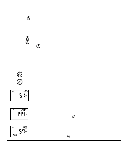
Operation instructions
Buttons or
Screen
Button effects or Screen Description
Saves the currently displayed value or activates the next configuration
mode screen.
Increase value or First press activates the value. Continued presses
increment the value; hold to speed the increment pace.
Gas monitoring
This screen (numeric shown) features the check mark and sensor-type
icons, the current gas reading, and unit of measure.
The check mark indicates the unit is operational and there are no sensor
faults.
Peak reading
This screen features the check mark, peak, and sensor-type icons, and the
most recent peak reading, Press clear the reading then the value reset
to 0 .
TWA reading
This screen displays when the TWA reading is enabled in operation-mode.
The screen features the check mark, sensor-type, and TWA icons, and the
current TWA reading. Press clear the reading then the value reset to 0 .

14
STEL reading
This screen displays when the STEL reading is enabled in operation-mode.
The screen features the check mark, sensor-type, and STEL icons, and the
current STEL reading. Press clear the reading then the value reset to 0 .
Initiate bump test
This screen displays when operation-mode bump testing is enabled. The
screen features the check mark and bump test icons.
Initiate zero
This screen displays when operation-mode zeroing is enabled. It features
the check mark and zero icons.

15
4.5 Bump test (or "functional test")
Bump testing is a functional test in which an instrument's installed
sensors are to be briefly exposed to (or “bumped” by) calibration
gases in concentrations that are greater than the sensors’ low-
alarm setpoints. This will cause the instrument to go into low
alarm and will indicate which sensors pass or fail this basic test
for response to gas.
Note:If fails the bump test, please perform a calibration. If failes
the calibration, please contact Industrial Sicentific after-sales
service.
Bump test instructions
Screen
Screen Description
Initiate bump test
From anywhere in the operation-mode loop, press until the initiate bump
test screen is activated.
Press to start the bump test process. Press to cancel the bump test.
Bump test apply gas
Once the bump test is started, the apply-gas screen is activated; the
expected type and concentration of calibration gas are displayed.
This screen remains activated for up to 5 minutes as the unit awaits the
application of calibration gas.
Bump test in progress
Bump test results
If fail the bump test, need to calibrate the instrument.
If pass the bump test, the home screen will be automatically activated.
note
:
Close the cylinder and remove the calibration cup after bump test.

16
4.6 Zeroing
Zeroing adjusts the sensors’ “baseline” readings, which become the
points of comparison for subsequent gas readings. It is a prerequisite
for calibration. During zeroing, the installed sensors are to be
exposed to an air sample from a zero-grade-air cylinder or ambient
air that is known to be clean air. If there are gases in the air sample
that are below the lowest alarm level, the instrument will read them
as zero; its task is to read the air sample as clean air. The user's task
is to ensure the air is clean.
Zeroing instructions
Screen
Screen Description
Initiate zero
From anywhere in the operation-mode loop, press until the initiate-zero
screen is activated.
At the initiate-zero screen, press to start the zero process.
Zero in-progress
While the sensors are zeroed, the zero-in-progress screen is activated.
Note
:
Must be zeroed in fresh air.
Zero results
After the sensors are zeroed, the zero-results screen is activated, and an
audible alert is emitted.
If the result is an "F" for fail, press to reactivate the initiate-zero screen.
Repeat the zero process.
If the result is a "P" for pass, press to display the initiate-calibration
screen. If calibration is not desired, press twice or wait approximately 30
seconds to active home screen.

17
4.7 Calibration
Regular calibrations promote the accurate measurement of gas
concentration values. During calibration, an instrument’s installed
sensors are to be exposed to their set concentrations of calibration
gases. Based on the sensors’ responses, the instrument will self-
adjust to compensate for declining sensor sensitivity, which naturally
occurs as the installed sensors are used or “consumed”.
Calibration instructions
Screen
Screen Description
Initiate calibration
press button at zero results screen to enter the intiate calibration
screen, then press button to start the calibration.
To cancel the calibration, press button.
Calibration apply gas
Once calibration is started, the apply-gas screen is activated; the expected
type and concentration of calibration gas are displayed.
This screen remains active for up to 5 minutes as the unit awaits the
application of calibration gas.
To cancel calibration, press button.
Calibration in progress
Note
:
Need to open the calibration gas cylinder regulator before
calibration.
Calibration results
If passes calibration, Result screens are alternately activated and displays
the span reserve value.
If fails calibration, the audible, visual, and vibrating alarms turn on. Results
screens are alternately activated; one indicates the fail results and the
other displays the span reserve value.
note
:
Close the cylinder and remove the calibration cup after calibration.
18
5. Alarms and Notifications
Alarms notify the instrument operator of danger.Warnings notify of a condition that needs attention.
Take seriously all alarms, warnings, and indicators, and respond to each according to company policy.
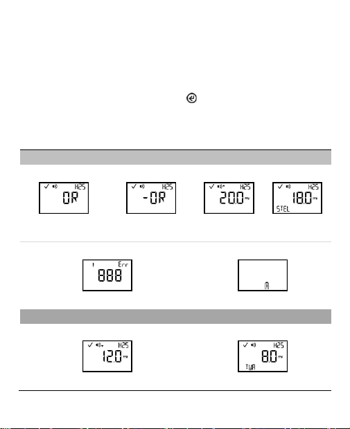
Alarms
T40 II gas monitors have alarms of two different intensities, high and low. Alarms are persistent: they
turn off when the alarm-causing event is no longer detected, however, if the instrument’s alarm latch is
enabled, an alarm will remain on until the user presses to turn it off.
When all alarm signals are on:
•The high alarm features the red lights, with steady sound. It is fast-paced.
•The low alarm is similar to the high alarm, but it is medium-paced.
Note: Signals (visual, audible, and vibration) vary based on instrument settings.
Alarm Level : High
Gas Present (H2S is shown.)
Gas present, over-
range alarm
Gas present, negative
over-range alarm
Gas present,
high alarm
STEL alarm
System alarm
System alarm
Critical low-battery alarm
Alarm Level: Low
Gas Present
Gas present, low alarm
TWA alarm

19
Notifications
Warnings persist until the event is resolved. In some cases, an
unresolved warning will become more urgent in frequency. For
example, a low-battery warning that is not resolved will change
to alarm status indicating a critical low-battery condition.
Low-battery warning
6. Replace the battery
When the battery has 12 to 72 hours left, T40 II display Low-battery
warning notification and emit 1 beep, visual and vibration alarm every
1minute. The users need contact Industrial Scientific or qualified
person to replace the battery.
1. Using a T10 Torx screwdriver, remove all four screws from the
case bottom; set aside the screws.
2. Lift the battery up from its cradle. Dispose of according to
company policy.
3. Orient the replacement battery so the positive and negative ends align with the "+" and "-" cradle
markings, respectively. Place the new battery into the cradle negative end first. Press down on
the battery to secure it in the cradle.
Note: Use RAMWAY ER14335 battery only.
Use Do not replace battery when an explosive atmosphere is present.
Work on a nonconductive surface in a well-lit area.
Wear grounding straps to prevent electrostatic discharge (ESD), which can cause damage
to the instrument's electronics.
Be sure to turn off the instrument before servicing the unit or replacing the battery.
+
-
Table of contents
Other Industrial Scientific Monitor manuals


