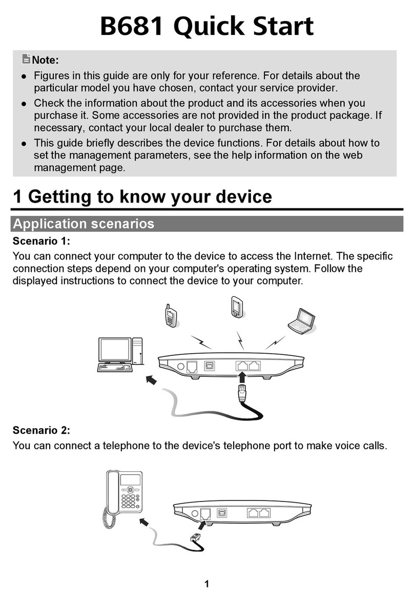
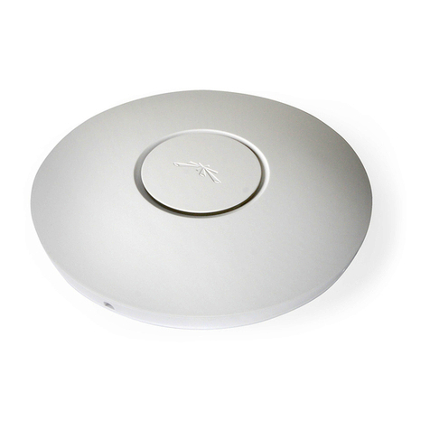
INEW Digital Company IN-ROUTER-UW User manual

Product Manual Page 1 of 21
Wireless Internet for more comfortable, more fast and more easily
Make your network on Internet wirelessly
IN-ROUTER-UW Manual
Cross Wireless AP to USB Router
INEW Digital Company
TEL: 82-42-933-7328
FAX: 82-42-934-4829
www.inewdc.com

Product Manual Page 2 of 21
Wireless Internet for more comfortable, more fast and more easily
Make your network on Internet wirelessly
FCC STATEMENT
FCC NOTICE: This device complies with part 15 of the FCC rules. Operation is
subject to the following two conditions: (1) This devices may not cause harmful
interference, and (2) This device must accept any interference received, including
interference that may cause undesired operation.
This equipment has been tested and found to comply with the limits for a Class B
digital device, pursuant to part15 of the FCC Rules. These limits are designed to provide
reasonable protection against harmful interference in a residential installation. This
equipment generate, uses and can radiate radio frequency energy and, if not installed
and used in accordance with the instructions, may cause harmful interference to radio
communications. However, there is no guarantee that interference will not occur in a
particular installation. If this equipment does cause harmful interference to radio or
television reception, which can be determined by turning the equipment off and on,
the user is encouraged to try to correct the interference by one or more of the following
measures:
• Reorient or relocate the receiving antenna.
• Increase the separation between the equipment and receiver.
• Connect the equipment into an outlet on a circuit different from that to which the
receiver is connected.
• Consult the dealer or an experienced radio/TV technician for help.
Caution: Any changes or modifications to the equipment not expressly approved by
the party responsible for compliance could void user’s authority to operate the
equipment.
FCC Radiation Exposure Statement: This equipment complies with FCC radiation
exposure limits set forth for an uncontrolled environment. This equipment should be
installed and operated with minimum distance 20cm between the radiator & your body.
End users must follow the specific operating instructions for satisfying RF exposure
compliance. This transmitter must not be co-located or operating in conjunction with
any other antenna or transmitter. IEEE 802.11b or 802.11g operation of this product in
the U.S.A. is firmware-limited to channels 1 through 11.

Product Manual Page 3 of 21
Wireless Internet for more comfortable, more fast and more easily
Make your network on Internet wirelessly
Table of Contents
Copyright………………………………………………………………………………………………………………….4
Purpose…………………………………………………………….………………………………………………………4
1. Introduction.………………………………………………….…………………………………………………………5
1.1 IN-ROUTER-UW Overview…………………………………………………………………………….5
1.2 Appearance………………………………………………………………………………………………………6
1.3 Features……………………….………………………………………………………………………………….7
1.4 Specification…………………………………………………………………………………………………….8
2. Composition……………………………………………………………………………………………………………11
3. Operation process………………………………………………………………………………………………….12
3.1 PPP mode……………………………………………………………………………………………………….12
3.2 PPPoE mode…………………………………………………………………………………………………12
4. Setting Host PC………………………………………………………………………………………………………14
3.1 Setting Host PC……….…….………………………………………………………………………………14
5. Connecting with IN-ROUTER-UW’s web configuration page………………………………16
6. PPP mode Configuration…………………………………………………………………………………………18
7. Firmware Upgrade…………………………………………………………………………………………………20

Product Manual Page 4 of 21
Wireless Internet for more comfortable, more fast and more easily
Make your network on Internet wirelessly
Copyright
This Product manual describes features including hardware, software and operation
and so on. INEWDC has made best effort to ensure that the information contained in
this document is accurate and reliable. This document is the property of INEWDC and
implies no license under patents, copyrights, trade secrets. No part of this publication
should be copied, reproduced, stored in a retrieval system, or transmitted, in any form
or by any means (electronic, mechanical, photographic, or otherwise) without the prior
permission of INEWDC.
Purpose
This manual includes how to configure and use the IN-ROUTER-UW.

Product Manual Page 5 of 21
Wireless Internet for more comfortable, more fast and more easily
Make your network on Internet wirelessly
1. Introduction
1.1 IN-ROUTER-UW Overview
IN-ROUTER-UW, Cross Wireless AP to USB Router performs data communication
functions between LAN(Local Area Network) and wireless WAN(Wide Area Network)
using USB type mobile modem like IS-95A/B, CDMA2000-1x EVDO CDMA Cellular
station for Small Office Home Office. IN-ROUTER-UW incorporates embedded OS
including various network protocols, Wireless AP, USB Host functionality and an
Ethernet regular interface.
IN-ROUTER-UW connects directly to local network system like PC with wireless LAN
card, other router utilizing an Ethernet interface for the purpose of wireless Internet
or network.
Range of supply voltage is from 6~30 [VDC] which provides compatibility for
platforms utilizing various industry application.
Below the figure 1 shows an application of network system architecture using IN-
ROUTER-UW.
[Figure 1. Network system architecture of IN-ROUTER-UW]

Product Manual Page 6 of 21
Wireless Internet for more comfortable, more fast and more easily
Make your network on Internet wirelessly
1.2 Appearance
Below the figure 2 shows appearance and the each part of name of IN-ROUTER-UW.
[Figure 2. Each part name of IN-ROUTER-UW]

Product Manual Page 7 of 21
Wireless Internet for more comfortable, more fast and more easily
Make your network on Internet wirelessly
1.3 Feature
zOne USB Host for external mobile modem technologies like CDMA, WCDMA,
GSM, HSDPA etc
zOne USB Host for the storage USB device
zWireless AP compliant IEEE802.11b/g
zA 10/100Mbps Ethernet Port
zA 32-bit RISC Network System on Chip
zAdopt Embedded Operating System
zSystem clock 100MHz(CPU) and 96MHz(BUS)
zPower LED, Network LED, USB 1_OVC, USB 2_OVC LED
zA external Reset switch(Factory default is coming soon.)
zDHCP Server
- Getting IP address automatically from internal DHCP Server
zNAT(Network Address Translation)
- Make the client with private IP Address connect on Internet.
zSNMP
- Monitoring Network compatible with standard MIB II.
zS/W upgrade
- Remote updating via HTTP
- Console updating via DB(Debug Board) is available
zWide Range input voltage
- Supplying voltage from 8 to 30[VDC] is available.
z24-Pin diagnostic port
- Simple UART_1: Console port for managing and monitoring IN-ROUTER-UW
Upgrading IN-ROUTER-UW’s firmware.
- Simple UART_2: an external UART

Product Manual Page 8 of 21
Wireless Internet for more comfortable, more fast and more easily
Make your network on Internet wirelessly
1.4 Specification
1.4.1 Mechanical Specification
Dimensions 141 x 93 x 27 [mm], include side bracket
Weight Approx. 220 [g]
Housing Material CASE – A6010 , Brackets – A5010
[Table 1. Mechanical specification]
1.4.2 Environment Specification
Operating conditions -0°C ~ +50°C , 85%(at 50°C), relative humidity
(non-condensing)
Storage Temperature -20 [°C] ~ +70 [°C]
[Table 2. Environment specification]
1.4.2 Electrical Specification
(Supply = +12 [VDC], Temp. = 25 [°C])
DC input voltage +6 ~ +30 [VDC]
Maximum current 450 [mA]
Digital block operating voltage
+3.0, +3.3, +1.8, +5 [V] (typical)
[Table 3. Electrical specification]
1.4.3 Wireless AP specification
Item Description
Frequency Band 2.4-2.4835GHz
Network Standard IEEE 802.11b/802.11g
Operating Voltage 3.3V + 5%
Modulation Technology
802.11g:OFDM
802.11b:CCK,DQPSK, DBPSK
Data Rate 802.11g: up to 54Mbps
802.11b: up to 11Mbps
Tx Power 802.11b:19± 1dBm@1-11Mbps
802.11g:16± 1dBm@54Mbps
Sensitivity 802.11g: 54Mbps 10-5 BER @ -70dBm
802.11b: 11Mbps 10-5 BER @ -88Mbps
Temperature Range 0°-50°C (operating); -20°-85°C (storing)

Product Manual Page 9 of 21
Wireless Internet for more comfortable, more fast and more easily
Make your network on Internet wirelessly
Humidity 90% non-condensing
Certification FCC, CE
[Table 4. Wireless AP specification]
1.4.4 Hardware Specification
Item Description
Product Name IN-ROUTER-UW
User MCU 32-bit Network Processor
Program Memory 4M Bytes (Flash)
Data Memory 16M Bytes (SDRAM)
24-Pin Data Port A console,RS232
Ethernet 1 Port 10/100Mbps Ethernet
Display POWER LED,USB POWER LED, status LED
Supply Power DC 6 ~ 30 [V]
[Table 5. Hardware specification]
1.4.5 Software Specification
Item Description
Boot loader
Boot loader for MAXINET
Flash erase/write for storing image
Built-in commands
Kernel e-linux(Linux Kernel ver 2.4.28)
Applications
NAT
- RFC 1631
- Up to 253 users
DHCP server/Relay
(Dynamic Host Configuration Protocol server)
- RFC 2131
- Assigning local host IP automatically
RIP v1/v2(Routing Information Protocol)
- RFC 1058/1723
- Static or Dynamic routing information
SNMP Agent/Trap(MIB I/II)

Product Manual Page 10 of 21
Wireless Internet for more comfortable, more fast and more easily
Make your network on Internet wirelessly
(Simple Network Management Protocol agent/Trap)
- RFC 1157
- Manage & Monitoring network equipment
SNTP Client
(Simple Network Time Protocol)
- RFC 1769
- Synchronize computer clocks in global Internet
ICMP
(Internet Control Message Protocol)
- RFC 792
- Checking error and sending message
User-friendly Web-based Management with CGI
- Managing & Monitoring Network equipment on web page
Telnet Server for configuration
[Table 6. Software specification]

Product Manual Page 11 of 21
Wireless Internet for more comfortable, more fast and more easily
Make your network on Internet wirelessly
2. Composition
2.1 Hardware composition
All hardware for IN-ROUTER-UW is composed below.
1.IN-ROUTER-UW 2.UTPCable(Direct) 3.12[VDC]Adapter
Note.
1. IN-ROUTER-U: Wireless LAN Router(including two Wireless AP Antenna)
2. UTP Cable: Connecting cable between Host PC and IN-ROUTER-U.
3. 12 [VDC] Adapter: Supply + 12 [VDC] power.

Product Manual Page 12 of 21
Wireless Internet for more comfortable, more fast and more easily
Make your network on Internet wirelessly
3. Operation Process
There are two-way of IN-ROUTER-UW operation. One is PPP(Point to Point Protocol)
mode and the other one is PPPoE(PPP over Ethernet) mode.
3.1 PPP mode
On PPP mode IN-ROUTER-UW has the IP from ISP(Internet Service Provider), so IN-
ROUTER-UW can share each private IP with many Host PCs via an wireless AP or
wired ethernet. Below figure 3 shows PPP mode operation.
[Figure 3. PPP mode operation]
First, Host PCs get each private IP(hereby IP-1) from IN-ROUTER-UW via DHCP server.
Second IN-ROUTER-UW gets public/Private IP(hereby IP-2) from ISP via external
CDMA 1x EVDO modem. Now IN-ROUTER-UW has two kinds of IP, one is from ISP
and the other ones are to Host PCs. Third, IN-ROUTER-UW convert network data
between IP-1 and IP-2 via NAT.
3.2 PPPoE mode(Will be update)
On PPPoE mode IN-ROUTER-UW has no IP, just the Host PC gets IP from ISP.
[Figure 4. PPPoE mode operation]

Product Manual Page 13 of 21
Wireless Internet for more comfortable, more fast and more easily
Make your network on Internet wirelessly
As different on PPP mode, the IP from ISP goes to Host PC directly. IN-ROUTER-UW
converts protocol from PPP to PPPoE or on reverse-direction, the Host PC processes
all network protocols.

Product Manual Page 14 of 21
Wireless Internet for more comfortable, more fast and more easily
Make your network on Internet wirelessly
4. Setting Host PC
IN-ROUTER-UW is already set for normal operation. So just connect between PC and
IN-ROUTER-UW. Check the network environment of Host PC.
4.1 Setting Host PC
For accessing Internet, should obtain IP automatically so refer below steps.
(1) Assumed the user uses the Windows XP. For connect between PC and MM-
5100PRO, click “My Network Places” choose the [properties].
[Figure 5. First step of setting the Host PC]
(2) Check the “Local Area Connection”, click the mouse right button then
[Properties].
[Figure 6. Second step of setting the Host PC]

Product Manual Page 15 of 21
Wireless Internet for more comfortable, more fast and more easily
Make your network on Internet wirelessly
(3) Chose “Internet Protocol[TCP/IP]” Tab and double click the item.
[Figure 7. Third step of setting the Host PC]
(4) Check the “Obtain an IP address automatically” then click the [OK] button.
[Figure 8. Forth step of setting the Host PC]
(5) Host PC’s setting is finished. Connect Power and Ethernet cable on IN-ROUTER-
UW.

Product Manual Page 16 of 21
Wireless Internet for more comfortable, more fast and more easily
Make your network on Internet wirelessly
5. Connecting with IN-ROUTER-UW’s configuration web page
User can change the function of IN-ROUTER-UW by configuring it for user’s purpose.
Supports the web based configuration pages for simplified installation and setup.
Figure 9 shows connection on IN-ROUTER-UW’s configuration.
[Figure 9. Configuration of IN-ROUTER-UW]
(1) Connect Power cable on IN-ROUTER-UW.
(2) Connect LAN cable between Host PC and IN-ROUTER-UW.
(3) Set Host PC network environment below.
Figure 10 shows the window of Internet Protocol(TCP/IP) Properties.
[Figure 10. Setting Host PC]

Product Manual Page 17 of 21
Wireless Internet for more comfortable, more fast and more easily
Make your network on Internet wirelessly
(4) Start web browser like Internet explore then write IP address, 192.168.0.1 (by
default) for connecting web page of configuration in IN-ROUTER-UW.
(5) When the pop-up window of login page appears, write below please.
-Username:admin
- Password: admin
(6) “Home” page shows the system information of IN-ROUTER-UW.
[Figure 11. Home Page]
ITEM Description
Up Time Operation time from power on
Information CPU: ARM 940T used
OS: Linux kernel 2.4.22 used
Interface
eth0 : Status of Ethernet0 IP(always 0.0.0.0)
wlan0: Status of mobile IP(always 0.0.0.0)
br0 : Status of shared IP of eth0 and wlan0
ppp0: Status of mobile IP
(7) We can see the configuration web page in IN-ROUTER-UW. Now try to set each
configuration for each mode.

Product Manual Page 18 of 21
Wireless Internet for more comfortable, more fast and more easily
Make your network on Internet wirelessly
6. PPP mode Configuration
We assume that IN-ROUTER-UW current mode is not PPP mode in this chapter.
(1) Connect Power cable and external USB mobile modem on IN-ROUTER-UW.
(2) Follow the chapter 4, connect IN-ROUTER-UW’s configuration web page.
(3) Click “WAN” menu then the WAN page appears like figure 12.
-SelectMode:Enable
-UserID:(The ID that you can use)
- User Password: (The password that you can use)
- Tel Number: (The Tel number that you can use)
[Figure 12. WAN Page]
ITEM Description
Select Mode Enable/Disable
(Will be update to PPP/PPPoE)
User ID User ID
User Password Password
Tel Number Tel number
(4) All setting finished then Click the button.

Product Manual Page 19 of 21
Wireless Internet for more comfortable, more fast and more easily
Make your network on Internet wirelessly
(5) Disconnect power cable then reconnect it or push reset button on left side.
(6) If the external modem works, The “N” LED is blinking.
(7) Click the “LAN” menu. You can see that the “ppp0” interface appears like Figure
13 when external mobile modem is recognized.
[Figure 13. External Mobile modem IP, ppp0 appears]
(7) Execute web browser and explore internet.

Product Manual Page 20 of 21
Wireless Internet for more comfortable, more fast and more easily
Make your network on Internet wirelessly
7. Firmware Upgrade
Firmware is for IN-ROUTER-UW. When the firmware is to be upgrade or to be
download, use like this.
(1) Connect Power cable on IN-ROUTER-UW.
(2) Follow the chapter 4, connect IN-ROUTER-UW’s configuration web page.
(3) Click “Upgrade” menu then PPP/PPPOE page appears.
(4) Click the button and search the firmware file.
(5) Select the firmware file then “OK”.
[Figure 32. Firmware Upgrade]
(6) Click the button.
(7) Wait until display the success message.
(8) Process of upgrading is finished.
Table of contents
