Infiltrator IM -Series User manual

B
efore you Begin
This document presents a method for assessing buoyancy control
needs for Infiltrator Water Technologies (Infiltrator) IM-Series tanks.
Tank buoyancy control measures must be implemented according to
state and/or local regulations, which may supersede these guidelines.
If unsure of the requirements for a particular site, contact the local
health department or permitting authority.
If tank buoyancy control measures are implemented, refer to Infiltrator
IM-Series Tank Installation Instructions and Riser Connection
Guidance documents, as applicable, for completing the installation.
How to Use this Document
1. Using Step 1, Table 1 and Figures 1 and 2, verify that the water level
outside the tank is below the outlet pipe saddle height and determine if
buoyancy control is required.
2. Use the appropriate row in Step 2, Table 2 to determine the minimum
buoyancy control methods for the site conditions.
3. Once the preferred buoyancy control method is selected, follow the
implementation procedures provided in Step 3.
Step 1 – Determine Need for Buoyancy Control
Required information: (1) maximum height of water outside the tank and
above the tank bottom; and (2) the depth of soil cover above the tank top.
Tank buoyancy control may be required if:
• the water level outside the tank has the potential to rise 30 inches (750
mm) or more above the bottom of the tank; and
• less than 12 inches (300 mm) of soil cover is to be placed as backfill over
the tank top.
Allowable Subsurface Water Elevation
Groundwater elevation, groundwater table, and water table are terms for
the subsurface condition where water is held in the subsurface soil pores
or rock. The seasonal high groundwater elevation represents the sustained
highest point the water table has the potential to reach at any time of the
year. That point is not necessarily the level at which groundwater may be
observed seeping from the soil at the time of tank installation. In general,
a qualified soil evaluator or engineer can estimate the seasonal high
groundwater elevation from careful examination of the soil profile.
Under certain conditions, a perched water table may be present in the
subsurface. A perched water table occurs where there is an impermeable
or low-permeability soil that causes water to be present in the soil pores
above the main water table. A perched water table elevation may exceed the
seasonal high elevation of the main water table. The vertical position of the
tank must account for both the seasonal high groundwater table and any
existing or future perched water table condition. Verify that the subsurface
water elevation will not exceed the height of the outlet pipe saddle of
the tank, as shown in Figure 1 and described in Table 1.
Table 1 Instructions
1. In the left-hand column of Table 1, locate the row corresponding to the
height of the water elevation outside the tank and above the tank bottom
(Parameter I) for the site conditions. See Figure 2.
2. Follow that row to the right until reaching the column corresponding to
the depth of soil cover proposed above the tank top (Parameter II). See
Figure 2.
3. If the tank model is listed in that cell, then buoyancy control is required
(proceed to Step 2). If the tank model is not listed in that cell, then no
buoyancy control is required.
4. IM-Series tanks shall not be installed where the water level outside the
tank exceeds the height of the outlet pipe saddle.
Infiltrator IM-Series Tank
Buoyancy Control Guidance
OCTOBER 2016
Table 1:
Infiltrator Tank Models
1
and Conditions Requiring Buoyancy Control
Parameter I:
Water height2above tank bottom
Parameter II:
Soil cover depth above tank top3
A B
6 in (150 mm) to
12 in (300 mm)
Above 12 in
(300 mm)
1Above outlet pipe saddle4
(greater than 43” [1,075 mm]) Do not install Do not install
236” (900 mm) to 43” (1,075 mm)
(to outlet pipe saddle) All models Not Required
3 30” (750 mm) to 36” (900 mm) IM-1530 Not Required
4 Less than 30” (750 mm) Not Required Not Required
NOTES:
1. Infiltrator tank models include: IM-540, IM-1060, and IM-1530.
2. Water height corresponds to seasonal high groundwater elevation or perched
water elevation measured from bottom-of-tank elevation.
3. Minimum 6 inches (150 mm) soil cover backfill is required.
4. IM-Series tanks shall not be installed where the water level outside the tank
exceeds the height of the outlet pipe saddle.
Figure 2: Buoyancy Control Parameters for Table 1
Figure 1: Assessing Water Elevation
Parameter I
Water Height
Above Tank Bottom
Parameter II
Depth Of Soil Cover Above Top Of Tank
NO BUOYANCY CONTROL IS REQUIRED IF THERE IS AT LEAST
12 INCHES (300 MM) OF SOIL COVER ABOVE THE TANK TOP.
Maximum Allowable Water Elevation
Outside of the Tank Corresponds to
Outlet Pipe Saddle Invert
Tank Bottom
6” (150 mm) min – 48” (1,200 mm) max.
13” (330 mm)
Seasonal High
Groundwater 43”
(1,075 mm) max.
Above Tank Bottom
Depth of Soil Cover Above Tank Top
Top Of Tank
Contact Infiltrator Water Technologies’ Technical Services Department for assistance at 1-800-221-4436.

Step 2 – Determine Buoyancy Control Method
Step 2 is used if the Step 1 analysis shows that buoyancy control is required for the tank model and installation conditions. The site-specific maximum
height of water outside of the tank and above the tank bottom and the depth of soil cover above the tank top must be known to complete Step 2.
Table 2 Instructions
For the appropriate tank model, select the desired buoyancy control method under each method description column. Refer to the Compatible Devices and
Products and Step 3 – Implementation sections of this document for additional information on the buoyancy control methods shown in Table 2.
Supplemental Force
The minimum supplemental downward force required is included in Table 2 to allow custom buoyancy control methods. These values include a factor
of safety of 1.5 applied to the calculated force required to restrain the tank. Custom-designed buoyancy control methods shall conservatively consider
saturated conditions from the bottom-of-tank elevation to ground surface. As long as buoyancy control is provided that supplies the minimum weight listed
in the table (for poured-concrete blocks or other methods designed by third parties), the tanks are calculated to be stable for the water height outside
the tank and above the tank bottom and corresponding soil cover conditions. All Infiltrator strapping and fastening recommendations apply for custom-
designed buoyancy control methods. Contact Infiltrator’s Technical Services Department with any questions regarding supplemental force requirements.
Table 2: Buoyancy Control Method Selection
Tank
Model
Parameter I:
Water height above tank bottom
Parameter II:
Soil cover depth above
tank top
Minimum
supplemental
downward
force required
1
(total, both tank
sides)
Buoyancy Control Methods
Concrete-filled
half pipe
(min. length/
side)
Concrete
parking
bumpers
(min. length/
side)
Concrete
traffic
barriers
(min. length/
side)
Helical
anchors
(min.
no./side)
Concrete collar
(min. width x min.
height)
IM-540 36 in (900 mm) to outlet pipe saddle
2
6 in (150 mm) to 12 in (300 mm) 2,200 lbs (1,000 kg) 3.8 ft (1.2 m) 3.8 ft (1.2 m) 3.8 ft (1.2 m) 2 6 in (150 mm)
x 9 in (225 mm)
IM-10 60 36 in (900 mm) to outlet pipe saddle
2
6 in (150 mm) to 12 in (300 mm) 2,700 lbs (1,225 kg) 4.2 ft (1.3 m) 4.5 ft (1.4 m) 4.2 ft (1.3 m) 2 12 in (300 mm)
x 9 in (225 mm)
IM-1530 30 in (750 mm) to outlet pipe saddle
2
6 in (150 mm) to 12 in (300 mm) 4,300 lbs (1,955 kg) 6.3 ft (2.0 m) 6.5 ft (2.0 m) 6.3 ft (2.0 m) 2 12 in (300 mm)
x 9 in (225 mm)
NOTES:
1. See Supplemental Force discussion below.
2. IM-Series outlet pipe saddle height is 43 inches (1,075 mm) above tank bottom (see Figure 1).
Contact Infiltrator Water Technologies’ Technical Services Department for assistance at 1-800-221-4436.
Compatible Devices and Products
Infiltrator tanks are compatible with the following products for buoyancy
control:
• Tie-down straps: high-tensile-strength, 10,000 lb (4,500 kg) minimum
capacity, nylon or polyester, with corrosion-resistant hardware.
• Concrete deadmen anchors: concrete-filled plastic half pipe, precast
parking bumper, precast traffic barrier, or precast block.
• Helical anchors: Chance™ No-Wrench Screw Anchors with minimum
6-inch (150 mm) diameter, Class 7 or equal.
• Mid-Seam Concrete Collar: cast-in-place concrete (minimum 3,000 psi
compressive strength at 28 days and minimum 6% air entrainment).
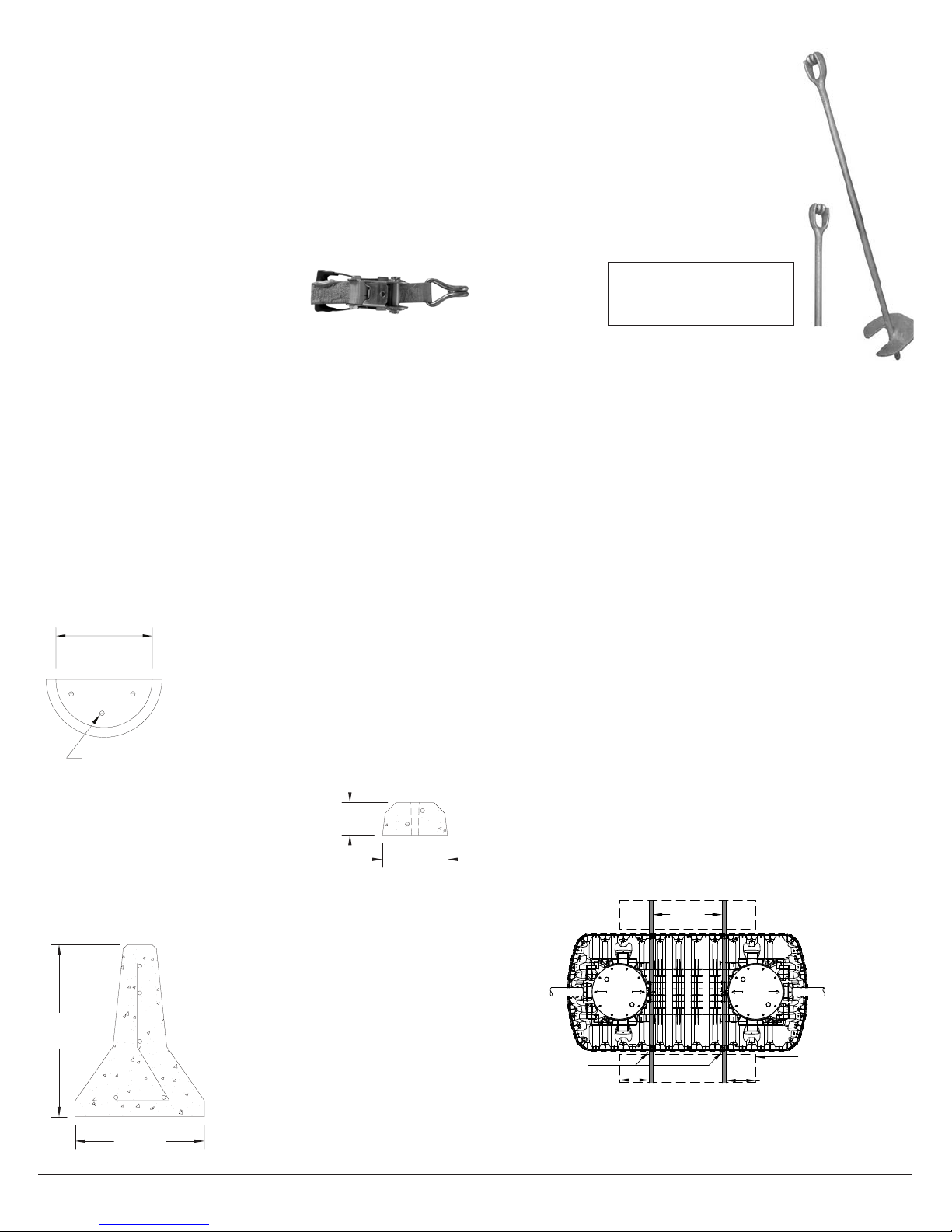
Tie-Down Straps
Straps are commercially available in varying
lengths and with assorted hardware and
tightening options. Nylon or polyester
strapping with minimum 10,000 lb (4,500 kg)
capacity is required for buoyancy control use
with Infiltrator tanks. Place straps over the tank at specified locations only
(see Figure 5). Tighten straps snugly with a ratchet or turnbuckle system to
remove all slack and slightly pre-load the system. All connections, fittings,
and hardware must be corrosion resistant or coated with epoxy or other
corrosion-resistant materials to inhibit deterioration in the subsurface
environment. Consider encapsulating such components in heat-shrink
tubing or applying a corrosion-resistant coating prior to burial.
Concrete Deadmen Anchors
Recommended concrete deadmen anchors include filled plastic half pipe,
precast parking bumpers and traffic barriers, and precast blocks. The
weight of the deadmen anchors combined with the weight of soil above
them provides buoyancy control when properly secured. Deadmen anchors
are placed at the bottom of the tank excavation on opposite sides of the
tank. The deadmen anchors are fastened to each other with tie-down
straps placed over the tank at the locations specified for each tank model
(see Figure 5).
Concrete-filled Plastic Half Pipe
Use Schedule 40 PVC plastic pipe with a minimum
inside diameter of 15 inches (375 mm) or HDPE
corrugated pipe with a minimum inside diameter of
18 inches (450 mm) cut in half lengthwise. Fill with
concrete having a minimum unit weight of 145 lbs/ft3
(2.32 metric tons/m3) reinforced with three equally
spaced 40-grade,
1/2-inch (13 mm) diameter steel bars. Weight is 61
lbs/ft (91 kg/m) minimum.
Concrete Parking Bumper
Use commercially available steel-reinforced
parking bumpers with typical dimensions of 12
inches wide by 6 inches high (300 mm x 150 mm).
Weight is 58 lbs/foot (86 kg/m) minimum.
Concrete Traffic Barrier
Use commercially available steel-reinforced concrete traffic barrier or
equivalent. Typical dimensions include a
24-inch-wide base tapering to a 6-inch-
wide top, with a height of approximately
32 inches (600 mm x 150 mm x 800 mm).
Weight is 390 lbs/foot (580 kg/m) minimum.
Precast Blocks
Concrete precasters can fabricate blocks
of various dimensions and weights. Blocks
are often an affordable option if they satisfy
the minimum weight requirements for use
as buoyancy control (see Table 2 and the
Supplemental Force section of Step 2 for
more information).
Helical Anchors
Chance™ No-Wrench Screw Anchors with a
6-inch (150 mm) diameter flight, Class 7, or
equal. These anchors rely on the shear strength
of the soil combined with the weight of the
soil above the anchor flight to provide holding
strength. Proper installation is to 4 feet (1.2 m)
below the bottom of the tank excavation and to
within 5° of alignment with the strap alignment.
Determine the proper locations for anchor
installation to ensure that tie-down straps will
be aligned properly for each tank model (see
Step 3: Implementation), and follow the anchor
manufacturer installation instructions.
Concrete Collar
A ballast may be constructed along the mid-
height seam of the tank using cast-in-place concrete (minimum 3,000
psi compressive strength at 28 days and minimum 6% air entrainment).
Concrete shall be cast in contact with the exterior surface of the tank to
allow interlock with sidewall ribs and the mid-height flange. Reinforcing
steel is not required, but may be added if desired.
Step 3 – Implementation
Effective buoyancy control of Infiltrator tanks requires careful preparation,
thorough excavation, precise placement, secure strapping and proper
backfilling, as described and illustrated below.
Excavation Requirements
It is recommended that the excavation width provide a minimum of 36
inches (900 mm) clearance beyond the tank on all sides when utilizing
buoyancy control. This will allow sufficient space within the excavation to
place anchoring equipment and fasten strapping. The excavation should
provide a minimum 48-inch (1,200 mm) clearance beyond the tank when
using Chance™ No-Wrench Screw Anchors to allow for room to properly
install the screw anchors. The actual excavation size shall be determined by
the installer. Refer to Infiltrator IM-Series Tank Installation Instructions for
additional excavation procedures.
Concrete-filled Half Pipe Construction
Concrete-filled half pipe shall be supported with soil or other stabilizing
means below the pipe haunches prior to concrete placement. The
stabilization shall prevent the pipe from rolling during placement and curing
of the concrete. Concrete shall be allowed to cure for a minimum of one
day prior to tank backfilling.
Placement of Deadmen and Anchors
Concrete deadman anchors are to be installed at the bottom of the tank
excavation, parallel to the long axis of the tank (see Figure 3).
Figure 3: Plan View
The deadmen should be placed close to, but not touching, the tank on both
sides of the tank to allow the placement of backfill between the deadman
anchor and tank sidewall (see Figure 4).
18 in
[450mm]
12 in
[300 mm]
6 in
[150 mm]
24 in
[600 mm]
32 in
[800 mm]
Quick4 Plus Equalizer 36 LP
Typical working torque:
¾” Rod 400 ft. lbs. (542 N•m)
1” Rod 1,000 ft. lbs. (1,356 N•m)
1¼” Rod 2,300 ft. lbs. (3,118 N•m)
15 in [375 mm] to
18 in [450 mm]
Steel Rebar
18 in
[450mm]
12 in
[300 mm]
6 in
[150 mm]
24 in
[600 mm]
32 in
[800 mm]
Quick4 Plus Equalizer 36 LP
STRAPPING
DEADMAN
ANCHOR
(TYPICAL)
STRAP
WIDTH
6" (150 mm)
MIN EXTENSION
6" (150 mm)
MIN EXTENSION
Contact Infiltrator Water Technologies’ Technical Services Department for assistance at 1-800-221-4436.
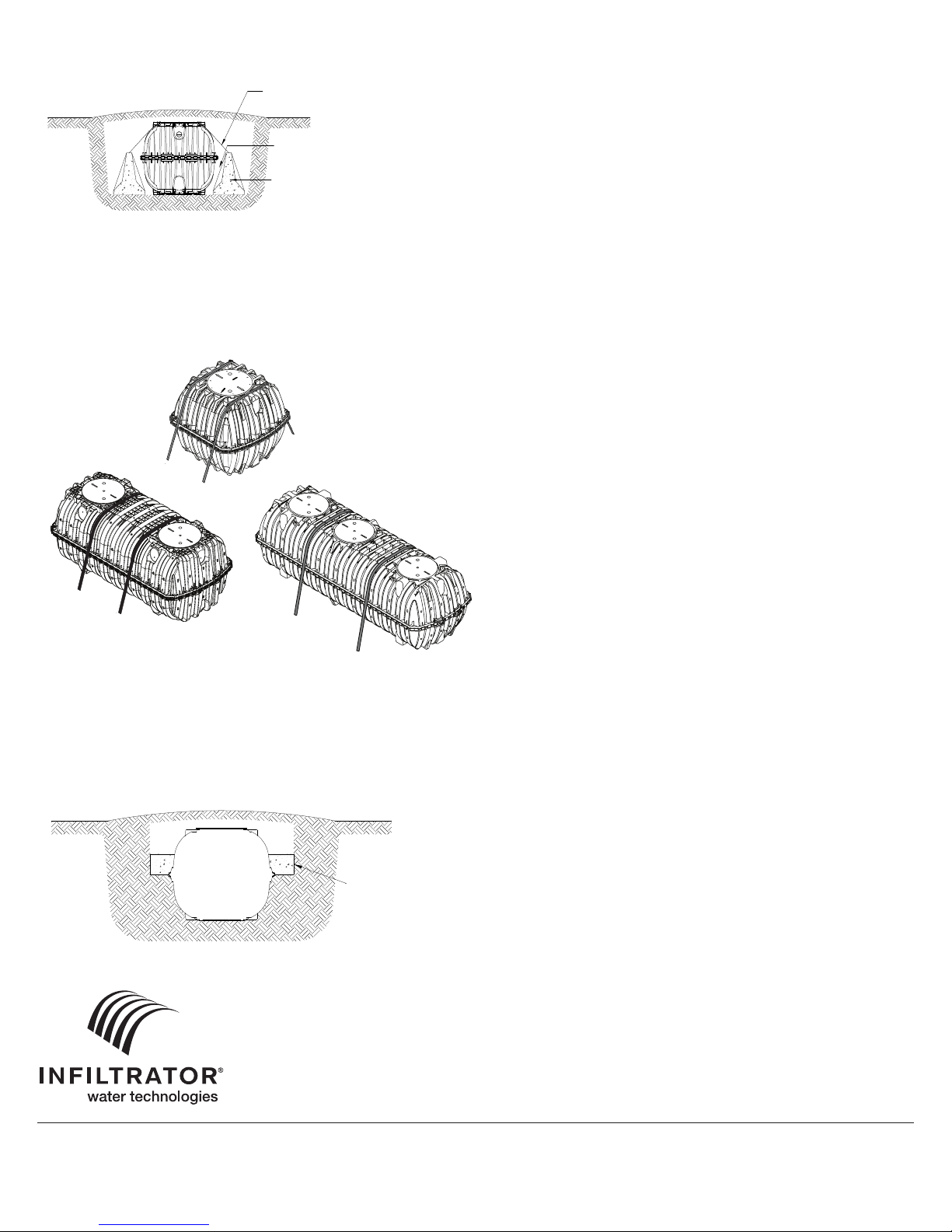
Strapping
Proper installation of straps over the tank is critical for tank stability under
constant and fluctuating water conditions both inside and outside the tank.
Straps must be placed at the specified strapping locations for each model,
as illustrated in Figure 5. Strapping locations are embossed on the exterior
surface of the tank with the following text: “SHIPPING /ANTI-BUOYANCY
STRAP HERE.” The IM-Series tank strapping locations correspond to
structurally reinforced areas of the tank body. Straps must never be placed
over access openings, lids, or inlet/outlet piping. Straps must be tightened
with a ratchet or turnbuckle system to remove slack and slightly pre-load
the system.
STRAPPING NOTES:
1. The buoyancy control shall be centered across the straps (excludes
helical anchors). The control shall extend a minimum of 6 inches (150 mm)
beyond the maximum strap width (see Figures 3 and 5).
2
.
The minimum deadman length corresponds to the tank model-specific strap
width plus 12 inches (300 mm).
Backfill and Cover
Place backfill between deadman anchor and tank sidewall to fully fill void
and tank body corrugations. A minimum 6” layer (150 mm) of suitable cover
material is required over all Infiltrator tank installations. Mound cover to
direct surface water drainage away from the tank excavation footprint to
prevent filling of the tank excavation with precipitation. Establish erosion-
resistant vegetation within the tank installation footprint. Refer to Infiltrator
IM-Series Tank Installation Instructions for complete backfilling and cover
procedures.
General Specifications
• Prior to ground disturbance, check for subsurface obstructions and
utilities in conformance with applicable regulatory requirements.
• Excavation safety provisions shall conform to applicable government
regulations.
• Follow manufacturer instructions for all products and devices used for
Infiltrator tank buoyancy control.
• Buoyancy control methods described herein do not account for
unanticipated conditions such as surface flooding, temporary inundation
or other natural occurrences, unintended removal of cover fill over tank,
etc.
• Buoyancy control methods described herein are recommendations only;
consult a professional engineer for customized designs, if desired.
Parts and Supplies
The parts and supplies necessary are to be purchased separately from the
tank. All parts and supplies are either commercially available or available
through Infiltrator’s network of tank distributors. Some parts may require
fabrication on site using common construction practices.
4 Business Park Road
P.O. Box 768
Old Saybrook, CT 06475
860-577-7000 • Fax 860-577-7001
1-800-221- 4436
www.infiltratorwater.com
U.S. Patents: 4,759,661; 5,017,041; 5,156,488; 5,336,017; 5,401,116; 5,401,459; 5,511,903; 5,716,163; 5,588,778; 5,839,844 Canadian Patents: 1,329,959; 2,004,564 Other patents pending. Infiltrator, Equalizer, Quick4,
and SideWinder are registered trademarks of Infiltrator Water Technologies. Infiltrator is a registered trademark in France. Infiltrator Water Technologies is a registered trademark in Mexico. Contour, MicroLeaching,
PolyTuff, ChamberSpacer, MultiPort, PosiLock, QuickCut, QuickPlay, SnapLock and StraightLock are trademarks of Infiltrator Water Technologies. PolyLok is a trademark of PolyLok, Inc. TUF-TITE is a registered
trademark of TUF-TITE, INC. Ultra-Rib is a trademark of IPEX Inc.
© 2016 Infiltrator Water Technologies, LLC All rights reserved. Printed in U.S.A.
Figure 4: Section View
Helical anchors should be installed so that the eye loop is level with the
bottom of the tank excavation. They must be in line with the tank model
strapping locations (see Figure 5) or lifting lugs, as appropriate. Anchors
must also be installed at such a distance from and angle to the tank so that
the strapping is within 5° of alignment with the anchor shaft per the anchor
manufacturer’s recommendations.
Figure 5: Strap Positioning
Concrete Collar
Backfill the tank to the mid-seam area. Concrete (minimum 3,000 psi at 28
days and minimum 6% air entrainment) shall be cast in contact with the
exterior surface of the tank to allow interlock with sidewall ribs and the mid-
height flange. The bottom of the concrete collar shall be cast at the top of
the mid-seam flange.
TANK03 1016
33"
(838 mm)
38"
(965 mm)
63"
(1,600 mm)
IM-1530
IM-540
IM-1060
PROVIDE ADEQUATE SPACE FOR
BACKFILL PLACEMENT BETWEEN
DEADMAN ANCHOR AND TANK
STRAPPING (TYPICAL)
DEADMAN ANCHOR
CONCRETE COLLAR
SECTION VIEW
This manual suits for next models
3
Popular Water Heater manuals by other brands


Bradford White
Bradford White Combi2 "CDW2" Series Replacement parts list

Rheem
Rheem STID30 instruction manual

Ariston
Ariston 45 Assembly and operation instructions
 Installation & operating instructions")
A.O. Smith
A.O. Smith BTH 120-250(A) Installation & operating instructions

Morco
Morco EUP11 User, installation, and maintenance manual

Regent
Regent THERMODYNAMIQUE ECO manual


