3. INSTALLATION
3.a Regulations
The use of gas devices is controlled by precise regulations.
Installation of liquified petroleum gas (L.P.G) must comply with all
the manufacturer’s requirements and those of the regulations.
3.b Wall mounting
Warning
Do not install this device in an area that contains dust, greasy
vapour and/or corrosive elements.
- The device must be installed on a suitable wall surface that
allows the fitting of a vertical exhaust gas flue
- It is vital to leave the minimal distances around the device as
shown in fig 4 to allow for maintenance operations to take place.
Location
The water heater requires a plentiful supply of fresh air for correct
operation. Fixed ventilators or air inlets should not be obstructed.
Do not install the water heater in a location where incomplete
combustion is foreseeable such as bathrooms or bedrooms unless
specifically allowed by national legislation.
The minimum low and high level free ventilation areas are stated
on this page and must be observed.
The water heater must be fixed to a load bearing wall in a vertical
plane.
3.c Room ventilation
The installation of the water heater must comply with regulations in
force including any updates. See page 3
Warning: This device can only be installed in venues that are
permanently ventilated according to regulation in force.
• COMBUSTION GAS REMOVAL
A single wall vertical flue pipe of Ø110mm must be used and when
it passes through combustible materials, a metal sleeve of
Ø170mm must be used to allow an air gap of 25 mm. Part code
FTFCTG101.
Flue pipes and terminals should comply with BS 715. Terminals
shall not be sited within 300 mm. of a ventilator or open window. In
the U.K. full details of flueing requirements are given in BS EN 1949.
The overall length of the flue must be 600mm from the bottom of
the terminal louvres to the top of the water heater. At least 250mm
of this length must be external to the roof through which it is fitted.
• AIR SUPPLY FOR COMBUSTION
Air requirements: Reference is made to BS 5482 (BS EN 1949) and
EN 721 covering ventilation requirements for permanent dwellings,
caravans and boats.
Fixed ventilation should be provided to avoid draughts as far as
possible without impairing the free area of ventilation, even in ad-
verse weather conditions. If the heater is positioned in location
which may be subjected to strong draughts i.e. close to a window
or opening then strong draughts or gusts of wind may extinguish the
pilot.
All permanent openings for ventilation should be designed to pre-
vent the entry of vermin. Where screens are provided, they should
not have apertures of less than 6 mm. or greater than 9 mm. in any
direction, and they should be accessible for cleaning. Fine mesh screens
shall be avoided as they are liable to become blocked with dust.
The location of vents and the method of cleaning them should be
stated in the Owners Handbook (Caravans and Boats).
As a guide, the minimum effective free area of vents is stated below
in connection with this water heater. Additional appliances burning
gas in the same area would require additional ventilation.
If the appliance is installed in an enclosed cupboard in a Caravan
Holiday Home the required ventilation is that specified in BS 5482
part 2 and BS EN 1949, i.e. 10 cm² per kilowatt input rating divided
between high and low. Each of the high and low vents should
therefore be 109 cm² of free area.
3.d Gas Connection
The water heater should be connected to the gas supply via a
15mm diameter copper gas pipe. A gas isolation valve must be fit-
ted to the gas inlet on the water heater.
When installing or commissioning the water heater the following
must be observed:
- The diameter of the gas pipe between the supply bottle or tank
must be in accordance with the regulations in force
- The regulator size and pressure specification are correct for the
application
- The correct gas (LPG) is being supplied
- All the required gas pressure and tightness tests are carried out
as part of the commissioning process.
- Gas joints downstream of the magnetic gas valve must be
checked with leak detection fluid while the heater is running
- Gas jointing paste should not be used when connecting the gas
isolation valve
Do not obstruct the area’s ventilation openings where the device is
installed to avoid dangers such as the build-up of toxic and explosive
gases.
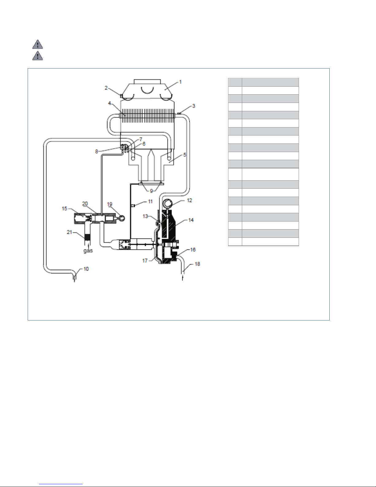
ATTENTION: if the appliance is supplied with G31@50 mbar,
remove the protective cap (pos. 10 water heater components pag.
7) and regulate the pressure screw so that the burner reaches the
pressure indicate in the technical data.


 Operation and maintenance instructions")