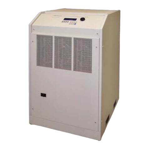
Infinite Transtector 700 A/VS Series User manual

Series 700 A/VS Power Conditioner
110K(i) Power Conditioner with
Voltage Regulation (50 Hz)
Owners Manual
Dual Output Power Conditioner
with Voltage Regulation
110K(i) 50 Hz Model Front Access Design
Important safety instructions - save these instructions and review prior to using equipment
▪111711 Rev 5

110K(i) 50 Hz Power Conditioner | Owners Manual 2
TABLE OF CONTENTS
Receiving and Inspecting the Unit 3
General Description 4
Safety Precautions 5
Preliminary Installation 6-7
Weights, BTU and Dimensions 7
Input Wire Size, Grounding and Output Wiring 8-9
Installation 10-13
Bypass Switch 14
Start - up 15
Preventive Maintenance 16
Performance Checklist 17
General Troubleshooting 18
Parts List 19
Warranty 20
APPENDIX A 21
Cabinet Layout 22-24
Seismic Calculations 25
Symbol Library 26
Notes 27

3
1402-001
RECEIVING & INSPECTING THE UNIT
INSPECTING THE POWER PROCESSOR
Upon receipt of the unit, visually inspect for shipping damage. If any damage is found, the Purchaser
must contact the Carrier immediately and le a shipping damage claim.
NOTE: Be sure to remove the front and side panels, and inspect the inside of the unit for shipping damage.
If any internal damage has occurred or any external damage that could affect the operation of the unit,
please contact Transtector.
FOR ASSISTANCE CALL 1-800-882-9110 X 6112 (8am-5pm Pacic Time)
AFTER HOURS CALL 1-800-521-4792
STORING
If it is necessary to store the unit for a period of time before it is installed, be sure to place the unit in a
clean, dry area. To prevent excessive dust from accumulating on the unit, it is advisable to protect it by
replacing it in the original container (if possible). If the original container is not available it is recommended
that all openings that lead internally into the unit are covered so that dust, water or any other substance
cannot enter the internal components of the system. The unit must be handled at all times with the same
care you would give to any piece of precision industrial equipment.
REMOVING THE POWER PROCESSOR FROM PALLET
Please take special care when removing the unit from the pallet. Proper equipment must be used for
lifting and moving, and all safety precautions should be taken. Each unit is bolted to a wooden pallet.
In order to properly remove the cabinet from the pallet, all bolts connecting the unit to the pallet must be
removed completely. The unit can then be lifted off the skid using a pallet jack or a fork lift, as shown
below. When lifting the unit off of the pallet, be sure to take proper safety precautions. Serious injury and/
or unit damage can result otherwise.

110K(i) 50 Hz Power Conditioner | Owners Manual 4
GENERAL DESCRIPTION
The Series 700 A/VS Power Processor is designed to supply reliable, clean regulated power to critical
loads. An efcient design with state of the art micro-processor controlled solid state devices provide
immunity to all line disturbances.
The basic design consists of a three phase triple shielded isolation transformer with seven separate voltage
taps per phase. Output regulation is achieved by monitoring the input and automatically switching taps
anytime the input line sags or surges. The use of a triple shielded isolation transformer provides superior
common mode and transverse mode noise attenuation. Automatic switching occurs during current zero
allowing noise free switches for both leading and lagging power factor loads that are connected to the
Series 700A/VS.
MONITOR
Monitoring of the Series 700A/VS is simple, clean and effective. Three green light indicators are utilized
to display “POWER ON” (output line to neutral for each phase) and one red light indicator to display
“ALERT”. The “POWER ON” display is connected directly to the output that indicates the Series 700A/
VS is operating properly with just a quick glance. The “ALERT” display represents an over-temp problem
or output voltage loss (optional) when illuminated, and will shut down the output, but cooling fans remain
on. Over-temp thermal sensors are strategically located at critical points on the regulator assemblies
and transformer. The main AC input circuit breaker must be turned off in order to reset the “ALERT” light.
PROTECTION
Protection is accomplished very effectively to minimize failures and the cost of repairs. A total of ve major
devices protect the Series 700A/VS.
1. The input is protected with a integrally mounted AC circuit breaker for abnormal current overloads and
provides a convenient means of disconnecting utility power.
A. As an option the input breaker may be equipped with a shunt trip device that is interfaced with a
REMOTE EMERGENCY POWER OFF PUSH BUTTON. By pressing this button, the input breaker
will trip and disable the Series 700A/VS completely. The input breaker must be physically reset
before unit will turn on again.
2. The main transformer is protected by fuse links connecting the SCR regulators together, and are
designed to clear in the event that two or more SCR’s should fail. This will prevent a transformer tap
short and the possibility of transformer failure.
3. (Optional) The output of the Series 700A/VS is constantly monitored for extreme over and under
voltage conditions. This device monitors each output phase and will electronically disable the Series
700A/VS when any phase exceeds +10% or -10% of nominal output voltage.
4. Overtemp sensing devices are mounted at critical points on the SCR regulating assembly and the
main transformer. When an overtemp condition exists the “ALERT” light will illuminate and hold until
the overtemp is corrected. There are no automatic shut-off circuits for the “ALERT” condition. The
main AC input breaker must be turned off in order to reset the “ALERT” light.

5
1402-001
**** WARNING ****
THERE ARE DANGEROUSLY HIGH VOLTAGES PRESENT WITHIN THE
ENCLOSURE OF THE POWER SUPPLY SYSTEM.
CAUTION MUST BE TAKEN WHEN WORKING WITH THE SYSTEM.
IT IS RECOMMENDED THAT ALL WORK BE PERFORMED BY QUALIFIED
ELECTRICAL PERSONNEL ONLY.
SAFETY PRECAUTIONS
**** CAUTION ****
RISK OF ELECTRICAL SHOCK AND HIGH SHORT CIRCUIT CURRENT.
THE FOLLOWING PRECAUTIONS SHOULD BE OBSERVED
WHEN WORKING ON THE UNIT:
1) REmOvE wATChES, RINgS, OR OThER mETAL ObjECTS.
2) USE TOOLS wITh INSULATEd hANdLES.
3) wEAR RUbbER gLOvES ANd bOOTS.
**** CAUTION ****
- FOLLOW ALL STANDARD AND LOCAL ELECTRICAL CODES.
- dO NOT ALLOw wATER OR FOREIgN ObjECTS TO gET INSIdE ThE UNIT.
- dO NOT PLACE ObjECTS OR LIqUIdS ON TOP OF ThE UNIT.
- DO NOT LOCATE THE UNIT NEAR RUNNING WATER.

110K(i) 50 Hz Power Conditioner | Owners Manual 6
PRELIMINARY INSTALLATION
INSTALLATION CONSIDERATIONS
Prior to installing the Series 700A/VS, be sure to take into consideration the site you have selected. Power
Conditioners produce heat and therefore require ventilation as well as accessibility. Consider these factors.
CHOICE OF LOCATION
The unit has been completely inspected and extensively tested under various load conditions prior to
shipment. Care to install it at a proper location will assure long trouble-free operation.
The unit is air cooled with the air intake at the front and exhausts at the top. Therefore, it should be installed
in a clean, dry place with enough clearance to allow a free ow of air. Allow a minimum of 36” in front of
the 700A/VS for installation, operation, and maintenance. There is no clearance required on either the
left or right hand side of this enclosure. Either or both sides, as well as the rear of the enclosure, can be
set ush up against a wall. Input and output conductors should then enter/exit via the top and/or bottom
of the enclosure as indicated.
▪Ventilation ▪Input Source Voltage
▪Size of the Power Conditioner ▪Receiving Facilities
▪Weight Load ▪Distribution of Power
▪Audible Noise Requirements ▪Room Temperature
▪Remote Emergency Power Off (Repo) ▪Clearances
▪Monitors ▪Accessibility
▪Options ▪Excessively Long Power Runs
▪Clean Environment ▪Proper Ground Techniques
TOP VIEW
FRONT
NO CLEARANCE REQUIRED
NO CLEARANCE REQUIRED
NO CLEARANCE REQUIRED

7
1402-001
**** CAUTION ****
INPUT AND OUTPUT BREAKER SIZE
OUTPUT KVA OUTPUT KVA
CONTINUOUS
INPUT
BREAKER SIZE
OUTPUT BREAKER SIZE MAX OUTPUT CURRENT
110 K(I) 50 kVA 175A @ 380 V
175A @ 400 V
175A @ 415 V
Output #1 - 80 A, 3P for 400/230V
Output #2 - 60 A, 3P for 400/230V
Output #1 65A Continuous Rating
Output #2 65A Momentary Rating
for 30 seconds @ 4.2%
duty cycle
UNIT SIZE IN KVA (I) WEIGHT OPERATIONAL BTU/
HR TYPICAL
MAXIMUM
BTU/HR
DIMENSIONS
110 K(I) 1,254 lbs.
568.8 kg.
3,410* 6,820 29” W x 35.875” D x 66.0” H
(73.6 cm. x 91.1 cm. x 167.6 cm.)
* Stated BTU’s / Hr is at 100% rated load, 100% duty cycle. Operational BTU’s / Hr is typically at 65% of rated
load.

110K(i) 50 Hz Power Conditioner | Owners Manual 8
Refer to the latest edition of The National Electric Code Requirements for
over-current protection and wire sizing.
INPUT WIRE SIZE, GROUNDING AND OUTPUT WIRING
A. Conduit should be used for both input and output wiring.
B. Input wire size is based on the NEC table 310.16. Specifying not more than 3 connections in a raceway
based on an ambient of 30°C and wire rated for 90°C (Note: amperages will need to be adjusted for
40° C ambient applications).
C. Input phase conductors are terminated directly to the input circuit breaker terminals.
Wire range:
380 VAC 175 Amp breaker #4 AWG to 350 KCMIL (25mm2to 150mm2)
400 VAC 175 Amp breaker #4 AWG to 350 KCMIL (25mm2to 150mm2)
415 VAC 175 Amp breaker #4 AWG to 350 KCMIL (25mm2to 150mm2)
D. Input ground lug TA-250, max wire range 6 AWG - 250 MCM.
E. Output is a 4 wire (5 including ground). If four (4) current carrying conductors are used in a raceway
the neutral is assumed to be current carrying and the wire must be de-rated as indicated in table 310.6
on the NEC.
Example: 1. Assume #10 wire max current = 25 Amps.
2. Multiply 25 x .8 = 20
3. 20 Amps is max current for #10 wire in a raceway with 4 conductors.
NOTE: Installation is subject to local codes - verify with a local electrical inspector.
F. All output ground and neutral terminals are PK9 grounding bar with a TA 2/0 lug.
PK9 wire range #14 AWG to #4 AWG. TA 2/0 lug wire range #14 AWG to 2/0AWG.
Output connections are made directly to the output breaker(s) and the output neutral and ground bus
provided. The load current is not to exceed 80% of the output breaker(s) rating, and not to exceed
the rated total current.
Output wiring sizes:
400/230 VAC 80 Amp breaker #14 AWG to 1/0 (2.5mm2to 50mm2)
400/230 VAC 60 Amp breaker #14 AWG to 1/0 (2.5mm2to 50mm2)
G. Output neutral to ground bonded during manufacturing of the power conditioner. Output Neutral is
already grounded by the factory.
H. Installation is subject to local codes. Verify with a local electrician inspector.

9
1402-001
INPUT WIRE SIZE, GROUNDING AND OUTPUT WIRING (continued)
common

110K(i) 50 Hz Power Conditioner | Owners Manual 10
INSTALLATION
CABINET OUTLINE - FRONT VIEW
63.000"
66.000"
AIR
INLET
FRONT VIEW
160.02 cm
167.64 cm

11
1402-001
INSTALLATION (continued)
CABINET OUTLINE - TOP AND BOTTOM VIEW
BOTTOM VIEW
TOP VIEW
36" CLEARANCE REQUIRED FOR SERVICING
NO CLEARANCE REQUIRED IN BACK OF UNIT
NO CLEARANCE REQUIRED ON LEFT SIDE OF UNIT
OPTIONAL 12" CLEARANCE ON RIGHT SIDE OF UNIT
(IF USING OPTIONAL SIDE OUTPUT TERMINATION)
NO CLEARANCE REQUIRED ON LEFT SIDE OF UNIT
OPTIONAL 12" CLEARANCE ON RIGHT SIDE OF UNIT
(IF USING OPTIONAL SIDE OUTPUT TERMINATION)
3.875
24.750
2.125
Ø 0.562
30.750
2.562 2.292
6.895
8.000
3.8748.000
3.187
6.895
35.875
29.000
BOTTOM
INPUT/OUTPUT
LOCATION
TOP INPUT/OUTPUT
LOCATION
AIR
OUTLET
91.12 cm
73.66 cm
17.51 cm
8.09 cm
20.32 cm 9.84 cm
5.39 cm
6.51 cm
78.10 cm
62.96 cm
5.82 cm
9.84 cm
17.51 cm
20.32 cm
1.43 cm

110K(i) 50 Hz Power Conditioner | Owners Manual 12
INSTALLATION (continued)
CABINET OUTLINE - RIGHT SIDE VIEW
NO CLEARANCE
REQUIRED IN BACK
OF UNIT
NO CLEARANCE REQUIRED ON RIGHT OR LEFT SIDES OF UNIT
OPTIONAL 12" CLEARANCE ON RIGHT SIDE OF UNIT (IF USING OPTIONAL SIDE OUTPUT TERMINATION)
4.5002.812
4.750
8.250
OPTIONAL SIDE
OUTPUT TERMINATION
ACCESS AREA
RIGHT SIDE
AIR FLOW
20.96 cm
12.06 cm
7.14 cm 11.43 cm

13
1402-001
INSTALLATION (continued)
INPUT AND OUTPUT CONNECTIONS
1. Input connections are made directly to the unit’s 3 pole main input circuit breaker and input ground
lug provided. Note the bottom access wire run route illustrated below.
2. Output connections are made directly to the output breaker(s) and output neutral and ground bus
provided. The load current is not to exceed 80% of the output breaker(s) rating, and not to exceed
the rated total current.
63.000
66.000
TVSS
(MOUNTED TO MID-PANEL)
BYPASS SWITCH
MONITOR ALERT LIGHTS
INPUT BREAKER
(CUSTOMER'S INPUT
CONNECTS TO TOP)
AIR
INLET
FRONT VIEW
80A
400V
OUTPUT
BREAKER
60A
400V
OUTPUT
BREAKER
TVSS
BREAKER
167.64 cm
160.02 cm
NEUTRAL & GROUND OUTPUT
TERMINALS CONSIST OF
PK9 GROUNDING BAR
WIRE: 14 AWG. - 4 AWG.
& TA 2/0 LUG
WIRE: 14 AWG - 2/0 (2.5mm
2
- 50mm
2
)
(2.5mm
2
- 25mm
2
)

110K(i) 50 Hz Power Conditioner | Owners Manual 14
BYPASS SWITCH
**** CAUTION ****
Prior to switching from one position to another- turn off the AC input breaker.
The manual bypass switch is a break before make switch located on the Series 700A/VS. The manual
bypass switch is used to bypass all power electronics in case of failure.
NORMAL MODE
With the switch in the normal position, the Series 700A/VS will provide clean and regulated power to the
critical loads. The Series 700A/VS should have the switch in the normal position unless a failure has
occurred.
BYPASS MODE
With the switch in the bypass position, the Series 700A/VS will provide clean power to the critical loads.
In the bypass position, the unit will not regulate the incoming voltage. The Series 700A/VS should be
placed in the bypass position when a failure of the system has occurred. This provides the user with some
protection until a service technician arrives.
REMOTE EMERGENCY POWER OFF (REPO) OPTION
The REPO is operated by a remote push button that when depressed will shunt trip the Series 700A/VS
input breaker and disable the unit. This option may be added to units in the eld.
Contact the Customer Support Department if you wish to add this option.

15
1402-001
START UP
NOTE: INITIAL START-UP SHOULD BE PERFORMED WITH NO LOAD ON SYSTEM.
1. Re-install all panels that may have been removed during installation.
2. Make sure the input circuit breaker is in the off position.
3. Energize the primary building power.
4. Turn on the main AC input breaker.
5. Verify that the output voltage is within the specied range.
6. Verify output phase rotation is correct.
7. Turn the system off.
8. Connect the loads one at a time and repeat Step 4.
**** WARNING ****
THERE ARE DANGEROUSLY HIGH VOLTAGES PRESENT WITHIN THE ENCLOSURE OF
THE POWER SUPPLY SYSTEM. CAUTION MUST BE TAKEN WHEN WORKING WITH
THE ENCLOSURE. IT IS RECOMMENDED THAT ALL WORK BE PERFORMED BY
QUALIFIED ELECTRICAL PERSONNEL ONLY.

110K(i) 50 Hz Power Conditioner | Owners Manual 16
**** WARNING ****
dANgER OF ELECTRICAL ShOCK, TURN OFF ALL POwER SUPPLYINg ThIS EqUIPmENT
PRIOR TO MAINTENANCE.
To ensure longer component life and trouble-free operation, minor preventive maintenance procedures
should be performed at regular intervals, for example once every year. More frequent inspection intervals
would be needed for more severe operating conditions and larger number of hours of continuous operation.
1. Remove front and side panels and at each service inspection any accumulated dust, dirt or foreign
particles should be carefully removed. Special care should be exercised in cleaning the thyristors
(SCR’s), heat sinks and the control assembly.
2. Inverse Parallel Silicon Rectiers (SCR’s) or Thyristors - The silicon controlled rectiers (SCR’s or
Power Mods) usually fail in the shorted mode. When this happens, normally the fusible link in series
with the SCR will be blown open to clear the short and prevent damage to the transformers. If a blown
SCR is suspected, contact Transtector for service.
3. A simple performance checklist has been developed for use in maintenance. See “Performance
Checklist” and check off items 1-7.
4. After items 1-7 have been checked on the “Performance Checklist”, the next step is to check the
operation of the system.
5. Replace front and side panels. Turn unit on with no load. Check item 8 on the “Performance Checklist”
6. Turn on loads and check items 9-10 off the “Performance Checklist”.
7. Check to make sure all fans are operational and check off item 11.
NOTE: Preventive Maintenance Plans are available. Please contact the Customer Support Group for
information. Call 1-800-882-9110 X6112.
PREVENTIVE MAINTENANCE
Rick Ribbeck
Phone: (O) 208-635-6400 Ext. 5867 | (M) 208-762-6112
E-mail: [email protected]
E-mail: [email protected]
Transtector Systems
10701 Airport Dr.
Hayden Lake ID 83835
SERVICE
Transtector shall provide immediate phone support/consultation and if possible, same day parts shipment.
(contact must be prior to 12:00 PM PST). If necessary, on site service shall be scheduled the same day
for service to be conducted within 24 to 48 hours, based on customer requirements. Typical service hours
are 8 AM to 5 PM Monday through Friday.

17
1402-001
PERFORMANCE CHECKLIST
Company______________________________________________________________
Model #____________________________Serial #__________________
1. Customer Comments or Problems____________________________________
2. Power Processor Environment Clean and Dust Free Yes_______ No________
3. Phase Rotation Correct (ABC) Yes_______ No________
4. Electrically wired properly ie...Conductor Sizing, Breakers, Grounding
5. Verify Input Voltage (See specication tag)
6. Check Tightness of Electrical Connections:
______Input Connections______Output Connections______Heatsink Connections (SCR’s)
______Circuit Board Connections______By-Pass Switch______Fuse Connections
______Fan Connections______Transformer Connections
7. Exercise all circuit breakers-
______Input Breaker______Output Breakers
8. Input/Output Voltage Checks (Adjust as Needed).
No Load Input No Load Output
A-B__________VAC__________ A-N__________VAC A-B__________VAC
B-C__________VAC__________ B-N__________VAC B-C__________VAC
A-C__________VAC__________ C-N__________VAC A-C__________VAC
9. Available Load Input Available Load Output
A-B__________VAC__________ A-N__________VAC A-B__________VAC
B-C__________VAC__________ B-N__________VAC B-C__________VAC
A-C__________VAC__________ C-N__________VAC A-C__________VAC
10. Input/Output Current Checks (Balance as Needed).
Input Output
A__________Amps A__________Amps
B__________Amps B__________Amps
C__________Amps C__________Amps
N__________Amps
G__________Amps
11. Fans Operational_________________________________________________________

110K(i) 50 Hz Power Conditioner | Owners Manual 18
GENERAL TROUBLESHOOTING
SYMPTOM PROBABLE CAUSES
1. No Output on One or More Phases. A. No Input.
B. Blown Fuse.
C. Defective SCR or Power Mod.
D. Defective Control Card.
E. Defective Sense Card.
2. Output is too High or too Low. A. Input Out of Range.
B. Control Card Adjustment.
C. Defective Control Card.
D. Defective Sense Card.
E. Defective SCR or Power Mod.
3. Input Breaker Tripping Off. A. System Overloaded.
B. Defective Breaker.
C. Shorted Taps.
**** WARNING ****
THERE ARE DANGEROUSLY HIGH VOLTAGES PRESENT WITHIN THE
ENCLOSURE OF THE POWER SUPPLY SYSTEM. CAUTION MUST BE TAKEN WHEN
WORKING WITH THE ENCLOSURE. IT IS RECOMMENDED THAT ALL WORK BE
PERFORMED BY QUALIFIED ELECTRICAL PERSONNEL ONLY.
Rick Ribbeck
Phone: (O) 208-635-6400 Ext. 5867 | (M) 208-762-6112
E-mail: [email protected]
E-mail: [email protected]
Transtector Systems
10701 Airport Dr.
Hayden Lake ID 83835
SERVICE
Transtector shall provide immediate phone support/consultation and if possible, same day parts shipment.
(contact must be prior to 12:00 PM PST). If necessary, on site service shall be scheduled the same day
for service to be conducted within 24 to 48 hours, based on customer requirements. Typical service hours
are 8 AM to 5 PM Monday through Friday.

19
1402-001
PARTS LIST
QTY 380 V INPUT 400 V INPUT 415 V INPUT DESCRIPTION
PART #
1 204382 204382 204382 MAIN TRANSFORMER
1 104034 104034 104034 MAIN INPUT BREAKER
6 17694 17694 17694 FILTER CAPACITOR
6 16777 16777 16777 FILTER RESISTOR
2 19149 19149 19149 CONTROL FUSE (3A)
1 110366 110366 110366 CONTROL TRANSFORMER
3 16638 16638 16638 SENSE FUSE (.75A)
1 13789 13789 13789 CONTROL RELAY
1 13696 13696 13696 PILOT LIGHT - RED
3 203943 203943 203943 SENSE BOARD
3 25723 25723 25723 SNUBBER BOARD
3 419721 419721 419721 MAIN CONTROL BOARD
3 108888 108888 108888 PILOT LIGHT - GREEN
1 100810 100810 100810 BYPASS SWITCH
1 104023 104023 104023 80A, OUTPUT BREAKER
1 104145 104145 104145 60A, OUTPUT BREAKER
1 104310 104310 104310 30A, TVSS BREAKER
1 110844 110844 110844 TVSS
21 109906 109906 109906 POWER MODULE (SCR)
3 13319 13319 13319 THERMAL SENSOR
6 104607 104607 104607 FUSIBLE LINK
3 104561 104561 104561 DIODE
3 103759 103759 103759 BLOWER MOTOR

110K(i) 50 Hz Power Conditioner | Owners Manual 20
WARRANTY
WARRANTY VALIDATION
WARRANTY VOID UNLESS THIS FORM IS COMPLETE AND
RETURNED TO TRANSTECTOR SYSTEMS
Transtector Systems, Inc. warrants that the Series 700 A/VS Power Conditioner and its components will remain free from
defects in material and workmanship for the period of two (2) years from the date of shipment and agrees to replace F.O.B.
its factory, any part or parts which fail through defect in material or workmanship during such period.
▪The Warranty shall be effective only if and so long as the system is installed and operated in the manner specied
in the manual which accompanied the Power Conditioner and operated within the ratings on the nameplate of the
system.
▪The Warranty shall be void if any alteration is made to the system or any of its components are altered by anyone
other than authorized personnel.
▪The cost of transporting a questionable component and/or a replacement component to and from the factory is the
responsibility of the customer. The expense of installation of the replacement component is the responsibility of the
purchaser, unless covered by the GOLD PLAN or GOLD PLUS PLAN. Factory servicemen are not included in this
warranty.
▪This Warranty is in lieu of all other warranties, expressed or implied. The giving of, or failure to adhere to any advice
or recommendations by Transtector Systems shall not constitute any warranty by, or impose any liability upon the
company. Transtector Systems Inc. neither assumes nor authorizes any person to assume for it, any liability other
than that specically set forth in this Warranty. Except for its obligations, Transtector Systems, Inc. assumes no
responsibility for consequential or other damages resulting from defects in workmanship or failure of the system or
any components.
▪This warranty does not apply if the cause of the failure to properly perform is re, ood, windstorm, earthquake,
misuse, or abuse or any other reason other than those described above, i.e. defects in manufacture. If the component
fault has been caused by misuse or abnormal conditions in the judgment of factory personnel after inspection at our
plant, the customer will be charged for repairs based on parts and labor required.
Model #
Date
Title
Start up Organization
Serial #
Company
Address
City/State/Zip
Contact
Phone
Complete and return form to:
Attn: Rick Ribbeck
Transtector Systems, Inc.
10701 Airport Dr.
Hayden Lake ID 83835
Phone 208-635-6400 Ext. 5867
Fax 208-762-6133
Table of contents
