Infinity BassLink+4 User manual

BassLink+4
™
BassLink+4
™
i
n
s
t
r
u
c
t
i
o
n
s

2
INTRODUCTION
THANK YOU for choosing the Infinity BassLink+4™
System Upgrade Solution. BassLink+4 has
been designed to provide the kind of high
performance that used to require big, clumsy
enclosures, large amplifiers and complex
installation. To ensure maximum performance,
we strongly recommend that installation be
entrusted to a qualified professional. Although
these instructions explain how to install the
BassLink+4 in a general sense, they do not
show the specific installation methods for your
particular vehicle. If you feel you do not have
the necessary tools or experience, do not
attempt the installation yourself; rather, ask
your authorized Infinity car audio dealer about
professional installation options. Remember to
keep this manual and your sales receipt in a safe
place for future reference.
HEARING WARNING!
Playing loud music in a vehicle can permanently
damage your hearing, as well as hinder your
ability to hear traffic. We recommend using
low volume levels while driving. Infinity accepts
no liability for hearing loss, bodily injury or
property damage resulting from the use or
misuse of this product.
PARTS LIST
(1) Powered subwoofer
(2) Mounting feet
(4) 3mm x 18mm Screws to attach
mounting feet to sub
(4) #8 x 1" Screws to attach feet to vehicle
(1) 5m Phone cable
(1) Remote bass level/phantom control
(2) #6 x 3/4" Screw to hold remote control
(2) 5m Speaker input cables
(2) 5m RCA input cables
(1) 35 Amp fuse
(1) 25 Amp fuse
(1) Phantom setup CD
(1) Owner’s manual
(1) Warranty card
CHOOSING A MOUNTING LOCATION
Choose a mounting location that doesn’t interfere
with cargo, fold-down rear seats or the trunk lid.
The best location is usually a corner of the trunk
or cargo area, as shown in Figures 1 and 2.
These locations, in addition to being out of the
way, will provide the best sonic reproduction in
the 60Hz to 100Hz range because the woofer
output will be “corner loaded”against the
vehicle’s walls. In any case, BassLink+4 must not
interfere with the safe operation of the vehicle.
Figure 1. BassLink+4 in a car’s trunk.
Figure 2. BassLink+4 in an SUV’scargo area.
CAUTION: Make sure mounting screws will not
puncture wiring harnesses, brake or fuel lines, or
the vehicle’s fuel tank. Some or all of these may
be located behind or under the mounting surface.
VERTICAL MOUNTING
Position BassLink+4 so that the heatsink is facing
down and the bottom of the unit is up. Align the
mounting feet as shown in Figure 3. Secure the
feet using the supplied machine screws.
Note: Place BassLink+4 (with its feet) so the
controls are easy to adjust.
Securely mount BassLink+4 to the mounting
surface with the four enclosed self-tapping screws.
Figure 3. Vertical mounting of BassLink+4.
HORIZONTAL MOUNTING
Position BassLink+4 so that the controls are
facing down and the back of the unit is up. Align
the mounting feet as shown in Figure 4. Secure
the feet using the supplied machine screws.
Note: Place BassLink+4 (with its feet) so the
controls are easy to adjust.
Securely mount BassLink+4 to the mounting
surface using the four enclosed self-tapping screws.
Figure 4. Horizontal mounting of BassLink+4.
MOUNTING BASSLINK+4

BassLink+4
3
UNDER-DASH MOUNTING
Select a mounting location that allows easy
access to the control while driving. Using the
REMOTE LEVEL control as a template, mark and
drill holes in the mounting surface. Attach the
REMOTE LEVEL control using the mounting
screws provided (Figure 5).
Figure 5.Under-dash mounting of the REMOTE
LEVEL control.
Route the cable behind the dash or other interior
panels and under the carpet. Do not route the
cable outside the vehicle. Connect the RJ11 cable
between the RJ11 receptacle on the BassLink+4
and the receptacle on the REMOTE LEVEL control
(Figure 6).
Figure 6.REMOTE LEVEL control electrical
connection.
INSTALLING THE REMOTE CONTROL
Make Power, Ground and Remote Turn-On
connections as shown in Figure 7. Observe
the following installation tips:
•Connect a short #8AWG GND wire from
Basslink+4 to the nearest bare metal surface.
Scrape away paint from the metal surface, if
necessary, and use a screw with a (star) lock
washer.
•Install a fuse holder with a 60A fuse within 18"
of the battery + terminal (see Figure 7).
•Use #8 AWG wire for the +BATT (+12Vdc) and
GND (ground) connections. If needed, use at
least a #20 AWG wire for the REM (remote)
connection.
•If you pass the power or remote wire through
the vehicle’s firewall or other metal obstruction,
it must be insulated with a rubber grommet.
•If your head unit provides a remote turn-on
lead, connect it to the REM terminal on
BassLink+4. For speaker-level applications,
aremote connection is not required, since
BassLink+4’s Auto Turn On feature will sense
asignal on the speaker wires and turn on
automatically.
Figure 7. Power connections for BassLink+4.
IMPORTANT: To enable BassLink+4’s Auto
Turn On feature, set AUTOTURN ON to the
AUTO position (see Figure 12 on page 5).
POWER CONNECTIONS

4
Note: In order for the Phantom Center circuit to
operate properly, the speakers and input wires
MUST be connected in proper polarity!
SPEAKER CONNECTIONS
Connect the speakers to the FRONT and REAR screw
terminals, observing proper polarity (Figure 8).
Figure 8. BassLink+4 audio connections.
INPUT CONNECTIONS
BassLink+4 is equipped with four line-level
(RCA) inputs and four speaker-level inputs. Any
combination of line-level and speaker-level inputs
may be used to provide nonfading bass when
connected to a head unit with four outputs.You
must provide a full-range signal to all four input
channels. Do not connect a subwoofer output to
any of the inputs.
Connect the input signal wires according to
Figures 8a through 8d.
If your source unit provides only speaker-level
output wires, connect those wires to the Universal
Interface connections as shown in Figures 8a or 8b.
If your source unit provides line-level outputs with
RCA-type connectors, connect the signal cables to
the FRONT and REAR LINE LEVEL inputs as shown
in Figure 8c or 8d.
If your source unit provides two line-level outputs
and two speaker-level outputs, you may connect
the line-level output to the appropriate (front or
rear) RCA-type input and the speaker-level
outputs to the other (front or rear) Universal
Interface connector.
Remote Level
Control
4-Channel
Line-Level Outputs
(from Source Unit)
Remote Level Control
LF
LR
RR
RF
Source Unit
Remote Level
Control
Remote Level
Control
Remote Level
Control
2-Channel
Line-Level Outputs
(from Source Unit)
2-Channel Speaker Outputs
(from Source Unit)
4-Channel Speaker Outputs
(from Source Unit)
Rear
Front
Figure 8a: Input connections for a radio with four speaker level outputs
Figure 8b: Input connections for a radio with two speaker level outputs
Figure8c: Input connections for a radio
with four RCA connections
Figure8d: Input connections for a radio
with two RCA connections (use “y” adapters)
CONNECTIONS

CONTROLS AND FUNCTIONS
REMOTE CONTROL
SUB LEVEL: Use this control to adjust the
amount of bass to suit your preference.
PHANTOM CENTER:
LEFT: Slide the switch to this position to provide
aphantom center for front left seating position.
OFF: Slide the switch to this position to turn off
Phantom Center processing.
RIGHT: Slide the switch to this position to provide
aphantom center for front right seating position.
Note: Once you have chosen the best Phantom
Center switch position and made the necessary
adjustments to the Front Gain and Rear Gain
controls and set the Subwoofer Level control
and Phase switch, you won’t need to make any
further adjustments.
BASSLINK+4 SIDE-PANEL
PHANTOM CENTER: Use this switch to select the
proper adjustment of the Phantom Center circuit
according to your car and your preference, using
the setup CD.
FRONT/REAR GAIN: Use these to adjust the levels
of the front and rear speakers.
POWER LED:This indicator will glow blue when
BassLink+4 is operational.
Figure 11.BassLink+4 front-panel controls.
POWER LED: This indicator will glow blue when
BassLink+4 is operational.
GAIN CONTROL: Use this control to adjust the
relative volume (loudness) of BassLink+4’s
subwoofer with respect to the other speakers
in the vehicle.
CROSSOVER: Use this control to adjust the
amount of high-frequency information present
in BassLink+4’s subwoofer speaker.
BASS BOOST: Use this control to correct any
perceived peak or dip in the bass response
(typically around 40Hz in most vehicles). Set the
control to any value between –6dB and +3dB,
according to your preference.
Figure 12.
PHASE CONTROL: Use this switch to invert
the phase of BassLink+4’s subwoofer output.
AUTO TURN ON: For speaker-level connections,
use this switch to activate (or deactivate)
BassLink+4’s automatic turn-on circuit.
SERVO LED: This indicator glows blue when the
subwoofer is at maximum excursion and the
amplifier is modifying the output to maintain
maximum performance.
BassLink+4
5
Figure 9.REMOTE LEVEL controls. Figure 10.BassLink+4 side-panel controls.

TUNING BASSLINK+4
6
SETTING THE FRONT SPEAKER AND
SUBWOOFER LEVELS
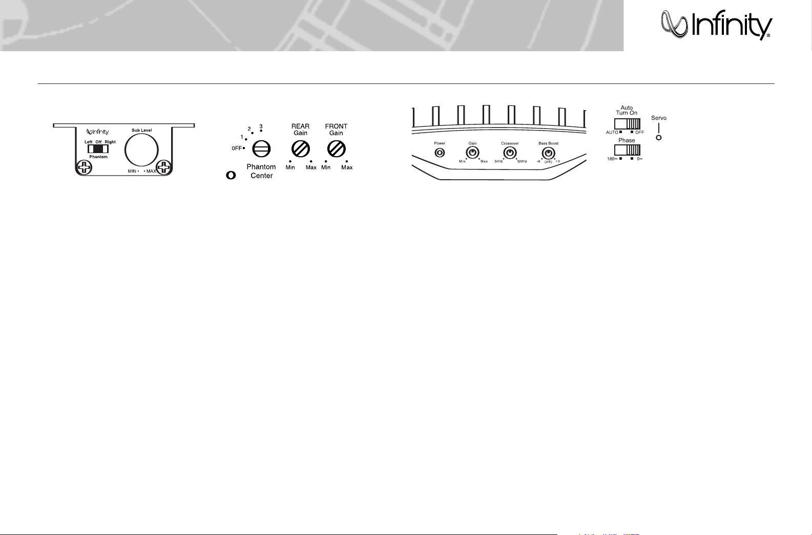
Note: Refer to page 5, ”Controls and Functions,”
for the location of controls.
1. Turn on the audio system and verify (using
the Balance and Fader controls) that the
speakers and input channels are connected
properly – when the Balance control is turned
to the left, only the left speakers should
play, and when the control is turned to the
right, only the right speakers should play.
BassLink+4’s subwoofer should play regardless
of the Fader or Balance control’s position.
2. Turn the Rear Gain (located on BassLink+4’s
end panel) and BassLink+4’s subwoofer Gain
control (located on BassLink+4’s front panel)
all the way down. Turn the Front Gain
(located on the BassLink+4’s end panel) to
1/4 volume. Only the front speakers should
be playing. Additionally, turn BassLink+4’s
Crossover control and Bass Boost control to
their midpoint positions and set BassLink+4’s
phase control to the 0° position.
3. Play a dynamic music track with substantial
bass content – Track 5 or 9 on the Phantom
Center Setup CD is suitable – and turn the
source unit’s volume control to 3/4 volume.
4. Turn the Front Gain control up until you
hear slight distortion in the music (fuzzy
or crackling sounds). Then reduce the Front
Gain control slightly until the distortion is
no longer present.
5. Turn the Sub Level control (on the remote
level control) to its maximum output setting
(fully clockwise).
6. While listening to the same track that you
used in Step 3, turn BassLink+4’s Gain control
clockwise until the servo light (located on
BassLink+4’s end panel) begins to flash with
each bass note but doesn’t stay lit continuously.
7. While sitting in the driver’s seat, listen to
your system, making a mental note of the
amount of upper bass being reproduced.
8. Switch the Phase control to the 180° position
and listen again for upper bass content.
There may be more upper bass, less upper
bass or there may be no change. The position
that provides the most upper bass is correct,
but choose either setting according to your
preference.
9. Adjust the Crossover control until you hear
only low-frequency information coming from
BassLink+4’s woofer. You should use the
highest (clockwise) position possible that
doesn’t allow any vocal information to be
audible from BassLink+4’s woofer (when you
listen in the driver’s position).
10. Adjust the Bass Boost control clockwise or
counterclockwise to suit your preference.
ABOUT THE PHANTOM CENTER CIRCUIT
Note: In order for the Phantom Center to work
properly, the front speakers MUST be connected
in correct polarity. Additionally, some factory-
installed audio systems use extensive and
nondefeatable equalization and channel delay,
which may diminish the effect of the Phantom
Center circuit.
The Phantom Center circuit provides four
tuning selections: Off, 1, 2 and 3. These settings
process the audio signal differently and provide
optimization for several different car sizes and
front speaker mounting locations. The chart
below indicates switch positions that will
probably sound best for a variety of car sizes
and speaker locations, but there is no correct
setting.You should choose the one you like best.
Note: The Phantom Center circuit affects the
midrange speaker only in switch position 1,
but may affect the separate tweeter, as well,
in switch positions 2 and 3, depending on the
tweeter’s cutoff frequency. If you have separate
tweeters mounted in the tops of the doors or
in the dashboard, and the chart indicates two
possible switch positions, the second position
may be the better choice.
Using the Phantom Center Setup CD, you’ll listen
to some instructions, a spoken setup track and
several music selections to determine the best
adjustment for your system. The first four tracks
are spoken tracks, withTrack 3 being the most
important of those tracks. Portions of Track 3
have been recorded through the equivalent of
the Phantom Center circuit. Listen to Track 3,
“Spoken Setup Track”,and choose the switch
position that provides the best illusion of a person
speaking halfway between the front speakers.
Track 3:
0:00-0:10 Switch in the Off position
0:11-0:21 Switch position 1
0:22-0:33 Switch position 2
0:34-0:47 Switch position 3
0:48-0:60 Rapid switching between
the three positions
Tracks 5 through 16 are music tracks. There
are three excerpts of songs and each excerpt
is recorded four times; once with no processing
(switch in the Off position), once through switch
position 1, once through switch position 2 and
once through switch position 3. Using the music
tracks, choose the switch position that distributes
the sound best between the right and left speakers.
You can use the following list of tracks as a guide.
PHANTOM CENTER SETUP CD
Track 1 Introduction
Track 2 Instructions for Track 3
Track 3 Spoken Setup Track
Track 4 Instructions for Music Tracks
Track 5 Lonely Savior (no processing)
Track 6 Lonely Savior (switch position 1)
Track 7 Lonely Savior (switch position 2)
Track 8 Lonely Savior (switch position 3)
Track 9 Another Time, Another Place
(no processing)
Track 10 Another Time, Another Place
(switch position 1)
Track 11 Another Time, Another Place
(switch position 2)
Track 12 Another Time, Another Place
(switch position 3)
Track 13 Cinderella’s Revelation
(no processing)
Track 14 Cinderella’s Revelation
(switch position 1)
Track 15 Cinderella’s Revelation
(switch position 2)
Track 16 Cinderella’s Revelation
(switch position 3)
Track 17 Conclusion
Track 18 Lonely Savior: Ken Birmingham
Track 19 Another Time, Another Place:
MikeChristian
Track20 Cinderella’s Revelation: Joe Chinnici
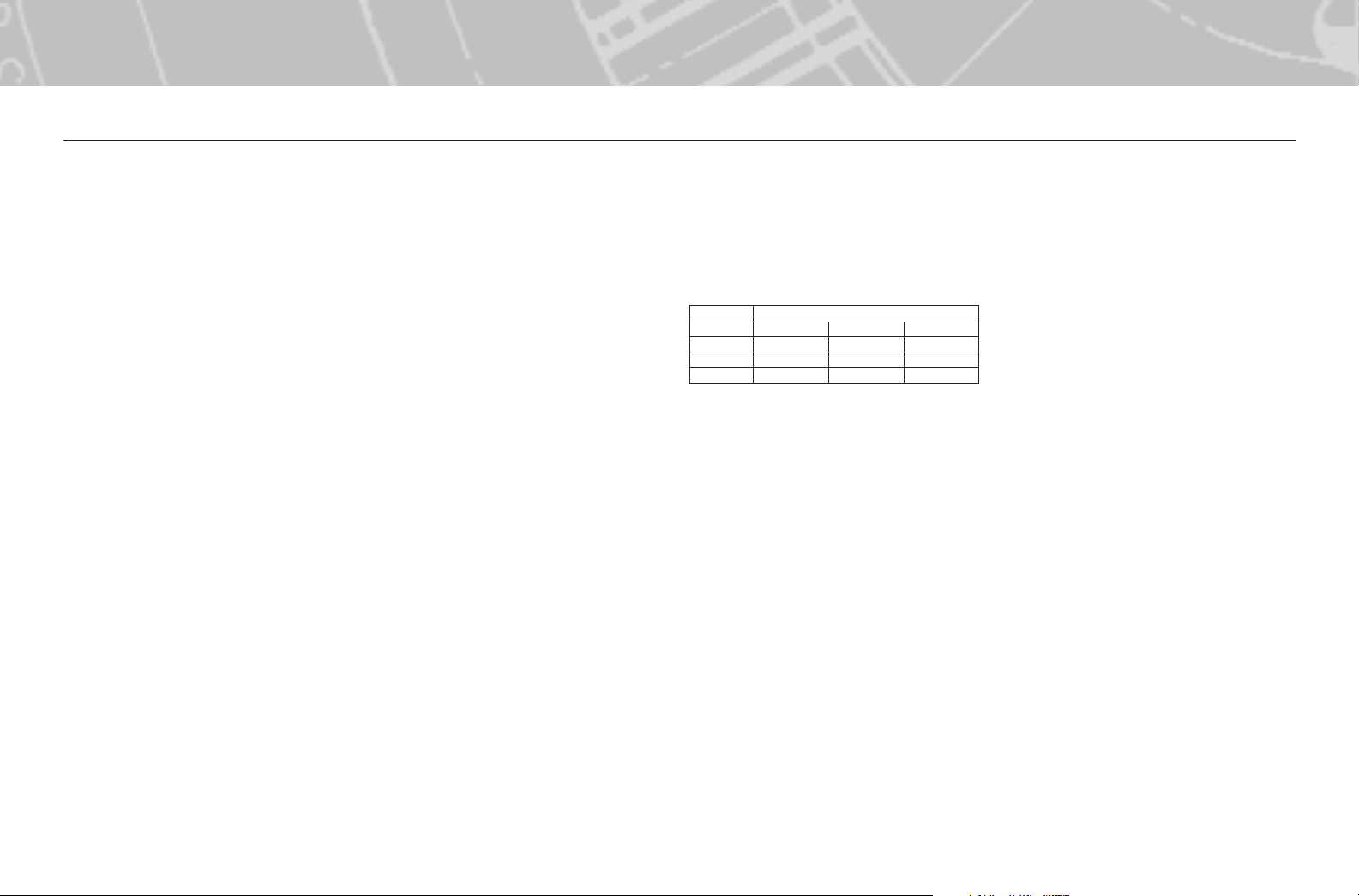
Midrange Speaker Location
car size doors dash kick panel
small 2 2 or 3 3
mid-size 1 or 2 2 or 3 3
large 1 2 2 or 3

TROUBLESHOOTING
BassLink+4
7
TUNING BASSLINK+4 (CONT.)
SETTING THE PHANTOM CENTER CIRCUIT
1. Before you begin, set the Phantom switch on
the remote control for the seat in which you
are sitting. Set the Phantom Center switch on
the BassLink+4 to the Off position.Turn the
Rear Gain control on the BassLink+4 all the
way down (counterclockwise) and make sure
no sound is coming from the rear speakers.
2. Insert the Phantom Center Setup CD into your
CD player.
3. Follow the spoken instructions on the setup CD.
4. Once you have chosen the switch position you
like best using Tracks 1–17, stop the CD and
move the Phantom Center switch on the
BassLink+4 to the position you have chosen.
You can use Track 17 and the music selections
that follow (Tracks 18–20) to check your work.
ADDING THE SOUND FROM THE REAR
SPEAKERS
With music playing, turn the Rear Gain control
clockwise until sound from the rear speakers is
clearly audible but not so loud that it makes the
music seem to come from the back of the car.
• PROBLEM:
Power LEDs are not lit.
CAUSES and SOLUTIONS:
1. Poor or improper power connection. Check
power, ground and remote connections.
Check speaker level input for proper
connections (see No Output).
2. Blown or improperly installed fuse.
Check main battery fuse and replace
if necessary.
Check fuses on BassLink+4.
• PROBLEM:
Power LEDs are lit, but there is no sound from
one or all speakers.
CAUSES and SOLUTIONS:
1. Improper input signal connections. Check
all input connections on BassLink+4 and
source unit.
2. Damaged speaker wire or improper speaker
connections. Check speakers and wiring;
change if necessary.
3. Improper signal connections on BassLink+4.
Check gray ribbon signal cable connection
to BassLink+4 (see Figures 8a, 8b, 8c and 8d).
• PROBLEM:
BassLink+4 sounds muddy or distorted.
CAUSES and SOLUTIONS:
1. Gain is set too high and SERVO LED is lit
constantly. Readjust GAIN control (see Tuning
BassLink+4 on page 6).
2. Bass is set too high. Readjust BASS BOOST
control (see Tuning BassLink+4 on page 6).
3. Head-unit output is distorted or blown. See
your authorized Infinity car audio dealer.
• PROBLEM:
No output from BassLink+4.
CAUSE and SOLUTION:
Input connections are improperly wired. Verify
all connections (see Figures 8a, 8b, 8c and 8d).
• PROBLEM:
No output from BassLink+4 when head-unit
fader control is set to front or rear (in a
4-channel connection).
CAUSE and SOLUTION:
Input connections are improperly wired.
Verify all connections (see Power
Connections,on page 3).
• PROBLEM:
BassLink+4 turns on before head unit is
completely on and produces a “thump”
sound.
CAUSE and SOLUTION:
For speaker-level connections, head unit is
producing a false turn-on signal. On BassLink+4’s
side panel, slide AUTO TURN ON to OFF. It will
be necessary to connect the Remote lead
to a switched ignition voltage source.
• PROBLEM:
BassLink+4’s POWER LED remains on after
head unit is turned off.
CAUSE and SOLUTION:
For speaker-level connections, this is normal
operation when AUTO TURN ON is set to ON.
BassLink+4 will remain on for another 5 to 10
minutes after sensing that audio signals are not
present before shutting down.

Declaration of Conformity
We, Harman Consumer Group International
2, route de Tours
72500 Château du Loir
France
declare in own responsibility that the product described in this owner’s
manual is in compliance with technical standards:
EN 55013:2001+A1:2003
EN 55020:2002+A1:2003
Klaus Lebherz
Harman Consumer Group International
Château du Loir, France 7/06
SPECIFICATIONS
BassLink+4™
Subwoofer
Amplifier Power: 250W RMS
Frequency Response: 20Hz to 120Hz
Fuse: 25A
Max. Current Draw: 26A
Idle Current Draw: < 800mA
Input Sensitivity: 50mV to 4V Line-level input
1V to 16V universal interface
Crossover Frequency: 50Hz to 120Hz
Crossover Slope: 12dB per octave
Bass Boost: –6dB to +3dB @ 40Hz
Dimensions (L x W x H): 15-1/16" x 8-3/4" x 15-5/16"
(383mm x 223mm x 389mm)
Sub Level Control 2-3/16" x 2-5/16" x 7/8"
(with housing): (56mm x 59mm x 23mm)
Sub Level Control 2-3/16" x 1-5/16" x 3/4"
(without housing): (56mm x 34mm x 20mm)
High-Frequency
Amplifier Power: 35W x 4 channels at 4 ohms
50W x 4 channels at 2 ohms
Frequency Response: 90Hz to 47kHz
Fuse: 30A
Max. Current Draw: 26A
Idle Current Draw: <800mA
Input Sensitivity: 100mV to 6V line-level input
1V to 16V universal interface
Crossover Frequency: Fixed 80Hz high-pass
Crossover Slope: 12dB per octave
Infinity Systems, 250 Crossways Park Drive, Woodbury, NY 11797 USA
516.674.4463 (USA only) • www.infinitysystems.com
©2006 Harman International Industries, Incorporated. All rights reserved.• Part No. BASSLINK+4OM7/06
Infinity and Harman International are trademarks of Harman International Industries, Incorporated, registered in the United States and/or other countries.
BassLink+4 is a trademark of Harman International Industries, Incorporated.
A valid serial number is required for warranty coverage.
Features, specifications and appearance are subject to change without notice.
This product is designed for mobile applications and is not intended for connection to the mains.
Table of contents
Other Infinity Car Stereo System manuals
Popular Car Stereo System manuals by other brands

JVC
JVC KD-DV4202 Installation & connection manual

JVC
JVC KW-XC828T Installation and connection manual

Sony
Sony XS-GTR1720 Specifications

Metra Electronics
Metra Electronics 95-3003G installation instructions

Roadstar
Roadstar CD-302MP/FM Service manual

JL Audio
JL Audio Stealthbox SB-F-SUPRCC/13TW5 installation guide