manuals.online logo
Brands
  1. Home
  2. •
  3. Brands
  4. •
  5. Infinity
  6. •
  7. Car Stereo System
  8. •
  9. Infinity kappa series User manual

Infinity kappa series User manual

Subwoofer Owner's Manual
KAPPA 1200w
KAPPA 1000w
KAPPA 800w
KAPPA SUBWOOFERS
THANK YOUfor choosing a Infinity
Kappa subwoofer. These subwoofers
are designed to suit a broad range of car
audio applications and can be used in a
wide variety of enclosure types to produce
extended, powerful bass in a limited
amount of vehicle space. To get the most
performance from your new subwoofer, it
is strongly recommended that you have a
qualified professional install your
subwoofer. Although this manual does
provide general instructions about
installing these Kappa subwoofers, it does
not include enclosure construction details
or exact installation methods for any
particular vehicle. If you do not feel that
you have the necessary experience, do not
attempt the installation yourself, but
instead ask your authorized Infinity dealer
about professional installation options.
Remember to keep your sales receipt in a
safe place, along with this manual, so
that both are available for future
reference.
WARNING
Playing loud music in a vehicle can hinder
your ability to hear traffic and
permanently damage your hearing. The
maximum volume levels achievable by Infinity
speakers when combined with high-power
amplification may exceed safe levels for
extended listening. Using low volume
levels is recommended when driving. Infinity,
Inc. accepts no liability for hearing loss,
bodily injury, or property damage as a
result of use or misuse of this product.
REPRODUCING
BASS IN VEHICLES
Depending on the size of your vehicle’s
interior listening space, reproduced bass
frequencies below 80Hz will be boosted
by nearly 12dB per octave as frequency
decreases. This phenomenon, known as
the vehicle’s transfer function (or cabin
gain), plays an important role in shaping
the subwoofer’s frequency response in
your vehicle.
SUBWOOFER
ENCLOSURE TYPES
The subwoofers are designed to perform
best in moderately sized sealed
enclosures, vented enclosures and
prefabricated band-pass enclosures.
Infinite-baffle mounting is possible, but
the subwoofer’s mechanical power
handling will be reduced because there
will be no volume of air to stiffen the
subwoofer’s suspension and prevent
overexcursion. If you choose infinite-baf-
fle mounting, consider the RMS and peak
power-handling ratings to be half of what
is listed in the specifications in this
manual.
You should choose an enclosure type
based on the amount of cargo space you
can devote to the enclosure, the amount
of power you will use to drive your
subwoofer(s), and your listening habits.
handling at and above resonance, but
reduced mechanical power handling below
resonance. Since the subwoofer cone and
voice coil don’t move much at resonance,
airflow across the voice coil is minimized
and thermal power handling is reduced
slightly at resonance.
Vented enclosures provide better
efficiency in the 40Hz – 60Hz range, at
the expense of sound output in the lowest
octave (below 40Hz). The use of an
infrasonic filter is recommended with
vented enclosures. An optimum vented
enclosure for a Kappa subwoofer is larger
than an optimum sealed enclosure.
VENTED-ENCLOSURE PERFORMANCE
ADVANTAGES
• An optimum vented enclosure has
greater efficiency and higher output in
the 40Hz – 60Hz range than an optimum
sealed enclosure.
• An optimum vented enclosure provides a
greater sensation of bass than an
optimum sealed enclosure.
• A subwoofer in an optimum vented
enclosure will require less amplifier
power to achieve a given acoustic
output (down to the enclosure’s
resonance frequency) than in an
optimum sealed enclosure.
VENTED-ENCLOSURE PERFORMANCE
TRADE-OFFS
• Reduced output in the lowest octave
(below 40Hz).
• Reduced mechanical power handling
below the enclosure’s resonance
frequency. The use of an electronic
infrasonic filter is strongly recommend-
ed to reduce the chance of overdriving
the subwoofer below the enclosure’s
resonance frequency.
• An optimum vented enclosure will
always be larger than an optimum
sealed enclosure.
VENTED-ENCLOSURE CONSTRUCTION
Vented-enclosure construction is more
difficult than the construction of a sealed
enclosure. The enclosure volume and port
dimensions have a specific relationship
with the physical and electromechanical
characteristics of the subwoofer,
requiring that the recommended
enclosure volume and port characteris-
tics be strictly observed. As with sealed
enclosures, use medium-density
fiberboard (MDF), glue and screws to
construct the enclosure, and seal all
joints with silicone caulk.
RECOMMENDATION
Subwoofers in vented enclosures are
recommended for enthusiasts who prefer
accentuated bass response, for those who
have plenty of cargo space to devote to a
subwoofer enclosure and for those who
will use a less powerful amplifier to drive
their subwoofer. The volume and port
dimensions indicated must be followed
precisely to ensure optimum
performance.
MOUNTING THE
SUBWOOFER
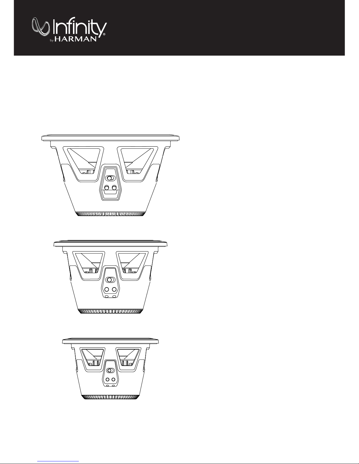
The subwoofers should be
mounted from the outside of the
enclosure. Use the included foam
mounting gasket to ensure a leak-free
seal between the subwoofer frame and
the enclosure.
CONNECTING THE
SUBWOOFER
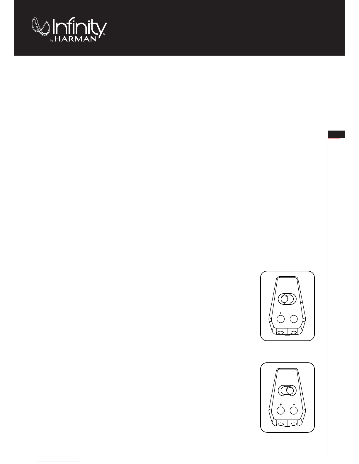
SETTINGTHE IMPEDANCE
The Kappa subwoofers both feature
the Selectable Smart Impedance™
(SSI) switch.This exclusive feature lets
you set the subwoofer’s impedance to
either 2 ohms or 4 ohms with the flip of a
switch (see illustrations below).This
allows you to extract the most from your
subwoofer amplifier in any situation.
The SSI 2-ohm setting increases the
subwoofer’s output over the 4-ohm
setting by up to 3dB,depending on the
amplifier.Performance is identical in all
other respects. If the connected amplifier
is rated for 2-ohm operation and its 2-ohm
power ratings are within the subwoofer’s
power-handling specifications, setting
the SSI switch in the 2-ohm position will
achieve maximum output.
SEALED ENCLOSURES
The air trapped inside a sealed enclosure
is compressed when the subwoofer moves
rearward and is rarefied when the
subwoofer moves forward. In both cases,
the air inside and outside the box will
seek equilibrium by pushing and pulling on
the subwoofer cone. The result is a
stiffer suspension when compared to the
subwoofer operating in free air. This
means that the subwoofer’s cone will be
harder to move at low frequencies, a
condition which protects the subwoofer
from physical overexcursion, but
requires more power than other designs
to achieve a given acoustic output.
SEALED-ENCLOSURE PERFORMANCE
ADVANTAGES
•The in-vehicle performance will have
the flattest overall frequency response.
•The in-vehicle response will have the
widest bandwidth. (Usable low-frequency
response inside the vehicle will be
below 20Hz.)
•An optimum sealed enclosure will always
be smaller than an optimum enclosure of
another type.
SEALED-ENCLOSURE PERFORMANCE
TRADE-OFFS
•An optimum sealed enclosure will have
lower overall efficiency than an
optimum enclosure of another type.
•A subwoofer in an
optimum sealed enclosure will require
more amplifier power to achieve a given
acoustic output than in an optimum
enclosure of another type.
SEALED-ENCLOSURE CONSTRUCTION
Sealed-enclosure construction is straight-
forward and forgiving of errors in volume
calculation, but air leaks should be
avoided. Use medium-density fiberboard
(MDF), glue and screws to construct the
enclosure, and seal all joints with silicone
caulk.
RECOMMENDATION
Subwoofers in sealed enclosures are
recommended for enthusiasts who prefer
accurate music reproduction and flat
frequency response, for those who have a
smaller space to devote to a subwoofer
enclosure, and for those who have plenty
of amplifier power devoted to driving the
subwoofer. The sealed-enclosure design
indicated in this manual represents the
best compromise between low-frequency
extension and flat response.
VENTED ENCLOSURES
A vented enclosure acts like a sealed
enclosure at frequencies above its tuned
(resonance) frequency. At resonance
(which is defined by the vent), the vent
produces the majority of sound – the
subwoofer cone is nearly stationary while
the air inside the vent vibrates. This
provides greater mechanical power
2-Ohm Setting
4-Ohm Setting
KAPPA SUBWOOFERS
4Ω2Ω
4Ω2Ω
EN
Kappa 800w/Kappa 1000w Kappa 1200w
TECHNICAL DATA
KAPPA 800W
T
HIELE
-S
MALL
P
ARAMETERS 2
Ω
4
Ω
V
OICE
-C
OIL
DC R
ESISTANCE:
R
EVC
(
OHMS
) . . . . . . . . 2.005. . . . . . . . . . 3.941
V
OICE
-C
OIL
I
NDUCTANCE
@ 1
K
Hz: L
EVC
(
M
H) .......... 1.10........... 0.85
D
RIVER
R
ADIATING
A
REA:
S
D
(
IN
2
) . . . . . . . . . . . 00.00. . . . . . . . . . 00.00
S
D
(
CM
2
)........... 216.4......... 000.00
M
OTOR
F
ORCE
F
ACTOR
:B
L
(T
M
) . . . . . . . . . . . . 10.2. . . . . . . . . . . 14.3
C
OMPLIANCE
V
OLUME
:V
AS
(
FT
3
) . . . . . . . . . . 00.00. . . . . . . . . . 00.00
V
AS
(
LITERS
) . . . . . . . . 12.87. . . . . . . . . . 00.00
S
USPENSION
C
OMPLIANCE:
C
MS
(
µM
/N) . . . . . . . . 0.193. . . . . . . . . . 00.00
M
OVING
M
ASS
, A
IR
L
OAD:
M
MS
(
GRAMS
)......... 110.......... 00.00
F
REE
-A
IR
R
ESONANCE:
F
S
(H
Z
) . . . . . . . . . . . . 34.5. . . . . . . . . . 00.00
M
ECHANICAL
Q
:
Q
MS
. . . . . . . . . . . . . . . . 4.0. . . . . . . . . . 00.00
E
LECTRICAL
Q
:
Q
ES
............... 0.46.......... 0.459
T
OTAL
Q
:
Q
TS
.............. 0.412.......... 0.412
M
AGNETIC
-G
AP
H
EIGHT:
H
AG
(
IN
) . . . . . . . . . . . 00.00. . . . . . . . . . 00.00
H
AG
(
MM
) . . . . . . . . . . . . 6.0. . . . . . . . . . 00.00
V
OICE
-C
OIL
H
EIGHT:
H
VC
(
IN
) . . . . . . . . . . . 00.00. . . . . . . . . . 00.00
H
VC
(
MM
) . . . . . . . . . . . 24.5. . . . . . . . . . 00.00
M
AXIMUM
E
XCURSION:
X
MAX
(
IN
) . . . . . . . . . . 00.00. . . . . . . . . . 00.00
X
MAX
(
MM
) .......... 9.25.......... 00.00
TECHNICAL DATA
KAPPA 1000W
T
HIELE
-S
MALL
P
ARAMETERS 2
Ω
4
Ω
V
OICE
-C
OIL
DC R
ESISTANCE:
R
EVC
(
OHMS
) . . . . . . . 1.9983. . . . . . . . . . 3.858
V
OICE
-C
OIL
I
NDUCTANCE
@ 1
K
Hz: L
EVC
(
M
H) .......... 1.10........... 0.85
D
RIVER
R
ADIATING
A
REA:
S
D
(
IN
2
) . . . . . . . . . . . 00.00. . . . . . . . . . 00.00
S
D
(
CM
2
) . . . . . . . . . . . . 330. . . . . . . . . . 00.00
M
OTOR
F
ORCE
F
ACTOR
:B
L
(T
M
) . . . . . . . . . . . 12.05. . . . . . . . . . . 16.8
C
OMPLIANCE
V
OLUME
:V
AS
(
FT
3
) . . . . . . . . . . 00.00. . . . . . . . . . 00.00
V
AS
(
LITERS
) . . . . . . . . 27.06. . . . . . . . . . 00.00
S
USPENSION
C
OMPLIANCE:
C
MS
(
µM
/N) ........ 0.175.......... 00.00
M
OVING
M
ASS
, A
IR
L
OAD:
M
MS
(
GRAMS
). . . . . . . . 155.7. . . . . . . . . . 00.00
F
REE
-A
IR
R
ESONANCE:
F
S
(H
Z
) . . . . . . . . . . . . 30.5. . . . . . . . . . 00.00
M
ECHANICAL
Q
:
Q
MS
............... 4.00.......... 00.00
E
LECTRICAL
Q
:
Q
ES
.............. 0.408........... 0.41
T
OTAL
Q
:
Q
TS
............... 0.37........... 0.37
M
AGNETIC
-G
AP
H
EIGHT:
H
AG
(
IN
) . . . . . . . . . . . 00.00. . . . . . . . . . 00.00
H
AG
(
MM
) . . . . . . . . . . . 8.00. . . . . . . . . . 00.00
V
OICE
-C
OIL
H
EIGHT:
H
VC
(
IN
) . . . . . . . . . . . 00.00. . . . . . . . . . 00.00
H
VC
(
MM
) . . . . . . . . . . . 28.5. . . . . . . . . . 00.00
M
AXIMUM
E
XCURSION:
X
MAX
(
IN
) . . . . . . . . . . 00.00. . . . . . . . . . 00.00
X
MAX
(
MM
) ......... 10.25.......... 00.00
TECHNICAL DATA
KAPPA 1200W
T
HIELE
-S
MALL
P
ARAMETERS 2
Ω
4
Ω
V
OICE
-C
OIL
DC R
ESISTANCE:
R
EVC
(
OHMS
) . . . . . . . . 1.948. . . . . . . . . . 3.762
V
OICE
-C
OIL
I
NDUCTANCE
@ 1
K
Hz: L
EVC
(
M
H) . . . . . . . . . . . 1.1. . . . . . . . . . . 0.85
D
RIVER
R
ADIATING
A
REA:
S
D
(
IN
2
) . . . . . . . . . . . 00.00. . . . . . . . . . 00.00
S
D
(
CM
2
) . . . . . . . . . . . 530.9. . . . . . . . . . 00.00
M
OTOR
F
ORCE
F
ACTOR
:B
L
(T
M
) . . . . . . . . . . . 11.32. . . . . . . . . . 15.74
C
OMPLIANCE
V
OLUME
:V
AS
(
FT
3
) . . . . . . . . . . 00.00. . . . . . . . . . 00.00
V
AS
(
LITERS
) . . . . . . . . 64.47. . . . . . . . . . 00.00
S
USPENSION
C
OMPLIANCE:
C
MS
(
µM
/N) ........ 0.161.......... 00.00
M
OVING
M
ASS
, A
IR
L
OAD:
M
MS
(
GRAMS
)......... 224.......... 00.00
F
REE
-A
IR
R
ESONANCE:
F
S
(H
Z
) . . . . . . . . . . . . 26.5. . . . . . . . . . 00.00
M
ECHANICAL
Q
:
Q
MS
............... 4.00.......... 00.00
E
LECTRICAL
Q
:
Q
ES
.............. 0.567.......... 0.566
T
OTAL
Q
:
Q
TS
.............. 0.496.......... 0.496
M
AGNETIC
-G
AP
H
EIGHT:
H
AG
(
IN
) . . . . . . . . . . . 00.00. . . . . . . . . . 00.00
H
AG
(
MM
) . . . . . . . . . . 10.00. . . . . . . . . . 00.00
V
OICE
-C
OIL
H
EIGHT:
H
VC
(
IN
) . . . . . . . . . . . 00.00. . . . . . . . . . 00.00
H
VC
(
MM
) . . . . . . . . . . . 35.5. . . . . . . . . . 00.00
M
AXIMUM
E
XCURSION:
X
MAX
(
IN
) . . . . . . . . . . 00.00. . . . . . . . . . 00.00
X
MAX
(
MM
) ......... 12.75.......... 00.00
IMPORTANT: Make sure the subwoofer
amplifier is turned OFF before setting the SSI
switch. Do not change the switch position
while the subwoofer amplifier is operating.
Doing so could damage the amplifier.
CONNECTING THE
AMPLIFIER
The subwoofer connectors are compatible with
bare or tinned wires. The recommended wire
gauge is between 14AWG and 8AWG, depending
on the length of the wire run between the
amplifier and woofer. Heavier gauge wire is
preferred for runs over 6' (2m).
1. Use a 2.5 mm hex driver to open the
connectors
2. Insert the wire ends into the connector
openings
NOTE: If using untinned bare wire, be sure
that no stray “+” and “–” strands touch each
other. Touching strands can cause a
short-circuit, which can damage your
amplifier.
3. Use the hex driver to secure the wires in
the connectors, as shown in the illustration
to the left
mounting depth
cutout diameter
7-1/2" (190mm)
outer diameter
9" (229mm)
VBOX= 0.4ft3 (11 liters)
(side view)
Port
fB = 40Hz
diameter = 3"
76mm
length = 10"
255mm
VBOX=1ft
3
(26 liters)
(side view)
mounting height
9/16" (13.9 mm)
SEALED-BOX VOLUME (INCLUDES DRIVER DISPLACEMENT)
VBOX= 0.6ft3 (17 liters)
(side view)
SEALED-BOX VOLUME (INCLUDES DRIVER DISPLACEMENT)
VBOX= 0.9ft3 (26 liters)
(side view)
SEALED-BOX VOLUME (INCLUDES DRIVER DISPLACEMENT)
VENTED-BOX VOLUME (INCLUDES DRIVER/PORT DISPLACEMENTS)
Port
fB = 32Hz
diameter = 3"
76mm
length = 10"
255mm
VBOX= 1.5 ft3(42.5 liters)
(side view)
VENTED-BOX VOLUME (INCLUDES DRIVER/PORT DISPLACEMENTS)
Port
fB = 30Hz
diameter = 4"
102mm
length = 10"
255mm
VBOX= 2.5 ft3(70.8 liters)
(side view)
VENTED-BOX VOLUME (INCLUDES DRIVER/PORT DISPLACEMENTS)
SPECIFICATIONS
DIAMETER: 8" (200MM)
SENSITIVITY (2.83V @ 1M): 89dB
POWER HANDLING: 400W RMS (1600W PEAK)
FREQUENCY RESPONSE: 34Hz ~ 200Hz
NOMINAL IMPEDANCE:2OR 4 OHMS
VOICE-COIL DIAMETER: 2" (51MM)
DIMENSIONS:
mounting depth
cutout diameter
9-1/16" (231mm)
outer diameter
10-5/8" (270mm)
mounting height
SPECIFICATIONS
DIAMETER: 10" (250MM)
SENSITIVITY (2.83V @ 1M): 90dB
POWER HANDLING: 450W RMS (1800W PEAK)
FREQUENCY RESPONSE: 30Hz ~ 175Hz
NOMINAL IMPEDANCE:2OR 4 OHMS
VOICE-COIL DIAMETER: 2" (51MM)
DIMENSIONS:
mounting depth
5-3/4" (145mm)
5-3/16"
(132mm) 6-1/4"
(159mm) 7-1/16"
(178mm)
6-13/16" (173mm) 5/8" (14.3 mm) 7-5/8" (193mm)
cutout diameter
11-5/16" (288mm)
outer diameter
12-15/16" (328mm)
mounting height
5/8" (15.3 mm)
SPECIFICATIONS
DIAMETER: 12" (300MM)
SENSITIVITY (2.83V @ 1M): 91dB
POWER HANDLING: 500W RMS (2000W PEAK)
FREQUENCY RESPONSE: 25Hz ~ 175Hz
NOMINAL IMPEDANCE:2OR 4 OHMS
VOICE-COIL DIAMETER: 2" (51MM)
DIMENSIONS:
Discover other subwoofers on our website.

Other manuals for kappa series

6

This manual suits for next models

3

Other Infinity Car Stereo System manuals

Infinity KAPPA 10.11t User manual

Infinity

Infinity KAPPA 10.11t User manual

Infinity IMS User manual

Infinity

Infinity IMS User manual

Infinity REF 5030 CS User manual

Infinity

Infinity REF 5030 CS User manual

Infinity BassLink+4 User manual

Infinity

Infinity BassLink+4 User manual

Infinity Kappa Center User manual

Infinity

Infinity Kappa Center User manual

Popular Car Stereo System manuals by other brands

Sony CDX-CA890X Service manual

Sony

Sony CDX-CA890X Service manual

Crunch GTi6.2T owner's manual

Crunch

Crunch GTi6.2T owner's manual

VIETA VPC66BT owner's manual

VIETA

VIETA VPC66BT owner's manual

Sony XR-1790 operating instructions

Sony

Sony XR-1790 operating instructions

Pioneer MVH-S325BT quick start guide

Pioneer

Pioneer MVH-S325BT quick start guide

Philips CID2780/00 quick start guide

Philips

Philips CID2780/00 quick start guide

SSANGYONG DGU-7T45-A161SA user manual

SSANGYONG

SSANGYONG DGU-7T45-A161SA user manual

Prology DMD170 Service manual

Prology

Prology DMD170 Service manual

Mercedes-Benz COMAND operating instructions

Mercedes-Benz

Mercedes-Benz COMAND operating instructions

ASA Electronics JHD3000 troubleshooting guide

ASA Electronics

ASA Electronics JHD3000 troubleshooting guide

Blaupunkt Tokyo RDM 169 US Service manual

Blaupunkt

Blaupunkt Tokyo RDM 169 US Service manual

VDO CD 2217 G user manual

VDO

VDO CD 2217 G user manual

Clarity CCE3066 instruction manual

Clarity

Clarity CCE3066 instruction manual

Discount Car Stereo A2D-MB23 installation guide

Discount Car Stereo

Discount Car Stereo A2D-MB23 installation guide

Alpine iXA-W407 owner's manual

Alpine

Alpine iXA-W407 owner's manual

LENCO CS-472 instruction manual

LENCO

LENCO CS-472 instruction manual

Eclipse E-iSERV CD3100 Operation Operation guide

Eclipse

Eclipse E-iSERV CD3100 Operation Operation guide

JVC EXAD LVT1372-003A instructions

JVC

JVC EXAD LVT1372-003A instructions

manuals.online logo
manuals.online logoBrands
  • About & Mission
  • Contact us
  • Privacy Policy
  • Terms and Conditions

Copyright 2025 Manuals.Online. All Rights Reserved.