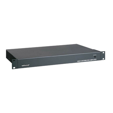
Infinova V2040 Installation instructions

V2040 Series
Video Matrix Switching System
Installation/Operation Instructions
This manual applies to below series products:
V2040/V2040X/V2040N/V2040NX
V2040 Video Matrix Switching System features comprehensive functions for any security/surveillance
systems, pre-configuration to assure the highest level of reliability, and modular architecture for ease of
installation, operation and expansion. V2040 Video Matrix Switching System represents the peak of video
switching technology while remaining a highly cost effective solution. Utilizing the latest advancement of
microprocessor and LSI technology, V2040 Video Matrix Switching System can provide automated
electronic surveillance or it can allow even a single user to control an entire CCTV system of up to 1024
video inputs by 128 video outputs. In an automated environment the user can pre-define tours and salvos to
be performed separately on individual monitors. For maximum security, an available video-looping module
provides extension of the original video for output to a DVR or other recording device. Available windows
based system setup software greatly simplifies the initial setup procedure as well as ongoing maintenance of
system parameters. The matrix communicates with controllers or PCs via either RS-232 or TCP/IP protocols.
Up to 64 V2040s can be interconnected in one network video system via TCP/IP. The V2040 external Central
Processing Unit (CPU) is the controlling unit for each individual SITE in a Networking System. Each Site is
a complete CCTV surveillance system, providing both LOCAL and REMOTE control of certain resources of
other SITES within the network. Individual V2040 SITES are interconnected by video trunk cables.


Notice
Copyright Statement
This manual may not be reproduced in any form or by any means to create any derivative such as translation, transformation, or adaptation
without the prior written permission of Infinova.
Infinova reserves the right to change this manual and the specifications without prior notice. The most recent product specifications and user
documentation for all Infinova products are available on our website www.infinova.com.
Trademarks
Infinova
®
is a trademark of Infinova.
Copyright © 1993-2014 Infinova. All rights reserved.
All other trademarks that may appear belong to their respective proprietors.
FCC Warning
V2040 Video Matrix Switching System complies with Part 15 of the FCC rules.
Operation is subject to the following two conditions.
•This device may not cause harmful interference.
•This device must accept any interference received, including interference that may cause undesired operation.
V2040 Video Matrix Switching System has been tested and found to comply with the limits for Class A digital device, pursuant to Part 15 of
the FCC rules. These limits are designed to provide reasonable protection against harmful interference when the equipment is operated in a
residential environment. This equipment generates, uses, and can radiate radio frequency energy and, if not installed and used in accordance
with the instructions, may cause harmful interference to radio communications. However, there is no guarantee that interference will not
occur in a particular installation.

Read this manual carefully before installation. This manual should be saved for future use.
Important Safety Instructions and Warnings
•Electronic devices must be kept away from water, fire or high magnetic radiation.
•Clean with a dry cloth.
•Provide adequate ventilation.
•Unplug the power supply when the device is not to be used for an extended period of time.
•Only use components and parts recommended by manufacturer.
•Position power source and related wires to assure they will be kept away from ground and access way.
•Refer all service matters to qualified personnel.
•Save product packaging to ensure availability of proper shipping containers for future transportation.
Indicates that the un-insulated components within the product may carry a voltage harmful to humans.
Indicates operations that should be conducted in strict compliance with instructions and guidelines contained in this manual.
Warning: To avoid risk of fire and electric shock, keep the product away from rain and moisture!

Table of Contents
Chapter I General Description ..................................................... 1
1.1 Description............................................................................ 1
1.2 Models .................................................................................. 2
1.3 Features................................................................................. 2
1.4 Important Terminology ......................................................... 2
1.5 System Accessories............................................................... 4
Chapter II System Installation and Hardware Connection ....... 5
2.1 System Module Description.................................................. 5
2.1.1 Matrix Switching Bay ................................................... 5
2.1.2 Central Processing Unit (External CPU) ....................... 5
2.1.3 Power Supply Module ................................................... 5
2.1.4 Data Buffer Module....................................................... 6
2.1.5 Data Buffer Module with Video Loss Detection ........... 6
2.1.6 Video Input Module (VIM) ........................................... 7
2.1.7 Video Output Module (VOM) ....................................... 8
2.2 Module Setup........................................................................ 8
2.2.1 Data Buffer Module Switches ....................................... 8
2.2.2 Switches of Data Buffer Module with Video Loss
Detection ................................................................................ 9
2.2.3 Video Input Module Switches ..................................... 10
2.2.4 Video Output Module Switches .................................. 11
2.3 Installation .......................................................................... 12
2.4 Hardware Connection ......................................................... 12
2.4.1 Video Input Connections............................................. 12
2.4.2 Control Connections.................................................... 13
2.4.3 Video Output Connections .......................................... 13
2.4.4 Alarm Input Connections ............................................ 13
2.4.5 Communication Port Connections............................... 14
2.4.6 Local Relay Output Connections................................. 15
2.4.7 Ethernet Connections .................................................. 15
2.4.8 Power Supply Connections.......................................... 15
2.4.9 Networking Connections............................................. 16
Chapter III System Operation.................................................... 19
3.1 Keyboards ........................................................................... 19
3.2 Keyboard Password Entry................................................... 20
3.3 Video Selection ................................................................... 20
3.4 Camera Control................................................................... 21
3.5 REMOTE Video Selection.................................................. 21
3.6 Controlling Remote Camera Site Functions........................ 21
3.7 Running a Tour ................................................................... 22
3.8 Calling a Preset ................................................................... 22
3.9 Calling a System Salvo ....................................................... 23
3.10 Activating an Auxiliary..................................................... 23
3.11 Acknowledge an Alarm..................................................... 23
Chapter IV System Setup ........................................................... 23
4.1 System Reset....................................................................... 23
4.2 Monitor Display Arrangement ............................................ 23
4.3 Monitor Tour Programming ................................................ 24
4.4 Setting Date Format/Setting Day of the Week .................... 24
4.5 Setting Preset ...................................................................... 25
4.6 Camera Lockout.................................................................. 25
4.7 Arming Monitors ................................................................ 25
4.7.1 Arm Display Modes .................................................... 25
4.7.2 Arm Clearance Methods.............................................. 26
4.7.3 Monitor Arming Types................................................ 26
4.7.4 Arming/Disarming a Monitor...................................... 27
Chapter V Menu Programming ................................................. 28
5.1 Main Selection Menu.......................................................... 28
5.2 Menu Navigation and Operation......................................... 28
5.3 System Menu ...................................................................... 28
5.3.1 Setting Time and Date................................................. 28
5.3.2 Setting System Tours .................................................. 30
5.3.3 Set System Salvos ....................................................... 32
5.3.4 Set Event Timer........................................................... 33
5.3.5 Set Alarm Contact ....................................................... 35
5.3.6 Monitor Status............................................................. 37
5.4 Monitor Menu..................................................................... 38
5.5 Camera Menu...................................................................... 40
5.5.1 Assign Pseudo Cameras .............................................. 40
5.5.2 Camera Title................................................................ 41
5.6 Port Menu ........................................................................... 41
5.7 Access Menu....................................................................... 42
5.7.1 Keyboard Numbers ..................................................... 42
5.7.2 Keyboard/Monitor....................................................... 43
5.7.3 Keyboard/Camera View.............................................. 43
5.7.4 Keyboard/Camera Control .......................................... 44
5.7.5 Monitor/Camera Access.............................................. 45
5.7.6 Monitor/Contact Access.............................................. 45
5.7.7 Keyboard/Remote Site ................................................ 46
5.8 Priority Menu...................................................................... 46
5.8.1 User Identification....................................................... 46
5.8.2 Set Keyboard............................................................... 47

5.8.3 Set User .......................................................................47
5.8.4 Set Priority...................................................................48
5.9 Networking Configuration Menu ........................................49
5.9.1 Local Site Number.......................................................49
5.9.2 Video Trunk Assignments ...........................................51
5.9.3 Remote Site IP Address...............................................52
Appendix I System Alarm Programming ..................................53
Appendix II ASCII / HEX System Control Codes ....................53
Appendix III Specifications ........................................................54
Appendix IV Typical System Application ................................. 55
Appendix V Multilevel Networking Diagram............................58
Appendix VI Cable Diameter Calculation and Lightning &
Surge Protection....................................................... 59

1
Chapter I General Description
1.1 Description
V2040 Matrix Video Switching system, featuring scalable and
high-density modular structure as well as Ethernet network control
capability, provides flexible and cost-effective solutions to any
security/surveillance application.
Network Video Capability
Multiple V2040s can be networked to provide both local and remote
control of the site cameras via the TCP/IP protocol. Each V2040
unit in the network is referred to as a node, and each node in the
network maintains its full functions. To identify V2040 in a network,
each unit is allocated a unique site number, which is assigned
through the programming menu.
Networking of V2040 systems is required when
1. Two or more individual V2040 systems need to share video and
control features
2. More than 1,024 cameras are required
3. More than 128 monitors are needed for the system (without full
cross-point)
4. Cameras connected to remote V2040s need to be accessed.
The V2040 network communicates over an Ethernet network,
therefore, an Ethernet network will need to be installed.
To connect the V2040 to a network, just plug one end of the
Ethernet cable into a Hub or Switch, while the other end of the cable
plugs into to the Port marked ETHERNET on the rear panel of the
V2040 CPU.
Note:
1. All V2040 CPUs come with a pre-configured network ID of
192.168.0.0, the system administrator must make sure that all
V2040s work at this network ID setting when integrating the
V2040s into an existing Ethernet network.
2. For a specific network setting, please contact the manufacturer
for pre-setting the network ID to ensure they work with existing
devices such as PC’s attached to the same network.
3. Infinova strongly recommends the installer establish a separate
Ethernet network for the V2040 network to ensure uninterrupted
operation and system security.
The V2040 video matrix switching system used in a network
configuration is a CCTV surveillance system for multiple control
SITES, with multiple video inputs, multiple video outputs, and
multiple control stations at each SITE. The V2040 Central
Processing Unit (CPU) is the controlling unit for each individual
SITE in the networking system. Each SITE is a complete CCTV
surveillance system, providing both LOCAL (independent) control
of all resources connected to the V2040 CPU at that SITE, and
REMOTE control of certain resources of other SITES within the
network. Individual V2040 SITES are interconnected via Ethernet
and video trunk lines.
Flexible Design
V2040 adopts a high-density modular design that allows easy
system expansion. It typically consists of a Matrix Switching Bay
and hot-swappable modules including Power Supply Module,
Central Processing Unit (CPU) Module, Data Buffer Module (with
optional Video Loss Detection), Video Input Module (VIM) and
Video Output Module (VOM). Flexible system configurations,
therefore, can be easily customized to meet various requirements.
To facilitate system expansion, V2040 also provides outstanding
Ethernet network control and looping through capability.
Easy Operation & Powerful Programming
Utilizing microprocessor and LSI technology, V2040 can provide
automated electronic surveillance, allowing even a single user to
control an entire CCTV system. A maximum of 1024 video inputs
and 128 video outputs can be controlled from any one of up to 40
keyboards, PCs and other devices.
V2040 provides powerful menu-driven programming, featuring 64
user-defined system tours, 64 salvos, 35 event timers, 15 alarm
display / clearance methods. Optional character information (e.g.,
date, time, video input number, video output title and monitor status)
can also be programmed to aid site surveillance and system
operation.
Available Windows-based system setup software greatly simplifies
the initial setup procedure as well as ongoing maintenance of
system parameters. The matrix communicates with controllers or
PCs via either RS-232 data or TCP/IP protocols. Optional GUI
software V2000/2210 further simplifies system operation and
programming by integrating all functions in an easy-to-use
Windows application. Third-party applications written in ASCII
codes can also be adopted for the system.
System Security
System security involves two approaches: System Partitioning and
User Priority. System Partitioning is used to control keyboard access
to monitors, cameras, camera control and alarms. Five
programmable access controls are provided for Partitioning
management in V2040 system.
With User Priority, system administrators can define a maximum of
64 system users, and assign each user a password and a priority
level. Each of the eight priority levels can also be configured as
desired, permitting different access controls for different
users/keyboards.
Continuous Performance
V2040 is designed for continuous duty operation. Therefore, there
will be no need for any inner maintenance once the installation is
finished. System programming, either via keyboard or GUI software,
is noninvasive and does not require rebooting or power cycling for
storage and/or execution of programmed settings.

2
All the communication ports adopt standard low-voltage interfaces
such as RS-232, High Speed Data Line and N.C/N.O switching
signal, and all connections/disconnections do not require rebooting
or power cycling. It is also the same with video connections.
Easy Installation & Maintenance
Each hot-swappable module locates status indicator(s) on its front
panel to provide easy installation, maintenance and
trouble-shooting.
V2040 is designed for EIA 19" (48.26cm) rack-mounting
(recommended) and desktop-mounting.
1.2 Models
Pre-configured System
V2040-XXXX×ZZZ Pre-configured matrix system
including switching bays, external
CPU, input modules and output
modules. XXXX×ZZZ specifies
numbers of video inputs (in multiples
of 16) and video outputs (in multiples
of 4). For example, V2040-640×32 is a
pre-configured matrix with 640 video
inputs and 32 video outputs.
Optional Products
V2903DBVL Data buffer module with video loss
detection (256 inputs per unit). Add -K
for field conversion units.
V2903LP Video looping panel with two 30"
coaxial ribbon cables, 16 inputs each.
Add -K for field conversion units.
V2924HS Hot switch for dual CPU operation
(requires purchase of additional CPU).
Spare Products
V2901 High-density bay, includes power
supply module
V2902 High-density bay, bi-level, includes
power supply module
V2923CPU External CPU
V2903PS Power supply module
V2903DB Built-in data buffer module
V2903VI Video input module with back card,
add -1 for single bay, -2 for level 1, -3
for level 2, or -4 for higher level
V2903VO Video output module with back card,
add -1 for single slot or -2 for double
slots.
V2903VIC Video input card.
V2903VOC Video output card without back card.
V2903VIB Back card for video input, add -1 for
single bay, -2 for level 1, -3 for level 2,
or -4 for higher level
V2903VOB Back card for video output, add -1 for
single slot or -2 for double slots.
1.3 Features
zUp to 1,024 video inputs by 128 video outputs.
zScalable high-density architecture for easy expansion.
zEthernet network controllable, external CPU for added
networking features
zWindows-based multimedia management software.
zBuilt-in system diagnostics and dedicated system status report.
zControl of fixed or variable speed pan/tilt and dome cameras on
Manchester, RS-422, or RS-485 PTZ protocols.
zAvailable internal video loss detection.
z10 flexible RS-232 ports (expandable to 40 with V2405-4).
zIndependent monitor tour.
z64 tours, 35 event timers and 64 salvos.
zAutomatic alarm call-up, up to 1024 alarm inputs.
z15 alarm display/clearance methods.
zInternal partition management including: input-to-output display,
keyboard-to-input display, and keyboard-to-input control.
zUser priority and password management
zUp to 64 V2040 nodes can be inter-connected in one network
video system.
zAll V2040s maintain local operations (local camera switching,
control, etc.) when the existing LAN goes off-line.
zAn V2040 can be remotely located as far as the transmission type
and path allows. Infinova offers Fiber Optic systems for virtually
unlimited video transmission and communication distance.
1.4 Important Terminology
1. System Keyboard
System Keyboards are the Infinova keyboards for system
control and programming, including V2117, V2116 and V2115
full system keyboard, and V2110 operator control keyboard.
V2040 can be controlled by up to 40 Infinova series keyboards
including V2116 and V2110 via RS-232 ports and by network
keyboards. Various keyboards can be combined for operation.
Please refer to relevant keyboard manuals for further
instructions.
2. Preset, Salvo, System Tour and Event Timer
zPreset enables the system to pre-define and save camera
scenes, which can be called up for display either
automatically by the system upon alarms or by operators via
keyboards. The Infinova series receivers and Super Dome
cameras are capable of defining up to 128 such camera
scenes. Descriptions for the relevant scenes can also be
displayed on monitors at the same time.
zSalvo permits users to switch a group of cameras to a group
of monitors, hereby providing convenient surveillance over
different scenes simultaneously.
zSystem Tour enables operators to display different camera
scenes, presets and salvos continuously on the same monitor.
One camera scene or one preset can be included in the same
Tour multiple times.
zEvent Timer permits the system to automatically call up
system tours at a pre-programmed time.

3
3. Monitor Tour
A monitor Tour is a temporary sequence of cameras for a called
monitor. The sequence can only be displayed on the called
monitor.
4. Control Interface
V2040 system provides its controllers and auxiliaries with
following interfaces:
Multiple V2040 sites establish inter-communication via TCP/IP
in a network video system;
Controller stations (such as keyboards, PCs) establish
communication with V2040 via RS-232 interfaces;
The V2431 Alarm Interface Units communicate with V2040
via RS-232 interfaces (in Central Processing Module) to
control alarms;
The Monitor specifically for menu programming (PROG MON)
Communicates with V2040 via PROG MON port (in Central
Processing Module);
The V2411 Code Generator/Distributors, looping through
DATA LINE with V2040, are used to provide Manchester or
control code for site cameras.
Infinova series Followers (including V2421, V2422, V2423)
switch external circuits when designated cameras are called up
to designated monitors (V2421), when designated monitors are
in alarm conditions (V2422), or when designated auxiliaries
are called up (V2423). They all communicate with V2040 via
high-speed DATA LINE.
5. System Partitioning
System partitioning provides users with the following access
controls:
zKeyboard-to-Monitor: prevents selected keyboards from
accessing selected monitors;
zKeyboard-to-Camera View: prevents selected keyboards
from calling up selected cameras to a monitor for viewing
and/or displaying;
zKeyboard-to-Camera Control: prevents selected keyboards
from controlling remote functions on selected cameras;
zMonitor-to-Camera: prevents selected monitors from
displaying video from selected cameras in the system;
zKeyboard-to-Remote site: prevents selected keyboards from
controlling remote site.
6. Alarm Handling
V2040 system, when communicating with the V2431 Alarm
Interface Units, provides up to 1024 alarm inputs, and features
powerful alarm handlings such as:
zCalling up any system video input upon alarm;
zCalling up pre-defined scenes upon alarm;
zTriggering auxiliary relay switches for site cameras upon
alarm.
7. Auxiliary Outputs
Local auxiliary outputs are provided via the V2431 Alarm
Interface Units (AIUs) to activate VCRs or other alarm
devices.
8. Pseudo Numbers and Real Numbers
V2040 system assigns Pseudo Numbers for up to 1024 local
cameras or cameras of the remote site for ease of system
management. A Pseudo Number is the logical number the
system assigns to a specific camera. The camera's Real Number,
the actual physical camera number, can also be used in the
system.
9. Network Node
Each V2040 in the network is referred to as a node. Each node
in the network maintains all of its full features. To identify
V2040s in a network, each unit is allocated a unique site
number through the programming menu.
10. Power Supply and its installation
System Power Supply herein refers to the standard power
supply for V2040. V2040 can be powered with 120VAC/60Hz
or 230VAC/50Hz standard power supply.
NOTE: When powering V2040, check that the power supply
specifications correspond to those required. The use of improper
appliances may seriously compromise the safety of the personnel
and the installation.

4
1.5 System Accessories
Table 1 -1
V2116 series
System Keyboards
zFull system programming and control
zCommunicates with matrix switching systems via RS-232 or with Ethernet network via
TCP/IP
zLCD displays of camera and monitor
zDirect control via Manchester or RS-485 outputs
zFixed and variable speed joystick
V2117 series
System Keyboard
zFull system programming and control
zCommunicates with matrix switching systems via RS-232 or with Ethernet network
zLCD displays of camera and monitor
zDirect control via Manchester or RS-485 outputs
zFixed and variable speed joystick
zCommunicates with DVR via RS-485 port or Ethernet port
V2110
Operator Keyboard
z4 digital LED displays of camera and monitor
zFixed and variable speed joystick
zMonitor tour programming and control
zAlarm Acknowledge clear
zCommunicates with all Infinova matrix switching systems via RS-232
V2405-4 Port Expander zExpands each RS-232 port on the system's CPU into four RS-232 ports
V2000/V2210
User Interface Software
zWindows based
zGraphical User Interface
zComplete system control using on-screen keyboard
zLive video windows (optional video card)
zE-maps, control menus and icons, password encryption and login
zConvenient arming/disarming
V29X3SW
System Setup Software
zWindows based
zUploads and downloads the system setup data
V1691 Series
Receiver/Drivers
zManchester or RS-485 (INFINOVA, SAMSUNG, PELCO-P/D) control code input
z24VAC or 14VDC output optional
zMultiple presets and autopan functions
zLocal diagnostic mode
zPan/tilt and camera control
V2411 Series
Code Converters
zData line signal input to 64 Manchester code outputs
zData line signal input to 16 RS-485 code outputs
zData line signal input to 8 RS422 code outputs
V2431
Alarm Interface Unit
z64 alarm inputs (normally open or normally closed contacts)
zMultiple units can be cascaded on 1 RS-232 data stream
zAutomatic alarm call-up and video switching
zCompatible with products from leading manufacturers
V2421
Switch Follower
zProvides 2 groups of 16 (32) Double Pole Form-A relays
zRelays follow switching of camera to monitor
zManually or automatically activates accessories such as Intercoms and lights
zMultiple units can be cascaded for system expansion
V2422
Alarm Follower
zProvides 2 groups of 16 (32) Double Pole Form-A relays
zRelays follow the alarmed monitors
zMultiple units can cascaded for system expansion
V2423
Auxiliary Follower
zProvides 2 groups of 16 (32) Double Pole Form-A relays
zRelays respond to activation of linked camera auxiliary command
zManually or automatically activates auxiliary accessories
zMultiple units can be cascaded for system expansion

5
Chapter II System Installation and
Hardware Connection
2.1 System Module Description
2.1.1 Matrix Switching Bay
The V2901/2902 (see V2040 Models) matrix switching bay includes
a physical chassis, a back plane, and a power supply module. These
two models both feature the capability of looping the DATA LINE
input and an external vertical sync pulse to other bays. A single bay
can accommodate a total of 16 video input modules (VIMs) and
video output modules (VOMs) combinations.
Specifications:
Power: 60 watts (full system)
Size: 10.5" (height) x 19" (full-width)
Weight: 60 lbs. (28 kg) (full system)
2.1.2 Central Processing Unit (External CPU)
The software-embedded Central Processing Unit (CPU) Module is
the "heart" of the switching system. It controls the switching bays
of V2040 system, provides PTZ controls for site cameras, and
offers the programming menus for system setup.
The front panel of the External CPU features a POWER LED
indicator, a RESET button, and LCD panel for displaying the
system date and time.
The rear panel includes ten RS-232 ports, an Ethernet port, two
DATA LINE outputs and a system programming monitor output
(PGM).
RESET
03 --20 --2003 12:00:00
POWER
SYSTEM CPU
1 2 3
Infinova
R
Figure 2-1. V2040 External CPU Front Panel
Front Panel
1. RESET BUTTON – This button is used to reset the external
CPU.
2. Date – Time Display – This LCD panel indicates the current
system date and time.
3. Power – This LED indicates the system power status.
2 3
DATA LINE RS232 PORTS ETHERNET PROG MON
1 2 1 2 34 56 7 8 9 1011
1 4 5 6
Figure 2-2. V2040 External CPU Rear Panel
Rear Panel
1. Data Line 1 – Routes V2040 CPU control signal to pan/tilt, lens,
and auxiliary functions at suitably equipped sites, up to 1024.
Data Line 1 also routes the matrix switching information for
video outputs 1- 64.
2. Data Line 2 – Routes V2040 matrix switching information for
video outputs 65-128.
3. RS-232 PORTS - These ten RS-232 ports provide interfaces for
communication with keyboards, PCs, and other devices such as
the V2431 Alarm Interface Unit. Each port is programmable for
baud rate, data bits, stop bits, parity and type of use.
4. Ethernet Port - This Ethernet port is used to connect V2040 to a
Hub or switch via TCP/IP to form a network video system (For
more information, refer to V2040N networking configuration).
5. PGM OUT - The output for the system programming monitor
(PGM) that displays programming menus.
6. Power Cord.
2.1.3 Power Supply Module
The power supply module converts AC power to DC voltages for
modules in the matrix switching bay.
Front Panel
The front panel (Figure 2-3.1) highlights the following features:
1. SYNC TEST ON/OFF LED - This LED (red) is illuminated
when the SET UP/NORMAL switch (2) is in the SET UP
position.
2. SET UP/NORMAL SWITCH - This switch enables sync test and
adjustment when set to the SET UP position.
3. SYNC LOSS LED - This LED (red) indicates whether sync is
locked (LED off) or not (LED on).
4. SYNC REFERENCE SELECTION SWITCH - The switch
selects one of the following video sync references:
EXT V-DRIVE (Up position): Selects the external vertical drive
input.
EXT CAM (Central position): Selects composite video.
AC LINE (Down position): Selects the AC line.
5. SYNC PHASE ADJUSTMENT - It adjusts the phase of the sync
pulse when Switch 4 is set.
6. +9 VDC and -9 VDC LEDs - If these two LEDs (green) are
illuminated, it indicates the presence of DC voltages.
Note: For 230 VAC systems, the output voltages are +/- 8 VDC.
7. POWER ON/OFF SWITCH - The power switch for the bay.
Rear Panel
The rear panel (Figure 2-3.2) highlights the following features:
1. SERIAL # TAG - The tag bears the product serial number.
2. DATA LINE IN - The input for DATA LINE.
3. DATA LINE OUT - The looping output for DATA LINE.
Please note that this line must be terminated with a 75-ohm
terminator.
4. EXTERNAL SYNC IN - The input for external vertical
synchronous pulse, either camera sync or an externally created
pulse.
5. EXTERNAL SYNC OUT - The looping output for external sync.
Please note that this line must be terminated with a 75-ohm
terminator.

6
SET UP
NORMAL
SYNC
LOSS
EXT V-DRIVE
EXT CAM
AC LINE
PHASE
+9 VDC
-9 VDC
1
2
3
4
5
6
7
Model: V2040
[]
S/N: xxxxx
IN
OUT
DATA LINE
IN
OUT
EXT
SYNC
1
2
3
4
5
Figure 2-3.1. Power Supply Figure 2-3.2. Power Supply
Module on rear panel Module on front panel
Fusing
The power supply module has four replaceable fuses on its circuit
board.
Maintenance personnel must ensure that replacement fuses meet
national and local use code requirements.
Table 2 -1
Fuse Ratings
For 120VAC Systems:
F1: 125V, 5 AMP, 5 x 20 mm
F2: 125V, 5 AMP, 5 x 20 mm
F3: 250V, SB, 0.5 AMP, 5 x 20 mm, UL listed
F4: 250V, SB, 0.5 AMP, 5 x 20 mm, UL listed
For 230VAC CE Compliant Systems:
F1: 250V, T, 3.15 AMP, 5 x 20 mm
F2: 250V, T, 3.15 AMP, 5 x 20 mm
For 230VAC Non-CE Compliant Systems:
F1: 125V, 5 AMP, 5 x 20 mm
F2: 125V, 5 AMP, 5 x 20 mm
F3: 250V, T, 0.25 AMP, 5x20 mm
F4: 250V, T, 0.25 AMP, 5 x 20 mm
2.1.4 Data Buffer Module
The Data Buffer Module has two major functions:
1. Video Distribution: In a multiple-bay system, it distributes
switched video from a bay's Video Input Modules to other bays.
The video signals from these outputs only contain standard video,
without any character information.
2. Data Filtering: It filters incoming system information from the
DATA LINE.
The V2903DB rear panel has 16 video output BNCs for connecting
Video Output Modules in other switching bays. The following
figures illustrate various types of Data Buffer Module rear panels.
Output 1
Output 8
Output 16
Output 1
Output 8
Output 16 Output 16
Output 8
Output 1
1
8
9
16
O
U
T
O
U
T
T
E
S
T
/
E
X
P
A
N
S
I
O
N
O
N
L
Y
1
4
5
8
9
12
13
16
v
1
4
5
8
9
12
13
16
1
4
5
8
9
12
13
16
1
4
5
8
9
12
13
16
Output 1
Output 8
Output 16 Output 16
Output 8
Output 1
Figure 2-4.1 Figure2-4.2 Figure 2-4.3 Figure2-4.4 Figure 2-4.5 Figure 2-4.6
Figure 2-4. Rear Panels of Data Buffer Modules
Icon Definition: The icon combinations indicate switched
video inputs from different camera groups.
- The switched video inputs from cameras 1 to 256.
- The switched video inputs from cameras 257 to 512.
- The switched video inputs from cameras 513 to 768.
- The switched video inputs from cameras 769 to 1024.
Figure Description:
zFigure 2-4.1 - Rear Panel
zFigure 2-4.2 - Rear Panel with 16 BNCs (in a camera card bay,
no monitor modules)
zFigure 2-4.3 - Rear Panel with 16 BNCs (for cameras 1-256 in a
multiple-bay system)
zFigure 2-4.4 - Rear Panel with 16 BNCs (for cameras 257-512 in
a multiple-bay system)
zFigure 2-4.5 - Rear Panel with 16 BNCs (for cameras 513-768 in
a multiple-bay system)
zFigure 2-4.6 - Rear Panel with 16 BNCs (for cameras 769-1024
in a multiple-bay system)
2.1.5 Data Buffer Module with Video Loss Detection
The Data Buffer Module with Video Loss Detection also provides
the two functions of a common Data Buffer Module, i.e., Video
Distribution and Data Filtering. What makes it different, however,
is its capability of detecting video signal loss for each camera input.
A single module can detect video loss for up to 256 cameras.
The module must be placed in a matrix switching bay that contains
Video Input Modules, and the bay must be connected to the
highest-numbered monitor output.
Front Panel
The front panel of a Data Buffer Module with Video Loss Detection
(Figure 2-5) highlights the following LEDs:

7
1. POWER LED - Indicates power-on status.
2. ALARM LED - Indicates Video/Sync Loss.
3. SYNC LED - Indicates presence of Sync.
VIDEO LEVEL LEDs:
4. H LED - Indicates High video content.
5. M LED - Indicates Medium video content.
6. L LED - Indicates Low video content.
ALARM
SYNC
VIDEO
LEVEL
H
M
L
1
2
3
4
5
6
Figure 2-5. Front Panel
Rear Panel
The rear panel of a Data Buffer Module with Video Loss Detection
has 15 video output BNCs for connection to Video Output Modules,
and one 8-pin, RJ-45 RS-232 connector for Video Loss Detection
data output and Alarm Contact output to an RS-232 port on the
CPU module for processing.
The following figures illustrate various types of the rear panels of
Data Buffer Module with Video Loss Detection.
1
4
5
8
9
12
13
v
15
1
4
5
8
9
12
13
15
1
4
5
8
9
12
13
15
1
4
5
8
9
12
13
15
1
8
9
15
O
U
T
O
U
T
T
E
S
T
/
E
X
P
A
N
S
I
O
N
O
N
L
Y
Figure2-6.1 Figure2-6.2 Figure2-6.3 Figure2-6.4 Figure 2-6.5 Figure 2-6.6
Figure 2-6. Rear Panels of Data Buffer Modules with Video Loss
Detection
Icon Definition: The icon combinations indicate switched
video inputs from different camera groups.
- The switched video inputs from cameras 1 to 256.
- The switched video inputs from cameras 257 to 512.
- The switched video inputs from cameras 513 to 768.
- The switched video inputs from cameras 769 to 1024.
Figure Description:
zFigure 2-6.1 - V2903DBVL-00 Rear Panel
zFigure 2-6.2 - V2903DBVL-01 Rear Panel (in a camera card bay,
no monitor modules)
zFigure 2-6.3 - V2903DBVL-11-18 Rear Panel (for cameras 1-256
in a multi-bay system)
zFigure 2-6.4 - V2903DBVL-21-28 Rear Panel (for cameras
257-512 in a multi-bay system)
zFigure 2-6.5 - V2903DBVL-31-38 Rear Panel (for cameras
513-768 in a multi-bay system)
zFigure 2-6.6 - V2903DBVL-41-48 Rear Panel (for cameras
796-1024 in a multi-bay system)
2.1.6 Video Input Module (VIM)
The VIM is the module that performs the actual video switching.
Video inputs (up to 16) are connected at the VIM rear panel.
Infinova provides four different types of VIM rear panels,
illustrated below:
1
4
5
8
9
12
13
16
Input 1
Input 8
Input 16
111
81616
O
U
T
I
N
O
U
T
O
U
T
I
N
O
U
T
Figure 2-7.1 Figure 2-7.2 Figure 2-7.3 Figure 2-7.4
Figure 2-7. Rear Panels of Video Input Modules
Icon Definition: The icon indicates video inputs.
Figure Description:
zFigure 2-7.1 - The rear panel of V2903VI-1 has 16 BNCs for
video inputs. The module is used for a single-bay system.

8
zFigure 2-7.2 - The rear panel of V2903VI-2 has eight BNCs and
one 34-pin connector. The eight BNCs are used for the upper
group of eight video inputs.
zFigure 2-7.3 - The rear panel of V2903VI-3 has eight BNCs and
two 34-pin connectors. The eight BNCs are used for the lower
group of eight video inputs, hereby accomplishing a larger group
of 16 video inputs.
zFigure 2-7.4 - The rear panel of V2903VI-4 has only two 34-pin
connectors. The module is used for expansion in a multiple-bay
system.
2.1.7 Video Output Module (VOM)
The Video Output Module (VOM) attaches additional information
(i.e., title, time and date) to a switched video output. Each VOM has
four video outputs on its rear panel. Infinova provides two VOM
models with different rear panels, illustrated below.
Icon Definition: The icon combinations indicate switched
video inputs from different camera groups.
- The switched video inputs from cameras 1 - 256.
- The switched video inputs from cameras 257 - 512.
- The switched video inputs from cameras 513 - 768.
- The switched video inputs from cameras 769 - 1024.
Figure Description:
zFigure 2-8.1 - The rear panel of V2903VO-1 has 16 BNCs,
divided into four sections. The bottom four-BNC section (marked
as "OUT") is for video outputs, while the other three are used in a
multiple-bay system for video inputs from other matrix switching
bays.
zFigure 2-8.2 - The rear panel of V2903VO-2 has 20 BNCs,
divided into five sections. The bottom-left four-BNC section
(marked as "OUT") locates video outputs, while the other four
are used in a multiple-bay system for video inputs from other
matrix switching bays.
1
4
1
4
1
4
1
4
O
U
T
1
4
1
4
1
4
1
4
1
4
O
U
T
Figure 2-8.1 Figure 2-8.2
Figure 2-8. Rear Panels of VOMs
2.2 Module Setup
Different system applications may require different settings for the
internal jumper switches on system modules. This section provides
instructions on switch setups for four V2040 modules: Data Buffer
Module, Data Buffer Module with Video Loss Detection, Video
Input Module and Video Output Module.
CAUTION: THE PRESENCE OF NON-INSULATED
COMPONENTS WITH HAZARDOUS VOLTAGES
REQUIRES QUALIFIED SERVICE PERSONNEL TO
PERFORM THE FOLLOWING PROCEDURES ONLY.
2.2.1 Data Buffer Module Switches
The Data Buffer Module Switches features two functions: Video
Switching and Data Filtering (see System Module Description -
Data Buffer Module). The latter requires setting of two 8-position
DIP switches, SW1 and SW3.
zSwitch SW1 sets the ON/OFF status of the module's Data
Filtering. If Switch S1 is set to the ON status, all information
passes and Switch S3 is not used; if OFF, only specified
information passes and S3 must be set accordingly.
zSwitch SW3 sets the camera and monitor group numbers
associated with particular switching bays. Specified information
is filtered only for these bays.
18
SW1
ON
18
SW3
ON
Figure 2-9. Data Buffer Module Switches
Table 2-2. Switch SW1 Settings
Filtering Status
Switch Positions
(1=ON, 0=Off, X=Don't care)
8 7 6 5 4 3 2 1
On (all information
passed.) 1 × × × × × × ×
OFF (only specified
information passed). 0 × × × × × × ×
Note: For matrix switching bays containing V2903VO modules, S1
must be set to ON status, i.e., to pass all information to these bays.

9
Table 2-3. Switch SW3 Settings
Camera Monitor
Switch Positions
(1=ON, 0=Off, X=Don't care)
8 7 6 5 4 3 2 1
1-256 1-16 × × 0 0 × 0 0 ×
257-512 1-16 × × 1 0 × 0 0 ×
513-768 1-16 × × 0 1 × 0 0 ×
769-1024 1-16 × × 1 1 × 0 0 ×
1-256 17-32 × × 0 0 × 1 0 ×
257-512 17-32 × × 1 0 × 1 0 ×
513-768 17-32 × × 0 1 × 1 0 ×
769-1024 17-32 × × 1 1 × 1 0 ×
1-256 33-48 × × 0 0 × 0 1 ×
257-512 33-48 × × 1 0 × 0 1 ×
513-768 33-48 × × 0 1 × 0 1 ×
769-1024 33-48 × × 1 1 × 0 1 ×
1-256 49-64 × × 0 0 × 1 1 ×
257-512 49-64 × × 1 0 × 1 1 ×
513-768 49-64 × × 0 1 × 1 1 ×
769-1024 49-64 × × 1 1 × 1 1 ×
2.2.2 Switches of Data Buffer Module with Video Loss
Detection
Apart from the two functions of common Data Buffer Module, the
Data Buffer Module with Video Loss Detection highlights the
capability of detecting video loss for each camera.
The module has three 8-position DIP switches, respectively labeled
as "SW1", "SW2" and "SW3", to set up parameters for these
functions.
18
SW1
ON
18
SW3
ON
18
SW2
ON
S6
Figure 2-10. Switches of Data Buffer Module with Video Loss
Detection
zSwitch SW1 sets the switching bay type, the ON/OFF status of
filtering (the same as a common Data Buffer Module), the baud
rate for the RJ-45 port, and the Alarm Contact mode
(factory-reserved for indicating Video/Sync Loss Detection).
Note: Position 7 of SW1 should be set to ON to enable the
module to perform video loss detection.
zSwitch SW2 defines the communication type of the RJ-45 port,
and enables/disables the module's front panel LED.
zSwitch SW3 sets the camera and monitor group numbers
associated with particular switching bays. The specified
information is filtered only for these bays. Note: The setup of
switch SW3 is different for different type of switching bay.
In addition, a 3-position jumper labeled as "S6" (see Figure 2-11) is
also provided to enable/disable the on-board saving capability. If
enabled, the parameters concerning the video loss detection,
defined via menu programming, will be stored in the on-board
memory of the DBVL.
Table 2-4. Switch SW1 Settings
Function
Switch Positions
(1=ON, 0=Off, X=Don't care)
8 7 6 5 4 3 2 1
Normal switching bay × × 0 × × × × ×
Dense switching bay × × 1 × × × × ×
Video loss detection
enabled. ×1××××××
Video loss detection
disabled. ×0××××××
Allinformationpassed. 1×××××××
Only specific
information passed. 0×××××××
1200 baud rate × × × × × × 0 0
2400 baud rate × × × × × × 0 1
4800 baud rate × × × × × × 1 0
9600 baud rate × × × × × × 1 1
Table 2-5. Switch SW2 Settings
Function
Switch Positions (1=ON, 0=Off)
8 7 6 5 4 3 2 1
RS-232 × 0 0 0 0 0 1 1
Front panel LED ON 1 × × × × × × ×
Front panel LED OFF 0 × × × × × × ×
Table 2-6. Switch SW3 Settings
For Dense Switching Bay:
Camera Monitor
Switch Positions
(1=ON, 0=OFF, X=Don't care)
1 2 3 4 5 6 7 8
1~256 1~32 × 0 × × 0 0 × ×
257~512 1~32 × 0 × × 0 1 × ×
513~768 1~32 × 0 × × 1 0 × ×
76~1024 1~32 × 0 × × 1 1 × ×
1~256 33~64 × 1 × × 0 0 × ×
257~512 33~64 × 1 × × 0 1 × ×
513~768 33~64 × 1 × × 1 0 × ×
769~1024 33~64 × 1 × × 1 1 × ×

10
Table 2-7. Switch SW3 Settings
For Normal Switching Bay:
Camera Monitor
Switch Positions
(1=ON, 0=OFF, X=Don't care)
1 2 3 4 5 6 7 8
1~256 1~16 × 0 0 × 0 0 × ×
257~512 1~16 × 0 0 × 0 1 × ×
513~768 1~16 × 0 0 × 1 0 × ×
769~1024 1~16 × 0 0 × 1 1 × ×
1~256 17~32 × 0 1 × 0 0 × ×
257~512 17~32 × 0 1 × 0 1 × ×
513~768 17~32 × 0 1 × 1 0 × ×
769~1024 17~32 × 0 1 × 1 1 × ×
1~256 33~48 × 1 0 × 0 0 × ×
257~512 33~48 × 1 0 × 0 1 × ×
513~768 33~48 × 1 0 × 1 0 × ×
769~1024 33~48 × 1 0 × 1 1 × ×
1~256 49~64 × 1 1 × 0 0 × ×
257~512 49~64 × 1 1 × 0 1 × ×
513~768 49~64 × 1 1 × 1 0 × ×
769~1024 49~64 × 1 1 × 1 1 × ×
Enables the parameters to be saved on board.
Disables the on-board saving capability.
Figure 2-11. Jumper S6 Settings
2.2.3 Video Input Module Switches
The Video Input Module is the module that performs the actual
video switching. Each module can switch up to 16 video inputs to a
maximum of 64 desired outputs.
The module has two 8-position DIP switches, but only Switch SW1
is used here to define camera groups and monitor groups that the
module is desired to respond to.
Figure 2-12. Video Input Module Switches
Table 2-8. Switch SW1 Settings
Switch Positions
(1=ON, 0=Off, X=Don't care)
Monitor 1 2 3 4 5 6 7 8
1- 16 0 0 × × × × × ×
17- 32 0 1 × × × × × ×
33- 48 1 0 × × × × × ×
49 - 64 1 1 × × × × × ×
Camera
1-16 × × 0 0 0 0 0 0
17-32 × × 0 0 0 0 0 1
33-48 × × 0 0 0 0 1 0
49-64 × × 0 0 0 0 1 1
Switch Positions
(1=ON, 0=Off, X=Don't care)
Camera
65-80 × × 0 0 0 1 0 0
81-96 × × 0 0 0 1 0 1
97-112 × × 0 0 0 1 1 0
113-128 × × 0 0 0 1 1 1
129-144 × × 0 0 1 0 0 0
145-160 × × 0 0 1 0 0 1
161-176 × × 0 0 1 0 1 0
177-192 × × 0 0 1 0 1 1
193-208 × × 0 0 1 1 0 0
209-224 × × 0 0 1 1 0 1
225-240 × × 0 0 1 1 1 0
241-256 × × 0 0 1 1 1 1
257-272 × × 0 1 0 0 0 0
273-288 × × 0 1 0 0 0 1
289-304 × × 0 1 0 0 1 0
305-320 × × 0 1 0 0 1 1
321-336 × × 0 1 0 1 0 0
337-352 × × 0 1 0 1 0 1
353-368 × × 0 1 0 1 10
369-384 × × 0 1 0 1 1 1
385-400 × × 0 1 1 0 0 0
401-416 × × 0 1 1 0 0 1
417-432 × × 0 1 1 0 1 0
433-448 × × 0 1 1 0 1 1
445-464 × × 0 1 1 1 0 0
465-480 × × 0 1 1 1 0 1
481-496 × × 0 1 1 1 1 0
497-512 × × 0 1 1 1 1 1
513-528 × × 1 0 0 0 0 0
529-544 × × 1 0 0 0 0 1
545-560 × × 1 0 0 0 1 0
561-576 × × 1 0 0 0 1 1
577-592 × × 1 0 0 1 0 0
593-608 × × 1 0 0 1 0 1
609-624 × × 1 0 0 1 1 0
625-640 × × 1 0 0 1 1 1
641-656 × × 1 0 1 0 0 0

11
Switch Positions
(1=ON, 0=Off, X=Don't care)
Camera
657-672 × × 1 0 1 0 0 1
673-688 × × 1 0 1 0 1 0
689-704 × × 1 0 1 0 1 1
705-720 × × 1 0 1 1 0 0
721-736 × × 1 0 1 1 0 1
737-752 × × 1 0 1 1 1 0
753-768 × × 1 0 1 1 1 1
769-784 × × 1 1 0 0 0 0
785-800 × × 1 1 0 0 0 1
801-816 × × 1 1 0 0 1 0
817-832 × × 1 1 0 0 1 1
833-848 × × 1 1 0 1 0 0
849-864 × × 1 1 0 1 0 1
865-880 × × 1 1 0 1 10
Switch Positions
(1=ON, 0=Off, X=Don't care)
Camera
881-896 × × 1 1 0 1 1 1
897-912 × × 1 1 1 0 0 0
913-928 × × 1 1 1 0 0 1
929-944 × × 1 1 1 0 1 0
945-960 × × 1 1 1 0 1 1
961-976 × × 1 1 1 1 0 0
977-992 × × 1 1 1 1 0 1
993-1008 × × 1 1 1 1 1 0
1009-1024 × × 1 1 1 1 1 1
2.2.4 Video Output Module Switches
The Video Output Module (VOM) attaches additional information
(i.e., title, time and date) to switched videos from VIMs. Each
VOM has four groups of 2-pin jumpers for monitor identification
settings, and two 8-position switches: S200 and S201.
18
S201
18
S200
Monitors 1 - 4
Monitors 5 - 8
Monitors 9-12
Monitors 13-16
Figure 2-13. Video Output Module Switches
The Monitor Identification jumpers of each VOM define four
monitor groups: Monitors 1 to 4, 5 to 8, 9 to 12 and 13 to 16.
Note that only these four group types are defined, without any other
variation. Therefore, when setting monitor numbered over 16, a
16X-Subtraction method is adopted, i.e., subtract multiples of 16
from the desired monitor number to fit them into the four types.
For example, when setting monitors 33-36, subtract 32 each to fit
them into Monitors 1-4 (33-32=1, 34-32=2, 35-32=3, 36-32=4).
The Switch S200 is used to select video output system.
Table 2-9 Switch S200 Setting
Switch Positions (1=ON, 0=Off)
Video Output 1 2 3 4 5 6 7 8
PAL × × × × × × × 0
NTSC × × × × × × × 1
Positions 1~4 of Switch S201 are used to define the corresponding
video inputs and and positions 5~8 are used to define the
corresponding outputs for the module. S201 settings are dependent
on which matrix bay (in a multi-bay system) and which slot (in the
matrix bay) the module is located in.
Table 2-10. Switch S201 Settings (positions 1~4)
Switch Positions
(1=ON, 0=Off, X=Don't care)
Video Inputs 1 2 3 4 5678
1-256 (Internal) 0 × × × ××××
1-256 (External) 1 × × × ××××
257-512 (Internal) × 0 ××××××
257-512 (External) × 1 × × ××××
513-768 (Internal) × × 0×××××
513-768 (External) × × 1×××××
769-1024 (Internal) × × ×0××××
769-1024 (External) × × ×1××××
Note: Video inputs are considered External when the VOM is
placed in a matrix bay without VIMs, and Internal when the matrix
bay includes VIMs. Under both circumstances, Switch S201 on the
Data Buffer Module must be set to the ON status, i.e., to pass all
information.
Table 2-11. Switch S201 Settings (positions 5~8)
Video Outputs Switch Positions
(
1=ON
,
0=Off
)
1 2 3 4 5 6 7 8
1-4 × × × × 0 0 0 0
5-8 × × × × 1 0 0 0
9-12 × × × × 0 1 0 0
13-16 × × × × 1 1 0 0
17-20 × × × × 0 0 1 0
21-24 × × × × 1 0 1 0
25-28 × × × × 0 1 1 0
29-32 × × × × 1 1 1 0
33-36 × × × × 0 0 0 1
37-40 × × × × 1 0 0 1
41-44 × × × × 0 1 0 1
45-48 × × × × 1 1 0 1
49-52 × × × × 0 0 1 1
53-56 × × × × 1 0 1 1
57-60 × × × × 0 1 1 1
61-64 × × × × 1 1 1 1

12
2.3 Installation
V2040 matrix switching bays are manufactured for standard
19-inch rack mounting and have a rack height of 10.5 inches. Bays
must be installed with a minimum of 1.75-inch clearance between
each bay (one rack unit). Installation personnel must ensure proper
airflow around the bays to provide adequate ventilation. In multiple
bay configurations, identify the various bays carefully before
mounting. In all multiple bay systems, place the video inputs near
the top of the racks.
VIDEO MATRIX SWITCHING SYSTEM
19"
10.5"
Infinova
R
Figure 2-14. Bay Mounting Dimensions
Observe the following guidelines when mounting V2040 bay into a
rack:
Installation preparation:
1. Plan the layout of the equipment in the racks before installing
equipment
2. Take an inventory of all rack equipment hardware, brackets,
blank panels, etc. Reorder any missing parts immediately. This
avoids delays in the installation process.
3. Provide a minimum of 1.75 inches (4.4 cm) of empty space
between each piece of equipment for ventilation.
4. Use at least one blower or fan per rack and place it in the bottom
of the rack. Thus, air is drawn in at the bottom of the rack and
vented at the top.
Installation procedure:
1. Power off to ensure that the device will not power on during the
installation.
2. Take off the eight 0.25’’ pan head screws used to secure the
V2040 matrix bay.
3. Take off the rubber washer on V2040 bottom.
4. Put the V2040 matrix bay on the bracket and make the ears cling
to the rack.
Fasten the bay ears onto the rack with the eight 0.25’’ pan head
screws.
Carefully make a detailed plan before installation. The operation of
each piece of equipment should be confirmed as early as possible
during the installation procedure. It is easier to remove a few
temporary connections after a confirmation check than it is to
disconnect and re-wire a large number of “permanent” connections.
2.4 Hardware Connection
Each V2040 Matrix Switching Bay can accommodate one Power
Supply Module, one Central Processing Unit (CPU) Module, and a
maximum of 16 modules such as Video Input Modules and Video
Output Modules. All system connections are made on the rear
panels of V2040 modules. Refer to Typical V2040 Application
Diagram in System Features for illustrations of typical system
connections.
Note: All internal switch settings on the modules should be made
before system connections are started (see Module Setup in this
chapter). Ensure that all connections are properly completed before
applying power.
To facilitate maintenance and assist in service, all connecting cables
should be identified with source/destination numbers.
Note: All the connection diagrams in this section adopt a V2040
Matrix Switching Bay configured with one Power Supply Module,
one Data Buffer module, 4 VOMs (four in the left) and 12 VIMs.
2.4.1 Video Input Connections
A single Video Input Module provides up to 16 video inputs. To
connect an external video source (e.g., a camera) to its associated
video input terminal:
1. Properly install the camera according to relevant manuals.
2. Identify the camera with a desired camera number, and then
identify the BNC terminal on a VIM module rear panel that
designates the same camera number. (See Module Setup - Video
Input Module Switches in this chapter.)
3. Connect the camera to the associated BNC terminal connector
with a video cable. Please refer to the following table to select
appropriate video cables.
Table 2-12. Coaxial Cable & Maximum Operating Distance
Coaxial Cable Type Max. Operating Distance
RG59/U 750 ft (229 m)
RG6/U 1000 ft (305m)
RG11/U 1500 ft (457 m)

13
1
2
3
4
5
6
7
8
9
10
11
12
13
14
15
16
177 161 145 129 113 97 81 65 49 33 17 1
Cam 1Cam 177
177 161 145 129 113 97 81 65 49 33 17 1
Cam 2
Cam 178
DATA LINE RS232 PO RTS ETH ERNET PROG MON
1 2 1 2 3 4 5 6 7 8 9 10 11
D
A
T
A
B
U
F
F
E
R
DATALINE
IN
OUT
EXT
SYNC
IN
OUT
CAUTION
RISKOF
ELECTRIC SHOCK
DONOT OPEN
POWER
Figure 2-15. Video Input Connections
2.4.2 Control Connections
The system cannot perform PTZ (PAN/TILT/ZOOM) control
without control signal transferring. V2040 provides PTZ controls
via the V2411 series Control Code Generator/Distributors. A single
V2411 can provide Manchester control code outputs for control of
up to 64 site cameras. Multiple V2411 distributors can be cascaded
to control a maximum of 1024 site cameras. Please refer to relevant
manuals for further details on V2411.
To select appropriate control signal cables, please refer to the
following table.
Table 2-13. Individually-Shielded, Twisted-Pair Cable &
Maximum Operating Distance
Cable Type Max. Operating Distance
Belden 9406 5000 ft (1500m)
Belden 9402 5000 ft (1500m)
Belden 8723 8000 ft (2400m)
Belden 8162 15,000 ft (4600m)
Belden 9729 15,000 ft (4600m)
V2411
V1690
V2040
Dataline
Control signal cable
Coaxial
Cable
Super
dome
DATALINE RS232 PORTS ETHERNET PROGM ON
12 123456789
10 11
IN
OUT
DATALINE
BWSBWSBWSBWS
BWSBWSBWSBWS
BWSBWSBWSBWS
BWSBWSBWSBWS BWSBWSBWSBWS BWSBWSBWSBWS BWSBWSBWSBWS
BWSBWSBWSBWS
BWSBWSBWSBWS
BWSBWSBWSBWS
BWSBWSBWSBWS
BWSBWSBWSBWS
BWSBWSBWSBWS
BWSBWSBWSBWS
BWSBWSBWSBWS
BWSBWSBWSBWS
177 161 145 129 113 97 81 65 49 33 17 1
1
2
3
4
5
6
7
8
9
10
11
12
13
14
15
16
D
A
T
A
B
U
F
F
E
R
DATALINE
IN
OUT
EXT
SYNC
IN
OUT
POWER
W SB
+REF
PAN1POT
PAN2POT
TILT POT
FOCUS POT
ZOOM POT
-REF
SHIELD
AUX1N/C
AUX1N/O
AUX1COM
AUX2N/C
AUX2N/O
AUX2COM
24VAC
24VAC
POWER
CODE
IN
OUT
Control signal
cable
RISKOF
ELECTRICSHOCK
DON OT OPEN
CAUTION
Figure 2-16. Control Connections with V2411, V1690M and Super
Dome
2.4.3 Video Output Connections
A single Video Output Module provides four monitor outputs (see
System Module Description - Video Output Module in this chapter).
To connect a monitor to its video output terminal:
1. Properly install the monitor according to relevant manuals.
2. Identify the monitor with a desired monitor number, and then
identify the BNC terminal on a VOM module rear panel that
designates the same monitor number. (See Module Setup - Video
Output Module Switches in this chapter.)
3. Connect the monitor to the associated BNC terminal connector
with a video cable.
4. Set the monitor's termination to 75 ohm.
To select appropriate coaxial cables, please refer to Table 2-12.
1
2
3
4
5
6
7
8
9
10
11
12
13
14
15
16
Mon1 Mon3 Mon5 Mon7
Mon2 Mon4 Mon6 Mon8 Mon16
1
2
3
4
5
6
7
8
9
10
11
12
13
14
15
16
177 161 145 1 29 113 97 81 65 49 33 17 1
DATA LINE RS232 PORTS ETHERNET PROG MON
12 1234567891011
D
A
T
A
B
U
F
F
E
R
DATA
LINE
IN
OUT
EXT
SYNC
IN
OUT
POWER
CAUTION
RISK OF
ELECTRIC SHOCK
DONOT OPEN
Figure 2-17. Video Output Connections
2.4.4 Alarm Input Connections
Alarm inputs are provided by the V2431 series Alarm Interface
Units (AIUs) connected to V2040 external CPU. Each V2431 AIU
can handle a maximum of 64 alarms, and up to 16 units can be
cascaded together to provide a total of 1024 alarms. To perform
alarm input connections with V2431:
1. Route wires from a RS-232 port on V2040's rear panel to the
OUTPUT port on V2431's rear panel.
2. Route wires from site sensors to their associated alarm input
connectors on V2431's rear panel. Each sensor requires two wires
- one connecting the alarm input terminal and the other
connecting the ground terminal.
Note: The V2431 is set to Normally Open (N.O.) as a factory
default.
3. If the system requires more than 64 alarm inputs, cascade
multiple V2431 AIUs to expand the system's alarm input

14
capacity.
To select appropriate alarm input cables, please refer to Table 2-13.
V2040
V2431
Door
Contact
Sensor
Alarm Input Cable
Alarm Input
Cable
Modular Cable
1
2
3
4
5
6
7
8
9
10
11
12
13
14
15
16
177 161 145 129 113 97 81 65 49 33 17
POWER
ALARM
C
O
M
INPUT O UTPUT
ABCDEFGH
123456
AAAA A A
25 26 27 28 29 30
AAAA A A
31 32 33 34 35 36
AAAAA A
789101112
AAAAA A
49 50 51 52 53 54
AAAA A A
55 56 57 58 59 60
AAAAA A
37 38 39 40 4 1 42
AAAAA A
13 14 15 16 1 7 18
AAAAA A
61 62 63 64
AAAA
43 44 45 46 4 7 48
AAAAA A
19 20 21 22 23 24
AAAAA A
N N C
SELECT
ABCDEFGH
DATA LINE RS232 PORTS ETHERNE T PROG MON
1 2 12 34 56 7891011
1
DATALINE
IN
OUT
EXT
SYNC
IN
OUT
POWER
D
A
T
A
B
U
F
F
E
R
Other Alarm Inputs
CAUTION
RISKOF
ELECTRIC SH OCK
DONOT OPEN
Figure 2-18. Alarm Input Connections
2.4.5 Communication Port Connections
The External CPU of V2040 each provides ten RS-232
communication ports for connection with auxiliary equipment, e.g.,
keyboards, controllers, computers and alarm interface units.
The ten RJ-45 communication ports are respectively labeled as
PORT 1 through 10, and are expandable up to 40 ports with
V2405-4 series port expanders.
8 7 6 5 4 3 2 1
The Pins Definition:
5: Data Receiving
4: Data Transmitting
2/7: Grounding
Note: All the RS-232 ports are configured with the following
default settings: baud rate - 1200, parity bit - none, date bits - 8,
stop bits - 1.
Standard Terminal Boxes (Figure 2-19) are provided for
communication port connections. Their pin definitions are detailed
in the following table.
Table 2-14
Pin No. Signal Definition
1 Unused
2 Ground
3 Unused
4 Data receiving
5 Data sending
6 Unused
7 Ground
8 Unused
Keyboard with no direct power input, such as V2110, requires a
terminal box for connection, as shown below:
1
2
3
45
6
7
81
2
3
45
6
7
8
System Keyboard
6VAC,
1A
SYSTEM KEYBOARD
Figure 2-19. Terminal Box
V2040’s wiring instructions are detailed in the following diagrams:
Standard DTE (PC) V2040 RJ-45
DB9Connector 8-pinconnector
3 ----------------------------- 5
2 ----------------------------- 4
5 ----------------------------- 7
Figure 2-20. Connect V2040 to a computer RS-232 port
V2116 Keyboard RJ-45 V2040 RJ-45
8-pin Connector 8-pin connector
5 ----------------------------- 4
4 ----------------------------- 5
2 ----------------------------- 7
Figure 2-21. Connect V2040 to V2116
V2110 Keyboard RJ-45 Terminal Box V2040 RJ-45
8-pin Connector From Keyboard To V2040 8-pin connector
4 ---------------------5-----------------4--------------------- 5
5 ---------------------4-----------------5--------------------- 4
7 ---------------------2-----------------2--------------------- 7
1 ---------------------8-----6VAC
8 ---------------------1-----6VAC
Figure 2-22. Connect V2040 to V2110 through a terminal box
Note: Please use the supplied modular cables to make the system
connections.
This manual suits for next models
3
Table of contents
Other Infinova Amplifier manuals
