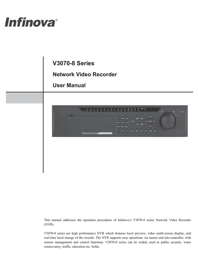
Infinova V3062 Series Installation instructions

V3062 Series
Embedded Network Digital Video Recorder
Installation/Operation Instructions
This manual is applicable for the installation and operation of Infinova V3062 series Embedded
Network Digital Video Recorders.
Infinova V3062 Series DVR integrates advanced video compression and storage technologies, with 4-ch
analog video inputs, 4-ch full H.264 video encoding and G711 audio encoding. It supports synchronal
audio inputs, USB2.0 high-speed backup, and mouse operations.
The functional DVR can be widely used in security surveillance for small shops, band ATMs, public
security, telecommunication, traffic, and education etc.


Notice
Copyright Statement
This manual may not be reproduced in any form or by any means to create any derivative such as translation, transformation, or adaptation
without the prior written permission of Infinova.
Infinova reserves the right to change this manual and the specifications without prior notice. The most recent product specifications and
user documentation for all Infinova products are available on our website www.infinova.com
Trademarks
Infinova
®is a trademark of Infinova.
Copyright © 1993-2013 Infinova. All rights reserved
All other trademarks that may appear belong to their respective proprietors.
FCC Warning
V3062 series Network Digital Video Recorders all comply with Part 15 of the FCC rules.
Operation is subject to the following two conditions.
yThis device may not cause harmful interference.
yThis device must accept any interference received, including interference that may cause undesired operation.
V3062 series Network Digital Video Recorders have been tested and found to comply with the limits for Class A digital device, pursuant to
Part 15 of the FCC rules. These limits are designed to provide reasonable protection against harmful interference when the equipment is
operated in a residential environment. This equipment generates, uses, and can radiate radio frequency energy and, if not installed and used
in accordance with the instructions, may cause harmful interference to radio communications. However, there is no guarantee that
interference will not occur in a particular installation.

Read this manual carefully before installation. This manual should be saved for future use.
Important Safety Instructions and Warnings
zElectronic devices must be kept away from water, fire or high magnetic radiation.
zClean with a dry cloth.
zProvide adequate ventilation.
zUnplug the power supply when the device is not to be used for an extended period of time.
zOnly use components and parts recommended by manufacturer.
zPosition power source and related wires to assure they will be kept away from ground and access way.
zRefer all service matters to qualified personnel.
zSave product packaging to ensure availability of proper shipping containers for future transportation.
Indicates that the un-insulated components within the product may carry a voltage harmful to humans.
Indicates operations that should be conducted in strict compliance with instructions and guidelines contained in this manual.
Use at altitude below 2000m.
Use in nontropical areas.
Warning: To avoid risk of fire and electric shock, keep indoor products away from rain and moisture!
Related Documentations
y<V3062 Series Embedded DVR Quick Operation Guide>

Install Environment and Notes
Install Environment
zWorking temperature of DVR: 0ć~50ćˈstorage temperature -20ć~70ć.
zDVR should be placed flatly during installation or operation, avoid slantways or inversed placement.
zAvoid placement and installation in high temperature and high humidity.
zFor better heat-radiation, cooling fan is designed inside the DVR. Further, install the device in the place with good ventilation and
dust-free condition.
zTo ensure a better heat-radiation, the distance between the DVR back panel and the other devices or the wall should be more than 6CM.
zDo not move DVR in the place with sharp temperature contrast to avoid condensation inside the device which will shorten the lifespan
of the machine.
zInstall the thunder protection devices for the DVR applied in thundery areas to prevent the thunder-caused hardware damages.
Notes
zDon't touch the power switch or DVR with wet hands or wet stuff.
zAfter the installation, to avoid the interference of the video/audio signals and the damages caused by the static electricity, please make
sure that DVR and the housing are well grounded (refer to the grounding interface on the rear panel).
zMake sure that the voltage of the power supply is stable.
zAvoid splashing down the liquid or metal on DVR, which may cause short circuit even fire inside DVR.
zInstall the harddisk correctly before use, or else, you can't make any record operation.
zThe dust of the mainboard may cause short circuit after being damped, therefore, to maintain a long life usage of the device, please clean
the mainboard, inserts, housing and cooling fan regularly.
zTry not to apply TV set at the local video output interface (VIDEO OUT), otherwise, the output circuit of the DVR (VIDEO OUT) is apt
to damages.
zWhen shut down the DVR, do not turn off the power switch directly. Please firstly close the current recording, then complete the
software shut down via menu, and at last close the power switch on the rear panel. In this way, the possible hardware damages are
avoided.
zDVR is able to auto-check the harddisk, when a new harddisk without formatting or a nonsupport file system of the harddisk, system
will alarm to user, the record could be taken only after the harddisk is formatted. If the harddisk has been used before and meanwhile it
has subareas record, please delete the subareas on PC first, and then format the harddisk in DVR. Otherwise, the normal record will be
influenced.
zDo not conduct the hardware hot-swapping operation with electricity. (Except the hardware supporting hot-swapping)
zChange the damaged harddisk to insure the integrality of the record data (The information of the harddisk error is in the log)
zIt's better to use the recommended HDDs only. Please visit below link for the list of the HDDs recommended by Infinova:
http://www.infinova.com/admin/product/PDF/ListofRecommendedDVRBackupDevices.pdf.


Table of Contents
Chapter 1 System Overview ......................................................... 1
1.1 Product Description ..............................................................1
1.2 Front Panel Introduction .......................................................2
1.3 Remote Controller Introduction ............................................4
Chapter 2 Installation and Connection........................................ 6
2.1 Counter-check Device and Accessories.................................6
2.2 Install Hard Disk................................................................... 6
2.3 Rear Panel Introduction ........................................................7
2.4 Alarm Input/output Connection Method Introduction...........8
2.5 Ethernet Connection Cable Making Method.........................8
2.6 RS-485 Pan/Tilt Decoder ...................................................... 9
Chapter 3 System Menu Introduction ......................................... 9
3.1 Menu Operation ....................................................................9
3.1.1 Cursor Switching.........................................................10
3.1.2 Option Box..................................................................10
3.1.3 List Box.......................................................................10
3.1.4 Editing Box .................................................................10
3.1.5 Buttons ........................................................................ 11
3.1.6 Input Method............................................................... 11
3.1.7 Statusbar Introduction ................................................. 11
3.2 Menu Structure....................................................................12
Chapter 4 Main Functions Introduction.................................... 13
4.1 Turn on DVR ......................................................................13
4.2 User Login and Authority ...................................................13
4.2.1 User Login...................................................................13
4.2.2 User Authority.............................................................14
4.3 Preview ...............................................................................14
4.3.1 Switch Preview Modes................................................ 14
4.3.2 Preview Setting ...........................................................15
4.4 PTZ Control........................................................................15
4.4.1 PTZ Parameters Setting............................................... 15
4.4.2 PTZ Control ................................................................ 16
4.4.3 Set and Call Preset....................................................... 16
4.4.4 Set and Call Pattern..................................................... 16
4.5 Alarm.................................................................................. 16
4.5.1 Channel Alarm ............................................................ 16
4.5.2 Alarm Input ................................................................. 18
4.5.3 Exception Alarm.......................................................... 19
4.6 Alarm Management............................................................. 19
4.7 Recording............................................................................ 19
4.7.1 Manual Recording....................................................... 19
4.7.2 Scheduled Recording................................................... 20
4.7.3 Alarm Recording ......................................................... 21
4.8 Playback.............................................................................. 21
4.9 Power Off............................................................................ 22
Chapter 5 Other Settings ............................................................ 23
5.1 Preview Settings ................................................................. 23
5.2 Network Settings ................................................................ 24
5.3 Serial Port Settings..............................................................25
5.4 User Management............................................................... 25
5.5 System Settings................................................................... 26
5.5.1 Display Settings .......................................................... 26
5.5.2 Time Settings............................................................... 27
5.5.3 Log Management ........................................................ 27
5.5.4 Hard Disk Management .............................................. 28
5.5.5 Data Backup................................................................ 28
5.5.6 Advanced Settings....................................................... 29
5.5.7 General Channel Settings............................................ 29
5.5.8 Bi-directional Audio Talk-back ................................... 29


1
Chapter 1 System Overview
1.1 Product Description
Infinova's V3062 series new-generation network digital video
recorder is integrated multiple advanced information technologies
and manufactured under strict quality control system. The DVR
supports 4-channel analog video inputs and 4-channel full D1
H.264 video compression and G.711 audio compression, providing
synchronous video and audio input. USB2.0 high speed backup and
mouse device operations are also supported. V3062 series DVR is
ideal for the monitoring of small shops, ATM banks, and can be
widely adopted in fields like public security, telecom, traffic, power
station, education etc.
Features
yEmploy high performance Power PC structure and embedded
Linux operating system
yPAL/NTSC format video signal supported
yH.264 video compression
yG.711A audio compression
y4-ch full D1 encoding, each channel supports dual streams
yMaximum support 4-ch D1 video synchronal playback
yVideo encoding parameters for each channel is independent
and adjustable, including resolution, frame rate, bit rate, image
quality etc.
ySupport compound stream and video stream encoding, with
audio and video synchronal in compound stream encoding
y1-ch HD VGA and CVBS main/auxiliary output, VGA video
resolution: 800×600 @ 60Hz, 1024×768 @ 60Hz, 1280×1024
@ 60Hz, 1366×768 @ 60Hz, 1440×900 @ 60Hz, 800×600 @
75Hz, 1024×768 @ 75Hz
ySupport 1/4 screen preview, with sequence of channels
adjustable
ySupport live view group switch, manual switch and automatic
cycle, the interval of automatic cycle can be adjusted
ySupport playback zoom in electronically; mouse clicking pan,
zoom area
yScreen out designated channel
ySupport motion detection, video loss, video mask detection
and video privacy mask
yCompatible with multiple control protocols of leading encoder,
support preset and pattern
ySupport zoom-in function by mouse operation when control
Infinova second generation domes
yMaximum 2 SATA hard disks supported, maximum 2TB for
each hard disk
yHard disk sleep
yThe exported file formats are compatible with Windows. Hard
disk space pre-allocation technology is adopted to avoid disk
patch
yRecording activation mode including manual, scheduled,
alarm triggered
ySwitch signal input alarm/motion detection pre-record and
post-record functionality
y48 recording time sections per day, and recording activation
mode can be varied for each time section
ySearch recording files via time, channel number and recording
type; forward and backward play modes are available
ySupport playback on two monitors
yUSB2.0 port for external hard disks and mouse devices
y4 alarm inputs and 2 relay outputs
ySupport video loss, motion detection, video mask, illegal visit,
network break, hard disk full, and IP conflict alarms,
associating to multiple alarm outputs
yAudible warning, uploading to control center, activating alarm
output etc. Optional in alarm. And alarm preview is supported
ySelf-recovery when system run abnormally
ySupport operations via front panel keys, mouse, remote
controller etc.
yTwo levels access management
ySupport password authentication logon
yLog and search function
yLocal storage
ySupport SNMP
yTwo access modes: local and network
yLocal or remote control of PTZ systems or domes
y1 10M/100M/1000M self-adaptive network port
yBuilt-in TCP/IP, UDP, PPPoE, DHCP, etc. network protocols,
ADSL (PPPoE) dialing
ySupport remote search, recording, transmission and live
monitoring can be performed simultaneously while searching
ySupport intercom
yPerform almost all functions via client software, including live
view the video of any channel, check device status, set system
parameters, PTZ control, remote search of recording files,
playback and download, system upgrade, reboot and shutdown
yUpdate software through USB
yPower off protection, self-recovery while powering on

2
1.2 Front Panel Introduction
Figure 1-1 Front panel
No. Name Type Description
1CH1~CH4
Channel
status
indicator
Channel 1~4 status indication, "Green" indicates recording is ongoing, "red" indicates
net transfer is ongoing, "orange" indicates both recording and net transfer are ongoing
READY Status
indicator Green: DVR is ready to work
HDD Status
indicator Red flickering: hard disk is running
TX/RX Status
indicator Orange flickering: transmitting/receiving data
STATUS Status
indicator
Green: DVR is being controlled by remote controller;
Red: DVR is in PTZ control status (Note: the dome will be under menu controlled status
when it is controlled via GUI menu, not PTZ control status);
Orange: DVR is in PTZ control status and is being controlled by remote controller;
Off: Neither the DVR is in PTZ control status nor being controlled by remote controller
2
POWER Power
indicator
Green indicates the device is running, and Red indicates the DVR is powered but not in
work, grey of indicator represents the power switch on the DVR rear panel is off or the
power cord is plugged out.
3Number key
Ǐ0ǐ~Ǐ9ǐInput key
(1) Input information (Ǐ0ǐ~Ǐ9ǐ: including number, capital letters, lowercase letters,
symbols);
(2) Switch channel in “Preview” and “PTZ control” modes: input Ǐ1ǐto switch to the
channel 1, and so as the other channels.;
(3) Call up presets when used with the buttonǏPRSTǐ
ǏMENUǐFunction
key
(1) Switch from preview interface to menu operation interface;
(2) Turn on/off the sound in the operations of the front panel buttons (pressing for 3
seconds);
(3) Enable/disable the screen wiper in “PTZ control”;
(4) Display/hide the tool column in playback
4
ǏPLAYǐControl key (1) Switch from preview interface to video records searching interface
(2) In “PTZ control”, start the autopan. Press any of the dome control buttons (including
the directional buttons, ǏIRIS-ǐ, ǏIRIS+ǐ, ǏWIDEǐ, ǏTELEǐ, ǏPTZǐ, Ǐ⬄ǐ,

3
No. Name Type Description
Ǐ*ǐ, ǏMENUǐetc.) can stop the autopan
ǏRECǐControl key
(1) Switch from the preview interface to the record management interface
(2) In “PTZ control”, call presets. Input 3 digits number combination keys after pressing
this key
ǏIRIS+ǐControl key
(1) Open iris in PTZ control status
(2) Delete the characters before cursor in editing status
(3) Display/Hide cursor (blue grid) in setting "Mask/Video Mask Alarm/Motion
Detection Area.(Need to be used together with ǏENTǐkey and direction keys)
ǏIRIS-ǐControl key (1) Close iris in PTZ control status
(2) Quick enter to "PTZ control" mode, the function is same as ǏPTZǐkey
Ǐˆǐ Control key
(1) Switch input methods (numeral, letter and symbol)
(2) Reduce focus in PTZ control status
(3) Set the full screen as setting area in "Mask/Video mask alarm/Motion detection"
setting
Ǐ⬄ǐ Control key
(1) Switch among multiple-screen (1/4 screen) display modes in preview interface
(2) Increase focus in PTZ control status
(3) Clear all setting area in "Mask/Video mask alarm/Motion detection" setting
ǏPRSTǐControl key In PTZ control status, call up presets. Input 3 digits number combination keys after
pressing this key
ǏWIDEǐControl key
(1) Zoom out in PTZ Control
(2) Switch among tabs in submenu
(3) Hide/Display lower status bar in preview interface
ǏTELEǐControl key Zoom in in PTZ control
ǏPTZǐControl key (1) Quick enter to "PTZ control" mode
(2) Close iris in PTZ control, same as ǏIRIS-ǐkey
Direction keys Control key
(1) ǏǐǏǐkeys: Select options of right key menu and list box; Ǐǐ,Ǐǐ,Ǐǐ,
Ǐǐkeys: Select options in main menu; ǏǐǏǐǏǐǏǐkeys: Select options
in submenus
(2) Direction control in PTZ control. Quick press Ǐǐkey twice to decrease speed, and
increase speed by quick pressing Ǐǐkey twice; Total 8 different levels of speed is
available and adjustable
(3) Adjust the position of the selected OSD. Set "Arm Time/Mask/Video Mask
Alarm/Motion Detection Area Size" when is used together with ǏENTǐkey
(4) Press ǏǐǏǐkey to move the position of cursor when input message
(5) Press ǏǐǏǐkey to move forward or reverse the videos by 30s increments in
playback, and pressǏƷǐǏǐto play fast forward or slow forward
ǏENTǐControl key
(1) confirm current operation (enter the sub-item or confirm the current operation)
(2) Exit from the “PTZ control” mode
(3) Start/Finish an area setting in "Mask/Video mask alarm/Motion detection" setting.
(Combine with direction keys to set the selected area size)
(4) Pause/play the video playing in playback
5
ǏESCǐControl key (1) Return to previous menu

4
No. Name Type Description
(2) Quit from PTZ control mode
(3) Quit from record playback mode
6Power Switch Control key Device On/Off (pressing at least 3 seconds when turn off the devices)
7Infrared
Receiver Make the controller pointed at the infrared receiver (Note: Do not cover the receiver part
when use remote controller)
1.3 Remote Controller Introduction
No. Name Full Name Type Description
1 Power Switch Control key Power switch of DVR (Press at least 3 seconds when turn off the DVR)
2 DEV Device Control key Select DVR to be controlled. Operation method: DEV key>Device No.>
ENTER key
3 0~9 Number Key Input key The function is the same with the number keys in front panel
4 EDIT Edit Control key Delete the characters before the cursor
5 A Input Method Control key
(1) Switch among input methods (numeric, English letters and symbol)
(2) Set the full screen as setting area in "Mask/Video mask
alarm/Motion detection" setting
6 SYS System
Information Function key Check the system information
7 ESC Exit Function key The function is the same with ǏESCǐkey on front panel
8 MENU Main Menu Function key The function is the same with ǏMENUǐkey on front panel

5
9 VOIP
/MON
Voice Intercom/
Auxiliary
Output
Function key Reserved
10
Direction keys
and
Confirmation
Key
Control key The function is the same with the direction keys and ǏENTǐkey on front
panel
11 IRIS Iris Control key Open/Close iris in PTZ control
12 FOCUS Focus Control key Increase/Decrease focus in PTZ control
13 F1 F1 Function key Switch monitor
14 REC Video Record Function key
(1) Switch from the preview interface to the recording management
interface
(2) Call up presets in PTZ control, same as ǏPRSTǐon front panel
15 PLAY Play Video Function key Same as ǏPLAYǐon front panel
16 ZOOM Zoom in/out Control key
Zoom in/out in PTZ control;
Note: Zoom-
(1) Switch among tabs on submenu
(2) Hide/Display lower status bar in preview interface
17 PTZ PTZ Control key Same as ǏPTZǐon front panel
18 PREV Multiple-screen Control key
(1) Switch multiple-screen (1, 4 screens) display modes in preview
interface
(2) Clear all setting area in "Mask/Video mask alarm/Motion detection"
setting
19 Reserved
Remote controller installation and use method
1. Load battery
(1) Open the cover of the battery cabinet;
(2) Load 2 No.7 batteries, ensure the polarity is correct;
(3) Close the battery cabinet.
2. Start using remote controller
After the DVR has been started up well, press the DEV key on
the remote controller, and then input the device number of the
DVR (the default device No. is 1, it can be modified in "Display").
Press ENTER key, if the indicator on the controller turns green, it
means that the DVR is connected and can be controlled by remote
controller.
Note: Device number should be 1 to 127.
3. Stop using remote controller
Press DEV key when the DVR is being controlled, the status
indicator will turn off, and then the remote controller stops to
control the DVR.
4. Shutdown DVR via remote controller
Press Switch key at least 3 seconds to turn off the DVR when it's
being controlled by controller.
In the preview mode a login box will pop up if password
protection is enabled. Users must select the user name and input a
correct password, and enter to "Shutdown" dialog box to select
"Confirm" to turn off the DVR.
Note: Do not turn off the power switch on the rear panel before
the shutting indicator in front panel turns red.
In the menu mode, press the power switch key for a few seconds,
there will be the "shutdown" dialog box if the user has authority
to operate the "System Management", and then the user can select
"Confirm" to shutdown the DVR. If the user doesn't have the
authority on "System Management", the user can not turn off the
DVR normally.
5. Troubleshooting for remote controller
If the remote controller doesn't work normally:
yReduce the operating distance between DVR and controller
yAim the controller at the infrared receiver of the DVR
yCheck the polarity of the battery loaded
yChange the used battery and load new battery
yCheck if the sensor of the controller is obstructed
yCheck if fluorescence lamp is being nearby
Note: Please replace the controller if it doesn't work after the
above operations. It should be the infrared receiver problem if the
new controller doesn't work either. Please contact after-sale
service engineer timely.

6
Chapter 2 Installation and Connection
Note: Make sure the power supply cable is disconnected before
connecting DVR with other device.
2.1 Counter-check Device and Accessories
In the package, there should be the following items:
1. 1 V3062 DVR
2. 1 V3062 Installation and Operation Manual
3. 1 V3062 Quick Operation Guide
4. 1 COC
5. 1 CD (client software)
6. 1 remote controller
7. 1 USB mouse
8. 1 Power cord
9. SATA data cable
10. Screws
11. Power adapter
12. 1 Hard disk power cord
Note: The accessories are different upon models of V3062, please
subject to the packing list. Please contact dealer timely for damaged
or missing parts.
2.2 Install Hard Disk
1. Installation precaution
Disassembly of the housing and installation of hard disks must be
performed by professionals. Before installation of hard disks, please
calculate total capacity required by each DVR according to video
recording parameters.
2. Installation Tool
One Philips head screw driver.
3. Install Hard Disk
1. Open the housing
2. Install the hard disk. (2 SATA hard disk ports are available for
V3062 DVR)
3. Fix the hard disk on the hard disk rack base
4. Install and fix the rack to DVR with screw
5. Connect the hard disk data cable
6. Connect the hard disk power cord
7. Close and fix the housing with screw
Reference:
Formula to calculate total capacity needed for DVR
Calculate total capacity needed by each DVR according to video
recording (video recording type and video file storage time).
Calculate formula:
1st Step: Calculate the capacity i
qneeded for one channel per hour
according the formula 1, unit: MByte.
Formula 1: 102436008 yuy ii dq
i
d: Bit rate, unit: Kbit/s
2nd Step: Calculate the capacity i
mfor one channel after fixing
recording time according to the formula 2, unit: MByte.
Formula 2: i
m= i
q×i
h×i
D
i
h: Recording time(hours) for each day; i
D: the number of day
that the video will be kept.
3rd Step: Calculate the total capacity T
qneeded in the setting time
for all channels of the DVR.
Formula 3:
¦
c
i
iT mq
1
C: the total number of channels of the DVR
Calculate the total capacity T
qfor alarm recording (including
motion detection recording) of all channels According to the
formula 4.
Formula 4:
¦
c
i
iT mq
1×a%
a%: Alarm occurring rate.

7
2.3 Rear Panel Introduction
1 3 5 6 7 8 9
42 10 11 12 13
Figure 2-1 Rear Panel
No. Item Description
1 ETHERNET PORT 1 10/100/1000Mbps self-adaptive Ethernet port for connection with network devices,
RJ45 connector.
2 USB PORT 2 standard USB 2.0 ports for connection with USB devices like mouse, U disk, mobile
disk etc. for data backup and mouse operations. Hot- swapping is supported.
3 AUDIO IN 4-ch audio inputs, 4 standard RCA interface
4 AUDIO OUT 1-ch audio output, standard RCA interface
5 LINE IN For intercom, 1-ch audio input, standard RCA interface to connect with audio input
devices (e.g. microphone)
6 VIDEO IN Standard BNC interface to connect with analog video device for 4-ch analog video inputs.
7 VIDEO OUT
Standard BNC interface to connect with monitor for 2-ch analog video outputs. VGA,
OUT1 and OUT2 video outputs are independent from each other, in which OUT1 and
VGA are for video signal output and menu display, and OUT2 for video signal output.
8 VGA Standard VGA interface to connect with VGA display device for video output and menu
display.
9 POWER SWITCH Power on/off
10 ALARM IN/OUT 4-ch alarm inputs (4-ch switch signal);
2-ch alarm outputs (2-ch switch signal)
11 RS-485 INTERFACE Connect with RS-485 serial device (such as Pan/Tilt encoder)
12 POWER SUPPLY 12VDC power supply
13 GROUNDING TERMINAL Grounding terminal of the DVR

8
2.4 Alarm Input/output Connection Method
Introduction
1. Alarm input interface introduction
Figure 2-2 Alarm input interface
G (GND): 1 "Alarm Input" GND ports, internally connected and
shared the GND with every alarm input device.
1-4: Connect with alarm input device, activated by normal
open/normal close electricity level, voltage range 0~5V.
The alarm input is switching value signal (main node) input. Refer
to the following diagram for the connection if the alarm input signal
isn't switching value signal, such as voltage signal.
Voltage
Output
Switching
Value Input
Alarm DVR
ALM+
ALM-
IN(n)
G
Relay
Figure 2-3 Alarm input connection method
Note:
(1) Normal Open (N.O.): Normally, the relay status is open. The
relay will close when it's shorted with ground, and the device
will generate alarm signals.
(2) Normal Close (N.C.): Normally, the relay status is closed. (The
relay is connected to ground). The device will generate alarm
signals when the relay is disconnected.
2. Alarm output interface introduction
G: "Alarm Output" GND port, every output port and the related
alarm output port in the left side are used together.
1-2: Connect with 2 alarm output devices respectively.
Refer to following diagram for connection of alarm output.
DVR Alarm Output
Port DC Load
Indicator
J1400
1
G
+5V
Alarm Circuit
Figure 2-4 Alarm output DC load connection
DVR Alarm Output
Port AC or DC Load
J1400
1
G
+5V
Relay
DC/AC
Figure 2-5 Alarm output relay connection
As shown in above diagram, the internal alarm circuit makes 1/2
output port connected with the corresponding G when there's no
alarm. And 1/2 output port will contact with +5V node when there's
alarm, which will activate the indicator or audible alarm.
There is a jumper J1400 on the mainboard which is closed in
factory default setting. When open, it is used to avoid damage to the
device if the external alarm circuit is shorted. It shall be closed
normally.
There're 2 alarm indicators on the mainboard, which are related to
the 2 alarm outputs respectively, and will illuminate if there's alarm.
Note:
(1) The 1/2 output port supply +5V voltage when there's alarm,
which is supplied to the DC load with rating voltage less than
+5V only, and current limitation protection circuit should be
added. It must use relay when connect with high voltage AC or
DC load, or the alarm function will be invalid, what's more,
may have damage to the device. It's recommended to use relay
connection (refer to Figure 2-6).
(2) Make sure the 1/2 output ports are not shorted to the
corresponding G, or the device will be damaged. Disconnect
the jumper cap before finishing connection of circuit and
confirm no short-circuit between 1/2 output ports and
corresponding G when connect with external alarm circuit.
2.5 Ethernet Connection Cable Making Method
1. Material and tool
A twisted pair cable (8 cores, length depends on the actual demand,
but less than 100m), 2 standard RJ45 connectors, 1 special tool for
RJ45.
Suggestion: Use a network cable test tool to test the cable made.
2. Pin definition
The pin sequence of RJ45 as follows:
Figure 2-6 RJ 45 connector

9
Prepare the network cable based on the demand, there're two
conditions as follows:
(1) Follow below method to make the network cable when DVR is
connected with HUB or the network switcher:
Figure 2-7 Parallelism of direct cable
(2) Follow below method to make the twisted network cable when
DVR is directly connected with a client terminal like PC.
Figure 2-8 Parallelism of cross cable
2.6 RS-485 Pan/Tilt Decoder
Connection introduction
Green terminal block pin connector is provided with the device for
connecting the signal cable, and the specific steps are as follows:
1. Plug out the RS-485 green block pin connector on the DVR.
2. Loose the screws of the block pin connector with small Phillips
screwdriver, and place the RS-485 control line under the leaf spring
in the connector, and then tighten the screws.
3. Place the block pin connector that connected with RS-485 control
line to the corresponding green terminal block pin socket.
Chapter 3 System Menu Introduction
Note: V3062 series DVR could be operated through front panel,
USB mouse and remote controller. For mouse operation, there's no
introduction here for it is generally the same as windows system.
This manual mainly focuses on the introduction of the operation via
front panel.
3.1 Menu Operation
V3062 series DVR has three levels of menu. The first level of menu
is shown in Figure 3-1.
Figure 3-1
Change the options by ǏǐǏǐǏǐǏǐkeys on front panel.
The icon will be highlighted when it's selected. For example, the
"Alarm" icon is selected, and it becomes bigger with light blue
shadow at two sides, as shown in Figure 3-2.
Figure 3-2
Each level of menu has a unique number related to it, as shown
below:

10
1
Channel
2
Preview
3
Alarm
4
Record
5
Network
6
Playback
7
PTZ/COM
8
User
9
System
Press ǏENTǐkey or the corresponding number key to enter the
submenu when a menu icon is selected. For example, "Channel"
icon is selected, pressǏENTǐkey orǏ1ǐkey to enter the submenu
of "Channel", as shown in Figure 3-3.
Figure 3-3
Each menu support various operations, below section will have
detailed introduction on operations of the common used control and
input method.
3.1.1 Cursor Switching
The cursor can be switched via ǏWIDEǐ,Ǐǐ,Ǐǐ,Ǐǐ
andǏǐkeys, as shown in Figure 3-3.
Users could switch the options via ǏWIDEǐkey. For example,
users could switch among "General Settings" and "Advanced
Settings" in the interface as shown in Figure 3-3.
Users can select the related parameters by Ǐǐ,Ǐǐ,Ǐǐand
Ǐǐkeys after enter to "General Settings". After selecting
"Channel" parameter, users can press ǏENTǐkey to call out the
drop-down list to select the desired parameter, as shown in Figure
3-5. Press ǏENTǐkey to confirm the selection. Then pressǏǐ,
Ǐǐ,ǏǐandǏǐkeys to enter the next parameter in the
interface.
3.1.2 Option Box
A "9" in the check box indicates the option is selected. Move the
cursor to the desired option via Ǐǐ,Ǐǐ,ǏǐandǏǐ
keys, then pressǏENTǐto select it, and it cancel the selection if the
option is selected when press ǏENTǐkey. For example, the cursor
moves to "Video Loss Alarm" option, press ǏENTǐkey to select or
cancel selection, as shown in Figure 3-4.
Figure 3-4
3.1.3 List Box
When there're 2 or above options, and only 1 option can be selected,
first pressǏENTǐto call out the list box, and then select the desired
option by pressingǏǐandǏǐkey, at last press ǏENTǐto
confirm the selection. For example, in the Figure 3-3, the "Channel"
parameter has 4 options. Firstly pressǏENTǐkey to call out the list
box, then select 01 channel by pressing Ǐǐand Ǐǐkey, as
shown in Figure 3-5.
Figure 3-5
3.1.4 Editing Box
A rectangle box is available for input of message. Users could
select the desired option to be edited by pressingǏǐ,Ǐǐ,Ǐǐ
andǏǐkeys, and pressǏENTǐkey to edit status, then input

11
message.
Users could perform the following operations in the edit status:
(1) Delete the characters before the cursor by pressing ǏIRIS+ǐ
key;
(2) Switch among small/capital letter, symbols and number by
pressingǏ*ǐkey;
(3) Move the cursor position by pressing ǏǐandǏǐkey;
(4) Save temporarily the current input message by pressing
ǏENTǐ.
Note: The input method of "Date/Time Edit Box" is the same with
"Edit Box". When operate via mouse, the input of Year/Month/Date
need to press drop-down arrow of "Date/Time Edit Box" to call out
the calendar, and select the desired date or select the date by rolling
the roller. Hour/minute can be set by rolling the roller.
3.1.5 Buttons
The buttons are used to perform a specific function or to enter a
submenu.
There're 16 function buttons as follows:
"Save": Save the current parameter settings, have message prompt
when there's error.
"Exit": Cancel current operation and return to previous menu.
"Copy": Copy parameters.
"Clear All": Clear all editing message in the current menu.
"Clear": Clear all selected message in the current menu.
"Select All": Select all available options in current menu.
"Cancel": Cancel all the selection of the options in current menu.
"Search": Search the content matching with the setting.
"Refresh": Refresh the data in the list.
"Play": Play the file selected in the current menu.
"Backup": Copy the message selected to the designated file.
"Default": Set the parameters as default setting.
"Apply": Configure corresponding setting based on the current
parameter.
"Backward ": Return to previous operation.
"Forward": Go to next operation.
"Start Backup": Start backup of the message selected.
Note: The "Save" button is not usable in default, and it will be
enabled when there's modification of parameters. The button will be
inactive after saving. Except "Save" button, the other buttons are
not usable if the color is gray, and the buttons will be enabled when
there're some other operations conducted, or the function is not
usable. Please contact to manufacturer if need to customize the
function.
3.1.6 Input Method
In the menu operation interface, enter the edit status of the editing
box, a status as shown in Figure 3-6 will appear at the right side,
then users can input small letter in the editing box by the number
keys on the front panel.
Figure 3-6
Besides small letters, users can input capital letters, symbols and
number, the operation as follows:
1. Input capital letters and number
PressǏ*ǐkey to switch the input method if users need to input
capital letter or number, as shown in Figure 3-7 and Figure 3-8.
Figure 3-7
Figure 3-8
2. Input symbols
If need to input symbols, switch the input method to the status as
shown in Figure 3-9 by pressing Ǐ*ǐkey. Then a bar will appear
on the editing box (the symbols in the bar is yellow color, as shown
in Figure 3-10). Select the desired symbols by pressing number
keys or by mouse, as shown in Figure 3-11. Click the next page
button at the right side of the bar or pressǏǐkey to next page if
there's no the desired symbol in the current page.
Figure 3-9
Figure 3-10
Figure 3-11
Note:
(1) Some editing boxes allow number input only. Front panel
number keys can only input numbers.
(2) For the letters combined in one key, press the key one time to
input the first letter, press continuously twice to input the second
letter, and so on.ǏǐandǏǐkeys are used to turn pages.
Operation hint: In this manual, we use different Ǐkey nameǐto
stand for the keys in front panel. For example, ǏENTǐfor confirm
key, ǏHDDǐindicator for the hard disks indicators. "Setting name"
indicates the parameter setting option in the menu interface, for
example, "Save" indicates save the parameters.
3.1.7 Statusbar Introduction
Alarm input: icon , to display the current alarm type. If there
are different alarm types, all types will be displayed in turn.
User name: icon , to display the user name of current
logon user.

12
Monitor: icon , to display the current main output monitor.
If the main output is VGA, then VGA, BNC1, BNC2 are displayed
by monitor1, monitor2, monitor3 correspondently. If the main
output is BNC, then BNC1, VGA, BNC2 are displayed by monitor1,
monitor2, monitor3 correspondently. The monitor sequence is a
little bit different from that in the section 4.3.2 Preview Settings, for
here it is mainly to indicate the main output type.
Data and time: icon , to display the current date,
time, and week.
3.2 Menu Structure
The different levels (3 levels) of menu structure and function as
follows:
First Level Second Level Third Level
Channel
Mask
Area Settings
Image Parameters
Contrast,
Brightness,
Hue, Saturation
Name
Time
Date Format
Display/Hide Week
OSD1
OSD2
Channel name
Time, Week
General
Settings
OSD Position OSD1,OSD2
position adjust
Channel
Schedule Week, Time
Video
Loss
Alarm Output
Audible
Warning,
Control Center,
Alarm Preview
and 2 Alarm
Outputs
Sensitivity
Area
Schedule Week, Time
Video
Mask
Alarm Output
Audible
Warning,
Control Center,
Alarm Preview
and 2 Alarm
Outputs
Sensitivity
Area
Schedule Week, Time
Video
Motion
Detection Linkage
Recording, PTZ
control,
Audible
Warning,
Control Center,
Alarm Preview
and 2 Alarm
Outputs
Channel
Advanced
Settings
Copy to
Preview
Monitor, Open/Close video preview,
Preview Switching Time, Open/Close
Alarm Preview, Alarm Preview Switching
Time, Preview Mode
Alarm Channel Status
Alarm Input
Alarm
Status
Video Loss, No Alarm,
Motion Detection, Mask
Alarm and Input Alarm
Status Mark
Alarm Input Choice,
Name Setting, Type
Schedule Week, Time
Linkage
Recording, PTZ
control,
Audible
Warning,
Control Center,
Alarm Preview
and 2 Alarm
Outputs
Alarm
Input
Copy to
Alarm Output
Delay Time
Schedule Week, Time
Alarm
Output
Copy To
Type
Alarm
Abnormity Output
Settings
Audible
Warning,
Control
Center, and 2
Alarm Outputs
Status of 4 channels
Open/Close 4 channels
manual recording
Manual
Recording
No Video, Normal,
Manual Recording,
Scheduled Recording and
Alarm Recording Status
Mark
Channel, Pre-recording,
Post-recording, Frame
Rate, Code Stream, IP
Rate, Resolution, Quality,
Bit Rate Type,, Max Bit
Rate and Copy To
Week, Time
Recording Type
Recording
Recording
Settings
Recording Schedule
Scheduled
Recording,
Alarm
Recording,
Scheduled &
Alarm
Recording,
Color Mark
General
Settings
NIC, NIC Type and MAC
Address, IP Type, IP
Address, Subnet Mask,
Gateway, Port, Auto DNS
and DNS
Network
Advanced
Settings
HTTP Port, SNMP Port,
Alarm Center, Alarm Port,
NAS IP, NAS Path
Channel, Type, Start/End Time, Playback
Playback Search
Record file
display list,
playback
Table of contents
Other Infinova Network Hardware manuals
