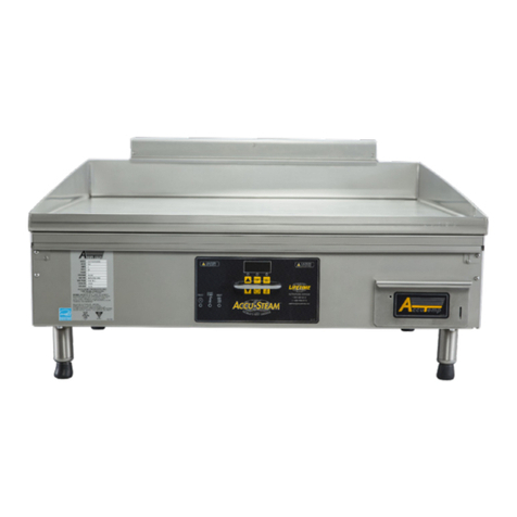
Infrico PG-60PV User manual

MANUAL DE INSTRUCCIONES PARA LA INSTALACIÓN,
EL USO Y MANTENIMIENTO
INSTALLATION AND ADJUSTEMENT INSTRUCTIONS
PLANCHAS DE GAS PARA USO COLECTIVO
GAS GRIDDLES
MODELOS:
MODELS:
PG-60PV; PG-75PV; PG-90PV
Versión:
Categoría: ll2H3+
Category: Version:
Tipo de instalación: A1
Instalation type:
Ed. / Rev.1
Leer atentamente el presente manual antes de instalar y utilizar el aparato.
Conservar este manual para futuras consultas.
Read this manual before installation and usage of the item.
Keep this manual for future consultation.
0370
Idioma:
Español
Language:
English

2
PG-60PV PG-75PV PG-90PV
ESPAÑOL
DECLARACIÓN DE CONFORMIDAD
El que suscribe:
Fabricante:
C.I.F.:
Domicilio:
Nº Fabricante: 08/147900
Declara, bajo su propia responsabilidad, que el producto:
Denominación: PLANCHAS DE GAS PARA USO COLECTIVO
Marca:
Serie: PG
Modelos PG-60PV; PG-75PV; PG-90PV
objeto de esta declaración es conforme con el modelo descrito en el Certificado de Examen CE de
Tipo nº , emitido por LGAI Technological Center (Applus) y, cumple las exigencias
esenciales establecidas en la Directiva para aparatos a gas (2009/142/CE).
Hecho en , el
Firmado por
Cargo Representante legal

3
TABLA DE DATOS TÉCNICOS
Gas
Presión
(mbar)
Qn (Hi) (kW)
Serie ECO-PV; ECO-ES
Qn (Hi) (kW)
Serie ECO-CD
Diámetro
inyector
(mm)
Reg. Aire
“A” (mm)
Nominal
Mínimo
Nominal
Mínimo
G20
20
4,1
2,63
4,0
2,2
1,45
1,5
G25
25
4,1
2,63
4,0
2,2
1,45
1,5
G30
28-30
4,1
2,63
4,2
2,31
1,00
2,5
G31
37
4,1
2,63
4,2
2,31
1,00
2,5
G30
30
4,1
2,63
4,2
2,31
1,00
2,5
G31
30
4,1
2,63
4,2
2,31
1,00
2,5
G30
50
4,2
2,7
4,3
2,36
0,90
2,5
G31
50
4,2
2,7
4,4
2,42
0,90
2,5
Modelo
Dimensiones (mm)
ancho x largo x alto
Nº quemadores
Qn (Hi) (kW)
G20 (20mbar)
G25 (25mbar)
G30 (28-30mbar)
G31 (37mbar)
G30 (30mbar)
G31 (30mbar)
G30 (50mbar)
G31 (50mbar)
PG-60PV
611x435x210
2
8,2
8,2
8,2
8,2
8,2
8,2
8,2
8,2
PG-75PV
773x435x210
2
8,7
8,7
8,7
8,7
8,7
8,7
8,9
8,9
PG-90PV
911x435x210
3
12,7
12,7
12,7
12,7
12,7
12,7
12,9
12,9
GASES, PRESIONES Y CATEGORÍAS DEFINIDAS

4
INSTRUCCIONES TÉCNICAS DE INSTALACIÓN Y REGULACIÓN PARA
EL INSTALADOR
PRECAUCIONES PREVIAS A LA INSTALACIÓN
Estas instrucciones sólo son válidas si el símbolo del país figura sobre el aparato. Si el símbolo
no aparece en el aparato, es necesario recurrir a las instrucciones técnicas que reunirán las
indicaciones necesarias para la adaptación del mismo a las condiciones de utilización del país.
Esta operación deberá ser efectuada por el personal autorizado por las reglamentaciones
vigentes sobre aparatos de gas o el que se requiera para cada país comunitario.
Los aparatos se instalarán en un lugar convenientemente ventilado de acuerdo con las
reglamentaciones en vigor, para impedir la formación de concentraciones inadmisibles de
sustancias nocivas para la salud en el local donde están instalados.
Los aparatos únicamente se instalarán sobre una superficie no combustible.
El aparato debe estar instalado a una distancia mínima de 1,5 m de cualquier material
combustible.
Las piezas protegidas por el fabricante y su mandatario NO deben manipularse por el
instalador y el usuario.
Se comprobará que el gas a utilizar corresponde con el que viene indicado en la etiqueta que
acompaña el aparato, y para el que ha sido calibrado por el fabricante.
Se comprobará que todos los elementos que componen el aparato se encuentran perfectamente
situados y que debido al transporte no han sufrido desajustes.
El aparato debe estar instalado a una distancia mínima de 200 mm de cualquier pared lateral y
trasera para proteger de las temperaturas próximas a los 80ºC que pueden alcanzar las paredes
del aparato.
Los aparatos no requieren una fijación especial.
IDENTIFICACIÓN DEL GAS DE SUMINISTRO Y EL GAS PARA EL QUE ESTÁ
PREPARADO EL APARATO
En la placa de características del aparato se pueden comprobar los siguientes datos técnicos del
aparato para realizar la instalación según el país de destino:
Categoría definida.
Gas correspondiente a la categoría.
Presión en función del gas.
Consumo nominal Qn(Hi).
Caudal.
Por otra parte es muy importante que el instalador conozca las características del gas de suministro
en el lugar de instalación consultándolo con la compañía de suministro y compruebe que el aparato
está preparado para tal instalación.
CONEXIÓN DEL APARATO A LA RED GENERAL DE SUMINISTRO DE GAS
Una vez realizada la comprobación de los datos del gas, el instalador se encargará de la conexión
del aparato a la red general de suministro de gas según las normas vigentes en el país de destino.
Las planchas están fabricadas para que puedan ser utilizadas con los gases correspondientes de los
países comunitarios de destino para los que han sido definidos.
El tubo flexible de alimentación de gas debe cumplir los requisitos nacionales en vigor y debe
examinarse periódicamente y sustituirse cuando sea necesario.
Las tomas de gas R1/2GM de las planchas se encuentran en la parte lateral izquierda.

5
CONTROL DE FUNCIONAMIENTO
· El aparato contiene las instrucciones necesarias para su uso.
· Controlar las fugas de gas en los aparatos.
· Controlar el encendido y la llama del quemador principal.
· Se recomienda al usuario que use el aparato siguiendo las instrucciones.
CONEXIÓN PARA LA EVACUACIÓN DE HUMOS
Según el método de evacuación, son aparatos de tipo A1, definidos como aparatos sin ventilador no
destinados a conectarse a un conducto, ni a un dispositivo de evacuación de los productos de la
combustión, hacia el exterior del local donde están instalados. Estos aparatos se instalarán con una
ventilación suficiente para impedir la formación de concentraciones inadmisibles de sustancias
nocivas para la salud en el local donde están instalados, tal y como se recomienda en el manual de
instrucciones de instalación.
El aparato debe colocarse bajo una campana extractora para asegurar la completa evacuación de
los gases de combustión y humos de los quemadores en la fase de cocción, evitándose así, la
concentración de dichos humos y gases producto de la combustión.
INSTRUCCIONES PARA LA CONVERSIÓN A DIFERENTES GASES
IMPORTANTE: La conversión del aparato a diferentes gases o presiones de alimentación deberá
hacerse por personal autorizado por la legislación vigente en el país de destino.
Todos los aparatos de MAINHO son sometidos a pruebas y ensayos, cada uno por separado, y
están acondicionados para el gas que indica la etiqueta adherida al aparato y al embalaje.
En caso de que fuera necesario adaptarlo a otro tipo de gas, debe inspeccionarse el kit adjunto que
va compuesto de los inyectores necesarios para cada tipo de gas siguiendo el presente libro de
instrucciones a fin de colocar el inyector adecuado y señalado al efecto.
Para la conversión a los diferentes gases hay que realizar una sustitución de los inyectores en los
quemadores.
SUSTITUCIÓN DEL INYECTOR DEL QUEMADOR
Para acceder cómodamente al inyector y al venturi del quemador, sólo es necesario retirar la
plancha superior.
Para proceder al cambio de inyectores según el gas a emplear se tendrá en cuenta los valores de los
diámetros del inyector indicados en las tablas de datos técnicos.
Una vez se desmonta el portainyector del conjunto de gas, se retira el inyector y se coloca el
nuevo.
Esta operación se realizará para todos los quemadores de que disponga el aparato.
REGULACIÓN DEL CAUDAL DE AIRE PRIMARIO PARA LA COMBUSTIÓN
El fabricante entrega el aparato con la regulación de aire ajustada al gas solicitado.
En caso de cambio de gas se realizará la regulación de aire aflojando el tornillo de fijación del
venturi y desplazándolo hasta que se tiene la distancia A de regulación según los valores de las
tablas de datos técnicos en función de los gases.
IMPORTANTE
· Una vez efectuado todas las operaciones de cambio de gas de la máquina se
debe cambiar la etiqueta indicativa del gas al que está preparado la máquina.
· Antes de poner en marcha el aparato debe procederse al análisis de fugas. A
tal fin se cubrirán las partes de unión y todas aquellas que hayan sido
manipuladas con agua jabonosa, espuma o detector de gases. En el caso de
apreciar una fuga se cerrará la llave de paso y se procederá a la reparación de
la parte afectada, volviendo a efectuar la misma operación hasta conseguir una
completa estanqueidad del circuito de gas.

6
CAUDAL DE EVACUACIÓN DE AIRE
El aparato será instalado en locales suficientemente ventilados, de acuerdo con la reglamentación
en vigor.
Según la norma EN 13410:2001, el caudal de evacuación de aire debe considerar, eventualmente,
los caudales de evacuación de aire requeridos para otros fines. La superficie y el número de
orificios se calculan a partir del valor más elevado de estos caudales de evacuación de aire.
Para calcular el caudal de evacuación de aire requerido se utilizará la siguiente fórmula:
Vtot= ∑QNB · L
Donde:
Vtot: caudal total de evacuación de aire requerido, en metros cúbicos por hora (m3/h)
∑QNB: consumo calorífico total de todos los aparatos en funcionamiento, en kilovatios (kW)
L: caudal unitario de evacuación de aire (> 10 m3/h)/Kw
PLACA DE CARACTERÍSTICAS
La placa de características está situada en la parte trasera de los aparatos.
ENGRASADO DE LAS VÁLVULAS
No engrasar la válvula en ningún caso, en caso de avería sustituir la válvula.
INSTRUCCIONES DE USO Y MANTENIMIENTO PARA EL USUARIO
PRECAUCIONES PREVIAS AL USO Y MANTENIMIENTO
· Este aparato es exclusivamente para uso profesional, y debe ser utilizado por personal
cualificado.
· Es conveniente llamar a un instalador cualificado para instalar el aparato, y llegado el caso, para
adaptarlo para utilizar otro tipo de gas.
· Las piezas protegidas por el fabricante y su mandatario NO deben manipularse por el instalador y
el usuario.
· Para realizar el mantenimiento, limpieza o reparaciones se debe cerrar la llave del gas.
· La modificación, eliminación o falta de mantenimiento de cualquier dispositivo del aparato, eleva
el riesgo de accidentes. Se recomienda efectuar verificaciones periódicas, de acuerdo con los
reglamentos en vigor en el país en que el aparato vaya a ser instalado.
· El fabricante no se hace responsable de los daños derivados del uso de la máquina con cualquier
modificación, eliminación, falta de mantenimiento de sus componentes realizada sin autorización
previa y expresa del fabricante.
· Es muy importante tener cuidado con las superficies calientes tales como la placa y las paredes
laterales y frontales del aparato, con el fin de evitar posibles quemaduras.
· Para realizar todas las operaciones de limpieza y mantenimiento es necesario dejar enfriar el
aparato.
OPERACIONES DE ENCENDIDO Y APAGADO DEL APARATO
ENCENDIDO
- Abrir el paso del gas de la red general de suministro.
- Presionar y girar el mando correspondiente a dicho quemador a la posición de llama pequeña.
- Presionar el pulsador del piezo-eléctrico hasta que se produzca la llama en el quemador.
- Mantener presionado el mando unos 15 segundos con el fin de que el bulbo del termopar tome la
temperatura suficiente y proceda a la apertura del gas mediante la válvula de seguridad que cada
quemador, y como consecuencia cada mando, lleva incorporado en el aparato.
- Regular la llama del quemador situando el mando en la posición deseada entre la llama grande y
pequeña.

7
APAGADO
1. Para realizar el APAGADO del aparato es suficiente con girar los mandos a la posición de
cerrado.
Con el fin de garantizar una máxima seguridad , se recomienda cerrar el paso del gas de la red
general de suministro.
Recomendaciones:
-Una vez encendido el aparato es conveniente vigilar la presión de servicio instalada ya que de
variar el caudal del gas sin efectuar regulación de aire primario podría originar una mala
combustión y, por consiguiente, emanaciones perjudicialies de gases quemados.
-Una vez encendido el aparato se vigilará que toda la línea de llamas que conforman el conjunto
del quemador esté perfectamente encendida. Si se observase algún orificio obturado se avisará al
servicio de mantenimiento autorizado por el fabricante para que se proceda convenientemente.
OPERACIONES DE LIMPIEZA, CONSERVACIÓN Y MANTENIMIENTO
El aparato debe ser limpiado regularmente para conservar su funcionalidad y su rendimiento. Se
recomienda una verificación anual del aparato para su correcto mantenimiento.
Para la limpieza ordinaria, seguir las siguientes operaciones:
· Antes de limpiar la plancha, verificar que el grifo del gas está cerrado, y que todos los
quemadores están cerrados. Dejar enfriar la máquina.
· No limpiar las superficies de acero inoxidable con detergentes abrasivos. Con cuidado quite las
incrustaciones de alimentos con la ayuda de una esponja.
· Evitar el estancamiento de los alimentos (especialmente los ácidos tales como sal, vinagre,
limón…) en las superficies de la cocina porque ayudan al deterioro de la máquina.
· Proceder a la limpieza de la parte de acero con agua tibia y con jabón, enjuague y seque bien. No
usar detergentes con cloro (lejía, ácido clorhídrico, etc.). Evitar la limpieza del acero con copos o
cepillos que podrían causar ralladas.
· No utilizar chorros directos de agua de alta presión debido a que el equipo podría sufrir daños en
los componentes interiores.
· No usar sustancias corrosivas (por ejemplo acido muriático, amoniaco, etc.) para pulir la plancha.
· Si la máquina no se utiliza en un largo periodo, untar con aceite las partes férricas y ventilar el
local.
· Las grasas residuales de la cocción de los alimentos se depositan en el cajón recolector situado en
la parte frontal de los aparatos. Éste, se retirará de la plancha tantas veces como sea necesario para
que no esté lleno de grasa, se limpiará con agua caliente y jabón y se colocará limpio nuevamente
en la plancha.
¡¡Cuidado!!
Si el dispositivo de regulación tiene problemas de maniobrabilidad, ponerse en contacto con un
asistente técnico autorizado por el fabricante (por ejemplo puede ser necesario engrasar el aparato
y es aconsejable controlarlo periódicamente; por esto es útil suscribir un contrato de asistencia que
prevea revisiones con una frecuencia precisa.
Todas las operaciones de manutención y reparación tienen que ser efectuadas por un personal
cualificado y autorizado por el fabricante o el vendedor.
Advertencia
El fabricante no se responsabiliza de modificaciones ajenas al origen del aparato.
El fabricante no se responsabiliza de las averías producidas por una mala utilización del aparato.
El fabricante no se responsabiliza del funcionamiento y calidad del aparato si ello lleva implícito la
inobservancia de las presentes INSTRUCCIONES DE USO.

8
ENGLISH
Inscriber:
Manufacturer:
C.I.F.:
Address:
Manufacturer Nº: 08/147900
Declares under their own responsibility that the product:
Denominated: GAS GRIDDLES
Brand:
Serie: PG
Models: PG-60PV; PG-75PV; PG-90PV
Object of this declaration, conform to the models described in CE Type Examination Certificate
number , awarded by the LGAI Technological Center (Applus), and complies with the
established demands in (2009/142/CE) Directive for gas appliances.
Made at
Signed by
Responsibility Legal representative
TECHNICAL DATA TABLE
Gas
Presure
(mbar)
Qn (Hi) (kW)
Serie ECO-PV; ECO-ES
Qn (Hi) (kW)
Serie ECO-CD
Injector
Diameter
(mm)
Air
regulation
“A” (mm)
Nominal
Minimum
Nominal
Minimum
G20
20
4,1
2,63
4,0
2,2
1,45
1,5
G25
25
4,1
2,63
4,0
2,2
1,45
1,5
G30
28-30
4,1
2,63
4,2
2,31
1,00
2,5
G31
37
4,1
2,63
4,2
2,31
1,00
2,5
G30
30
4,1
2,63
4,2
2,31
1,00
2,5
G31
30
4,1
2,63
4,2
2,31
1,00
2,5
G30
50
4,2
2,7
4,3
2,36
0,90
2,5
G31
50
4,2
2,7
4,4
2,42
0,90
2,5
Model
Dimensions (mm)
Long x wide x high
Nº Burner
Qn (Hi) (kW)
G20 (20mbar)
G25 (25mbar)
G30 (28-
30mbar)
G31 (37mbar)
G30 (30mbar)
G31 (30mbar)
G30 (50mbar)
G31 (50mbar)
PG-60PV
611x435x210
2
8,2
8,2
8,2
8,2
8,2
8,2
8,2
8,2
PG-75PV
773x435x210
2
8,7
8,7
8,7
8,7
8,7
8,7
8,9
8,9
PG-90PV
911x435x210
3
12,7
12,7
12,7
12,7
12,7
12,7
12,9
12,9

9
GAS, PRESSURES AND DEFINED CATEGORIES
INSTALLATION AND ADJUSTEMENT INSTRUCTIONS FOR THE
INSTALLER
PRE INSTALLATION PRECAUTIONS
These instructions are only valid if the country symbol appears on the appliance. If the symbol
does not appear on the appliance, it is necessary to refer to the technical instructions that
contain the necessary indications to adapt the appliance to the conditions of use of the country.
This operation must be undertaken by personnel authorized to do so by the regulations in force
regarding or by those regulations in force in each European Community country.
The appliance must only be installed in places with sufficient ventilation to stop the
accumulation of inadmissible concentrations of noxious substances in the area where they are
installed.
The appliances must only be installed on non-flammable surfaces.
The appliance must be installed at least 1.5 m distant from any other flammable material.
The parts that have been protected by the manufacturer MUST NOT BE MANIPULATED by
the installer and/or the user.
Check the gas type as indicated on the appliance characteristics plate and to which the
appliance has been calibrated by the manufacturer must correspond to the gas to be used.
The appliance must be checked before installation and verify that it has not suffered any
damage or adjustments altered during the shipment.
The appliance must be installed at least 200 mm from any lateral back wall to protect them
from the temperatures close to 80º that the appliance sides and back can reach.
The cooking plate could arrive to 300ºC degrees maximum.
The appliance doesn’t need any special fix.
GAS SUPPLY AND THE APPLIANCE GAS TYPE IDENTIFICATION
In the appliance technical data sheet can be found he following technical dates to carry out
installation according to the destined country:

10
Defined category.
Gas corresponding to the category.
Pressure regarding the gas.
Nominal consumption Qn(Hi).
Flow.
On the other hand, it is very important that the installer knows the gas supply characteristics where
the appliance is to be installed by consulting the supply company and checking that the appliance
is prepared for such installation.
CONNECTING THE APPLIANCE TO THE MAIN GAS SUPPLY
Once the gas dates has been checked, the installer can connect the appliance to the main gas
supply, according to the regulation in force in the destined country. The grill has been
manufactured to be used with the gas of community destined countries. The flexible tube from the
main supply to the appliance inlet must fulfill the national requirement in force and must be
checked periodically and replace it when it will be necessary.
The griddles have the gas inlet 1/2” placed in the left side.
PERFORMANCE CONTROL
·The appliance has the necessary instructions for your use
· Control the gas escapes of the appliances.
· Check the ignition and the main burner flame.
· We recommend the user to use the appliance as the instructions.
CONNECTION FOR THE REMOVAL OF VAPOURS
As the removal method, there are appliances of A1type, defined as appliances without ventilator
not destined to connect to any conduct, neither a removal combustion products dispositive to the
outside where are installed. These appliances will be installed with an enough ventilation to
prevent the non admissible concentration of harmful substance for the health in the local where be
installed as recommend in the installations instructions manual.
The appliance must be installed under extractor hood to secure the complete gas combustion and
burners fumes evacuation in cooking phase, avoiding the concentrations of the fumes and
combustion gases.
INSTRUCTIONS FOR CONVERSION TO OTHER GAS TYPES
IMPORTANT: The conversion of the appliance to different gases or feed pressures must be
carried out by personnel authorized by the legislation in force in the destined country.
All the appliances are subjected to trials and tests, each one independently and are adjusted to the
gas type indicated on the labels on the appliance and packaging.
In the case that it is necessary to adapt the appliance to another gas type, the enclose kit comprising
of the necessary injector for each gas type must be inspected and the instructions manual followed
to install the suitable injector for the appliance and it must reflect this change.
For the conversion to a different gas type must be replace the injector in the burners.
INJECTOR REPLACEMENT
For easy access to the injector and venturi burner, it is only necessary to remove the top plate.To
proceed to the change of injectors according to the gas to be used will take into account the values
of the injector diameters indicated in the technical date table.
Once the injector holder from the set of gas is removed, withdraws the injector and placed the new.
This operation will take place for all burners available to the
appliance.
FLOW PRIMARY AIR ADJUSTEMENT FOR COMBUSTION
The manufacturer gives the appliance with the air adjustment to the
requested gas.

11
Once the injector has been replaced, it is necessary to adjust the primary air inlet to the injector by
adjusting the air adjustment tube Venturi. The adjustment distance of air A, must be placed
according to the technical date table for each gas type.
IMPORTANT:
Once all the operations for a change of gas type have been carried out, the gas indication label of the
apparatus should be corrected to indicate the new type of gas for which the machine has been prepared.
Before starting the apparatus system should be checked for gas leaks. To this end, ALL JOINTS AND ALL
PARTS THAT HAVE BEEN MANIPULATED should be covered with soapy water, foam or gas detector.
In the case of any leak being found, the mains gas supply valve should be closed and repairs effected on the
affected part. This operation should be repeated until a completely gas tight circuit is achieved.
AIR FLOW EVACUATION
The appliance will be installed in the places enough breezy according to the regulations in force.
According to EN 13410:2001, the air evacuation flow must consider, temporary, the air
evacuations flows required by the other ending. The surface and the orifice number are calculated
from raise value of theses air evacuation flow.
To calculate the air evacuation flow required will use the following formula:
Vtot= ∑QNB · L
Where:
Vtot: total air evacuation flow required in cubic meters per hour (m3/h)
∑QNB: total calorific consumption of all working appliances, in Kilowatt (KW)
L: unit air evacuation flow (>10m3/h) Kw
CARACTERISTICHS PLATE
The caracteristichs plate is placed in the back part
LUBRICATE VALVES
Not lubricate the valve in any case, if it doesn’t work replace the valve.
USER OPERATIONS AND MAINTENANCE INSTRUCTIONS
PRE USE AND MAINTENANCE PRECAUTIONS
This appliance is for professional use only and must be used by qualified personnel.
It is suitable to call the qualified installer to install the appliance, and if it is necessary to adapt his
use to other type of gas.
To carry out the maintenance, cleaning or repair, the main gas supply stop tap must be closed.
The modifying, removal or lack of maintenance of any part of the appliance increases the risk
of accidents. It is recommended to carry out periodically checks, in accordance with the
regulations in force in the country where the appliance is to be installed.
The manufacturer accepts no responsibility for damages or injury resulting from the
modification, removal or lack of maintenance of its parts carried out without prior, express
authorization of the manufacturer.
The parts that have been manipulated by the manufacturer MUST NOT BE MANIPULATED
by the installer and/or the user.
It is very important to be careful with the hot surfaces such as griddles, front and sides, to
avoid burns.
To carry out all the cleaning and maintenance operations it is necessary to let the appliance go
cold.
APPLILANCE IGNITION AND TURNING OFF INSTRUCTIONS
Ignition:
- Open the main gas supply.
- Press and turn the knob to the burner to position small flame.
- Press the button of the piezo-electric until the flame on the burner.

12
- Hold the knob for 15 seconds so that the thermocouple bulb take hot enough and proceed with
the opening of the gas through the safety valve each burner , and as a result each knob, is fitted in
the appliance.
- Regulate the burner flame placing control in the desired position between large and small flame.
Turning off:
- To TURN OFF the appliance, you only need to turn the controls to the off position.
To guarantee maximum safety, it is recommended to close/turn off all main supply gas inlets.
Recomendations:
- Once the appliance is ignited it is recommended to check the service pressure installed as
variation in gas flow without adjusting the primary air can result in bad combustion and
consequently the emission of dangerous combusted gases.
- Once the appliance is ignited, check that all the flames that are produced by the burner are
perfectly lit. If there is a blocked hole contact a maintenance service company authorized by the
manufacturer to carry out the necessary service.
CLEANING, CONSERVATION AND MAINTENANCE
The appliance must be cleaned regularly to maintain its good functioning and performance. We
recommend an annual inspection of the appliance to its correct maintenance.
For ordinary cleaning, follow the following operations while respecting the warnings:
· Before starting cleaning, check that the gas tap is closed and that all burners are off. Allow it to
cool before cleaning.
· Do not clean with abrasive cleaners stainless steel surfaces. Carefully remove the incrustations of
food with the help of a sponge.
· Clean the parts in steel with warm soapy water, rinse thoroughly and dry carefully.
· Cleaning of parts of steel with soap and warm water, rinse and dry thoroughly. Do not use
detergent with chorine (bleach, acid HCL, etc.). Avoid cleaning of steel with flakes or brushes that
could cause grated.
· Clean the removable part of the burner of the stove with a damp cloth and remove any deposits
and residues of fat solidified on the lid and the ring of the stove.
· Prevent waste is stalled (especially those who are acids such as salt, vinegar, lemon …) in the
cooking surface because they can damage it.
· Do not use jets of water direct high pressure in the appliance because you could damage internal
components.
· Do not use corrosive substances (e.g. muriatic acid) to clean the surface of the appliance.
· If not use the appliance for a long time, protect the surface with a thin layer of Vaseline oil; In
addition the local maintain aerated.
· Residual fats from cooking food are deposited in the front collector. Will retire from the plate as
many times as necessary so that it is not full of fat, should be cleaned with hot water and soap and
will be installed once it will be clean again in the plate.
Be careful!!If the regulating device has maneuverability problems, please contact a technical
assistant authorized by the manufacturer ( for example it may be necessary to lubricate the
appliance and it is advisable to check periodically; this is useful sign a support contract that
provides for reviews with a frequency is needed.
All maintenance and repair operations must be carried out by qualified personnel and authorized
by the manufacturer or the seller.
WARNING
The manufacturer will not be held responsible for any non-approved modifications.
The manufacturer will not be held responsible for any damage produced by misuse of the appliance.
The manufacturer will not be held responsible for the operations and quality of the appliance if the operating
and maintenance instructions detailed above, are not observed.
This manual suits for next models
2
Table of contents
Languages:
Other Infrico Griddle manuals
Popular Griddle manuals by other brands
Cuisinart
Cuisinart CGG-0028 manual
Magikitch'n
Magikitch'n MKG24 Installation & operation manual

Fisher & Paykel
Fisher & Paykel DCS GDE1 installation guide

Brinkmann
Brinkmann Gas Outdoor Grill owner's manual

Omcan
Omcan CE-CN-0610-FR instruction manual

George Foreman
George Foreman SEAR & SIZZLE GRIDDLE Instructions & warranty
croydon
croydon GR1G Series instruction manual
APW Wyott
APW Wyott 1836 Installation and operating instructions

Kalorik
Kalorik GR 46752 manual
Brentwood Appliances
Brentwood Appliances TS-642 Operating and safety instructions
Pit Boss
Pit Boss Ultimate Griddle Series Assembly guide

Broil King
Broil King PWT-1B Use & care manual
