Ingco ID11008 User manual

Impact Drill
EN
Taladro DeImpacto
ES
ID11008
UID11008
ID11008-6 ID11008-8ID11008S
UID11008-1
ID11008-1
QUALITY
Q
U
A
L
I
T
Y
W
A
R
R
A
N
T
Y
produced & marketed
by
Impact Drill

English Page 3-
Español Página 1-1
2

3|English
1) Work area
a) Keep work area clean and well lit.
Cluttered and dark areas invite accidents.
b) Do not operate power tools in explosive
atmospheres, such as in the presence of
flammable liquids, gases or dust.
Power tools create sparks which may ignite
the dust or fumes.
c) Keep children and bystanders away while
operating a power tool.
Distractions can cause you to lose control.
2) Electrical safety
a) Power tool plugs must match the outlet.
Never modify the plug in any way. Do not
use any adapter plugs with earthed
(grounded) power tools.
Unmodified plugs and matching outlets will
reduce risk of electric shock.
b) Avoid body contact with earthed or
grounded surfaces such as pipes, radiators,
ranges and refrigerators.
There is an increased risk of electric shock if
your body is earthed or grounded.
c) Do not expose power tools to rain or wet
conditions.
Water entering a power tool will increase the
risk of electric shock.
d) Do not abuse the cord. Never use the cord
for carrying, pulling or unplugging the power
tool. Keep cord away from heat, oil, sharp
edges or moving parts.
Damaged or entangled cords increase the risk
of electric shock.
e) When operating a power tool outdoors,
use an extension cord suitable for outdoor use.
Use of a cord suitable for outdoor use reduces
the risk of electric shock.
3) Personal safety
a) Stay alert, watch what you are doing and
use common sense when operating a power
tool. Do not use a power tool while you are
tired or under the influence of drugs, alcohol
or medication.
A moment of inattention while operating power
tools may result in serious personal injury.
b) Use safety equipment. Always wear eye
protection.
Safety equipment such as dust mask, non-skid
Safety Instructions
safety shoes, hard hat, or hearing protection
used for appropriate conditions will reduce
personal injuries.
c) Avoid accidental starting. Ensure the
switch is in the off-position before plugging
in.
Carrying power tools with your finger on the
switch or plugging in power tools that have the
switch on invites accidents.
d) Remove any adjusting key or wrench
before turning the power tool on.
A wrench or a key to a rotating
part of the power tool may result in personal
injury.
e) Do not overreach. Keep proper footing
and balance at all times.
This enables better control of the power tool
in unexpected situations.
f) Dress properly. Do not wear loose
clothing or jewellery. Keep your hair,
clothing and gloves away from moving
parts.
Loose clothes, jewellery or long hair can be
caught in moving parts.
g) If devices are provided for the connection
of dust extraction and collection facilities,
ensure these are connected and properly
used.
Use of these devices can reduce dust related
hazards.
4) Power tool use and care
a) Do not force the power tool. Use the
correct power tool for your application.
The correct power tool will do the job better
and safer at the rate for which it was designed.
b) Do not use the power tool if the switch
does not turn it on and off.
Any power tool that cannot be controlled with
the switch is dangerous and must be repaired.
c) Disconnect the plug from the power
source before making any adjustments,
changing accessories, or storing power tools.
Such preventive safety measures reduce the
risk of starting the power tool accidentally.
d) Store idle power tools out of the reach of
children and do not allow persons unfamiliar
with the power tool or these instructions to
operate the power tool.
Power tools are dangerous in the hands of
untrained users.
e) Maintain power tools. Check for
misalignment or binding of moving parts,
breakage of parts and any other condition
that may affect the power tools operation.
If damaged, have the power tool repaired
before use.
Many accidents are caused by poorly
WARNING!
Read all instructions Failure to follow all in
structions listed below may result i n electric
shock, fire and/or serious injury. The term
"power tool" i n all of the warnings listed
below refers t o your mains-operated (corded)
power tool.
4|English
maintained power tools.
f) Keep cutting tools sharp and clean.
Properly maintained cutting tools with sharp
cutting edges are less likely to bind and are
easier to control.
g) Use the power tool, accessories and tool
bits etc., in accordance with these
instructions and in the manner intended for
the particular type of power tool, taking into
account the working conditions and the work
to be performed.
Use of the power tool for operations different
from intended could result in a hazardous situation.
5) Service
a) Have your power tool serviced by a
qualified repair person using only identical
replacement parts.
This will ensure that the safety of the power
tool is maintained.
Additional safety instructions for your drill
1.Always wear ear protectors with impact drill.
Exposure to noise can cause hearing loss.
2.Always wear eye protectors when using this
impact drill.
3.Always use the auxiliary handles supplied
with the tool. Loss of control can cause
personal injury.
4.Always check walls and ceiling to avoid
hidden power cables and pipes. A metal
detector can be obtained from any good DIY
store for this purpose.
5.Do not start the drill with the chuck key in
chuck.
6.Make sure the power switch is not "on"
before you plug in. Always switch off before
you put your drill down.
7.Hold your impact drill firmly in both hands.
8.Make sure drill bit are tightened securely
in chuck.
9.Do not use damaged or worn drill bits.
10.Use clamps or a vice to hold workpiece,
if possible.
Double insulation
The tool is double insulated. This means
that all the external metal parts are
electrically insulated from the mains power
supply. This is done by placing insulation
barriers between the electrical and
mechanical components making it
unnecessary for the tool to be earthed.
Safety Instructions
!
Important note
Ensure your mains supply voltage is the
same as your tool rating plate voltage.
Remove the mains plug from socket before
carrying out any adjustment or servicing.
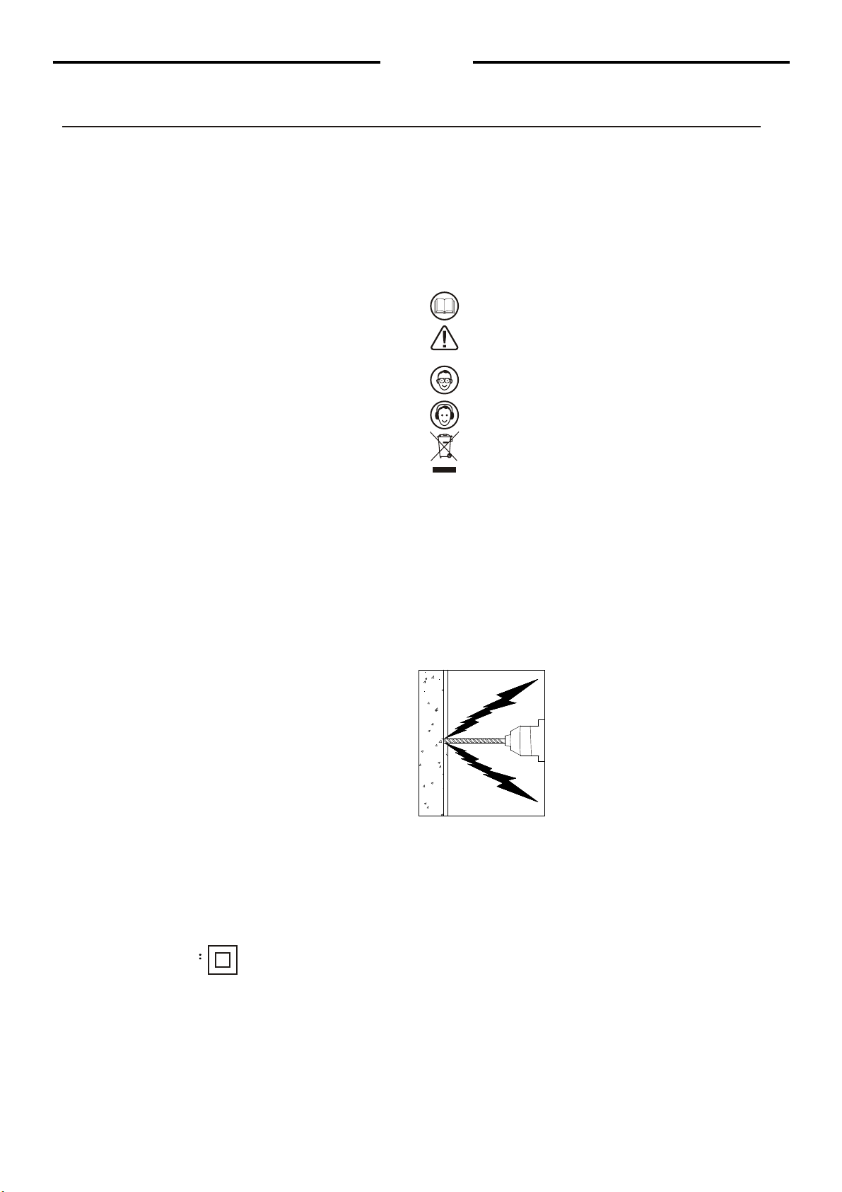
SYMBOLS
Read the manual
Warning
Wear eye protection
Wear ear protection
WEEE marking
5|English
98
7
234
1
10
5
6
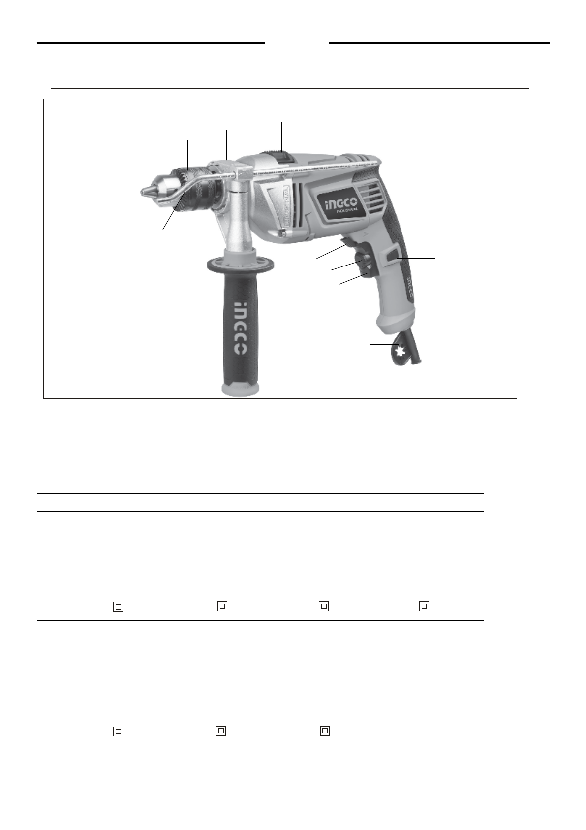
Components, Specifications and Accessories
1 Depth gauge
2 Chuck
3 Locking screw for depth gauge
4 Drill/Impact action selector switch
5 Switch lock button
Components list
Technical Specifications
6 Cable sleeve
7 On/Off switch
8 Variable speed control
9 Forward/reverse selector switch
10 Auxiliary handle
Accessories:
1 Auxiliary handle 1pcs
2 Depth gauge 1pcs
3 BMC 1pcs(only for ID11008-1,UID11008-1)
4 Chuck key 1pcs
Voltage
ID11008Model No.:
Model No.:
Wattage
No-load speed
Chuck capacity
Max drill capacity
Concrete
Wood
Steel
Double insulation
:220-240V ~ 50/60Hz
:1100W
:
:1.5~13mm
:13mm
:25mm
:10mm
0-2800/min
:
ID11008-1(BMC)
220-240V ~ 50/60Hz
1100W
1.5~13mm
0-2800/min
13mm
25mm
10mm
UID11008
110-120V ~ 60Hz
1100W
1/1Ý~1/2Ý
0-2800/min
1/2Ý
1Ý
3/8Ý
Voltage
ID11008-6(ISRAEL plug)
Wattage
No-load speed
Chuck capacity
Max drill capacity
Concrete
Wood
Steel
Double insulation
:220-240V ~ 50/60Hz
:1100W
:
:1.5~13mm
:13mm
:25mm
:10mm
0-2800/min
:
ID11008-8(BS plug)
220-240V ~ 50/60Hz
1100W
1.5~13mm
0-2800/min
13mm
25mm
10mm
ID11008S(SAA plug)
220-240V~ 50/60Hz
1100W
1.5~13mm
0-2800/min
13mm
25mm
10mm
UID11008-1(BMC)
110-120V ~ 60Hz
1100W
1/1Ý ~1/2Ý
0-2800/min
1/2Ý
1Ý
3/8Ý

6|English
Dia 1
Dia 2
Dia 3
Dia 5
Dia 4
Operation
Warning: Before using your drill be sure to read the instruction
manual carefully.
Installing the auxiliary handle (see Dia 1)
For your personal safety we recommend using the
auxiliary handle a t all times.
T o fit the handle, loosen the locking screw for
handle collar anti-clockwise. Slide clamping loop
over the handle collar. Rotate the handle around
the handle collar until the handle is in the desired
position. Tighten the locking screw clockwise to
secure the handle. If you are right handed fit the
handle as shown in Dia2. I f you are left handed fit
the handle the other way round.
Installing the depth gauge (see Dia 2)
The depth gauge can be used to set a constant
depth to drill. To use the depth gauge, loosen the
locking screw for gauge by rotating the auxiliary
handle anti-clockwise. Insert the depth gauge
through hole i n handle. Slide the depth
gauge to required depth and tighten the locking
screw by rotating the locking screw clockwise.
Inserting the key into chuck (see Dia3)
Warning: Before installing tool,
remove mains plug from mains supply.
Remove chuck key from key storage tab at base
of drill handle, place key into chuck, turn key
anti-clockwise to undo/loosen chuck, inset
drill/tool and firmly tighten chuck by turning
key clockwise. Remove key and replace in storage
tab at base of drill handle.
Operating the On/Off switch (see Dia4)
Press the on/off switch i n for operation, release
switch to stop.If you wish t o use the drill
continuously the switch lock button can be
pushed in after the on/off switch has been
depressed. To release the lock button simply
depress on/off switch fully, the button will
automatically release.
Variable speed control selector (see Dia5)
The maximum speed can be altered by turning
the variable speed control. Turn clockwise to
increase and anti-clockwise to decrease speed.
The speed o f the drill varies with the amount of
pressure applied t o the on/off switch, i.e. more
pressure for higher speed.
Locking scre
Auxialiary handle
Turn chuck
key clockwise
to tighten
7|English
Dia
Dia
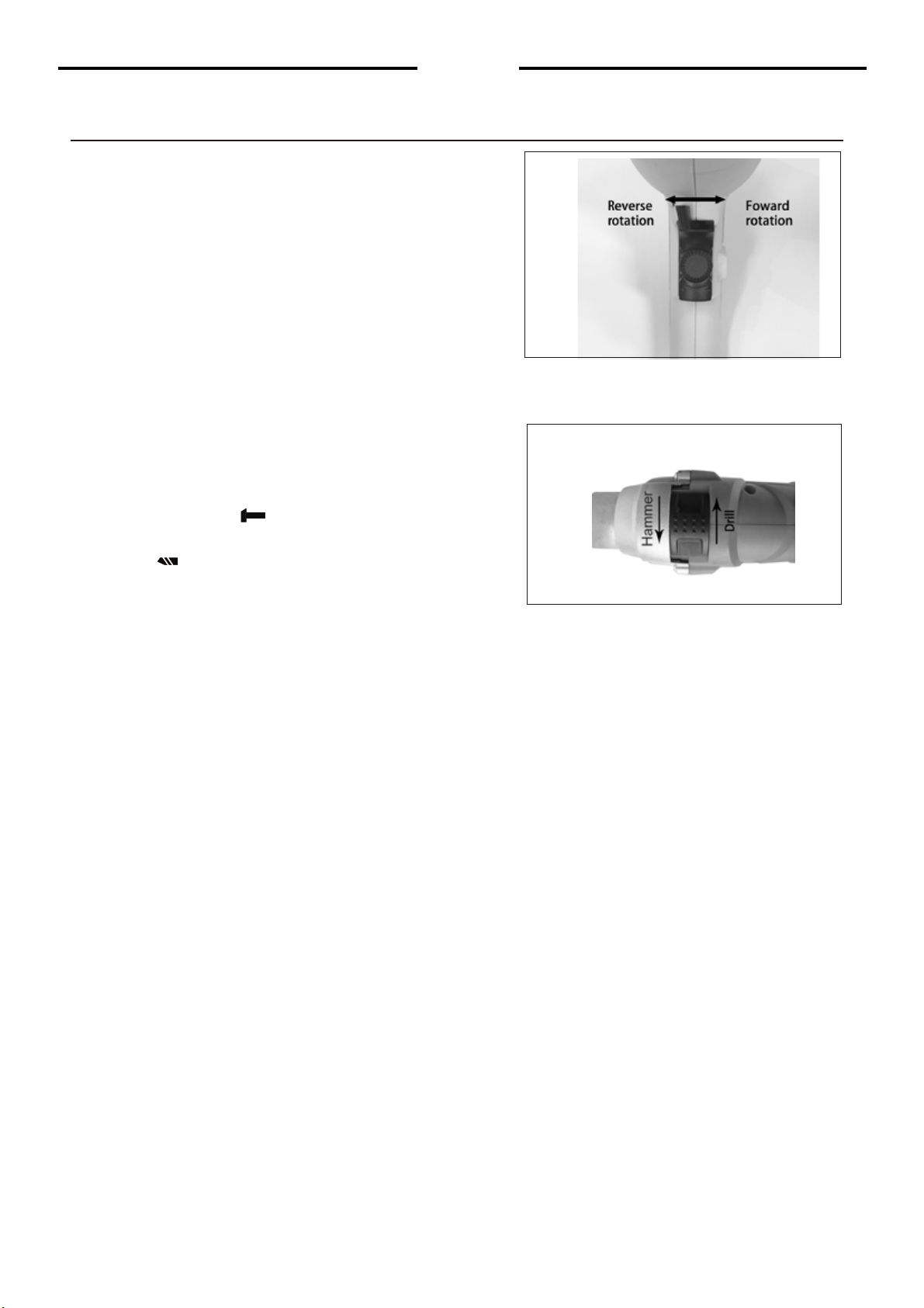
Changing rotational direction (see Dia)
To change the rotational direction, push the
forward/reverse selector switch to the "R"
position indicated on your drill. The rotation
will now b e forward rotation. Push the
forward/reverse selector switch to "L" position
indicated on your drill. The rotation will be
reverse rotation.
Note: Never move the forward/reverse
switch whilst the drill in operation or the
on/off switch is locked as this will damage
the drill.
Drill/Impact action switch (see Dia)
When drilling masonry and concrete push
the drill/impact action selector switch into the
hammer position " ". When drilling wood,
metal, plastic push the switch into the drill
position " ".
Operation

8|English
Maintenance and Troubleshooting
Working hints for your drill
1 Drilling masonry and concrete
Select the drill/impact action selector switch to the "hammer symbol" position.
Tungsten carbide drill bits should always be used for drilling masonry,
concrete etc with a high speed.
2 Drilling steel
Select the drill/impact action selector switch to the "drill symbol" position. HSS
drill bits should always be used for drilling steel with a lower speed.
3 Screw driving
Select the drill/impact action selector switch to the "drill symbol" position.
Use a low speed to drive in or remove screws.
4 Pilot holes
When drilling a large hole in tough material (i.e. steel), we recommend drilling
a small pilot hole first before using a large drill bit.
5 Drilling tiles
Select the drill/impact action selector switch to the "drill symbol" position t o
drill the tile. When tile has been penetrated, switch over to "hammer symbol"
position.
6 Cool the motor
If your power tool becomes too hot, set the speed to maximum and run no load
for 2-3 minutes to cool the motor.
Maintenance
1 Your power tool requires no additional lubrication or maintenance. There are
no user serviceable parts in your power tool.
2 Never use water or chemical cleaners to clean your power tool. Wipe clean
with a dry cloth.
3 Always store your power tool in a dry place.
4 Keep the motor ventilation slots clean.
5 If you see some sparks flashing in the ventilation slots, this is normal and will
not damage your power tool.
6 If the supply cord is damaged, i t must be replaced b y a special cord or
assembly available from the manufacturer o r its service agent.
Troubleshooting
1 If your drill will not operate, check the power at the mains plug.
2 If the drill is not cutting properly, check the drill bit for sharpness, replace
drill bit if worn. Check that the drill is set to forward rotation for normal use.
3 If a fault can not be rectified return the drill to qualified repair personel for service.

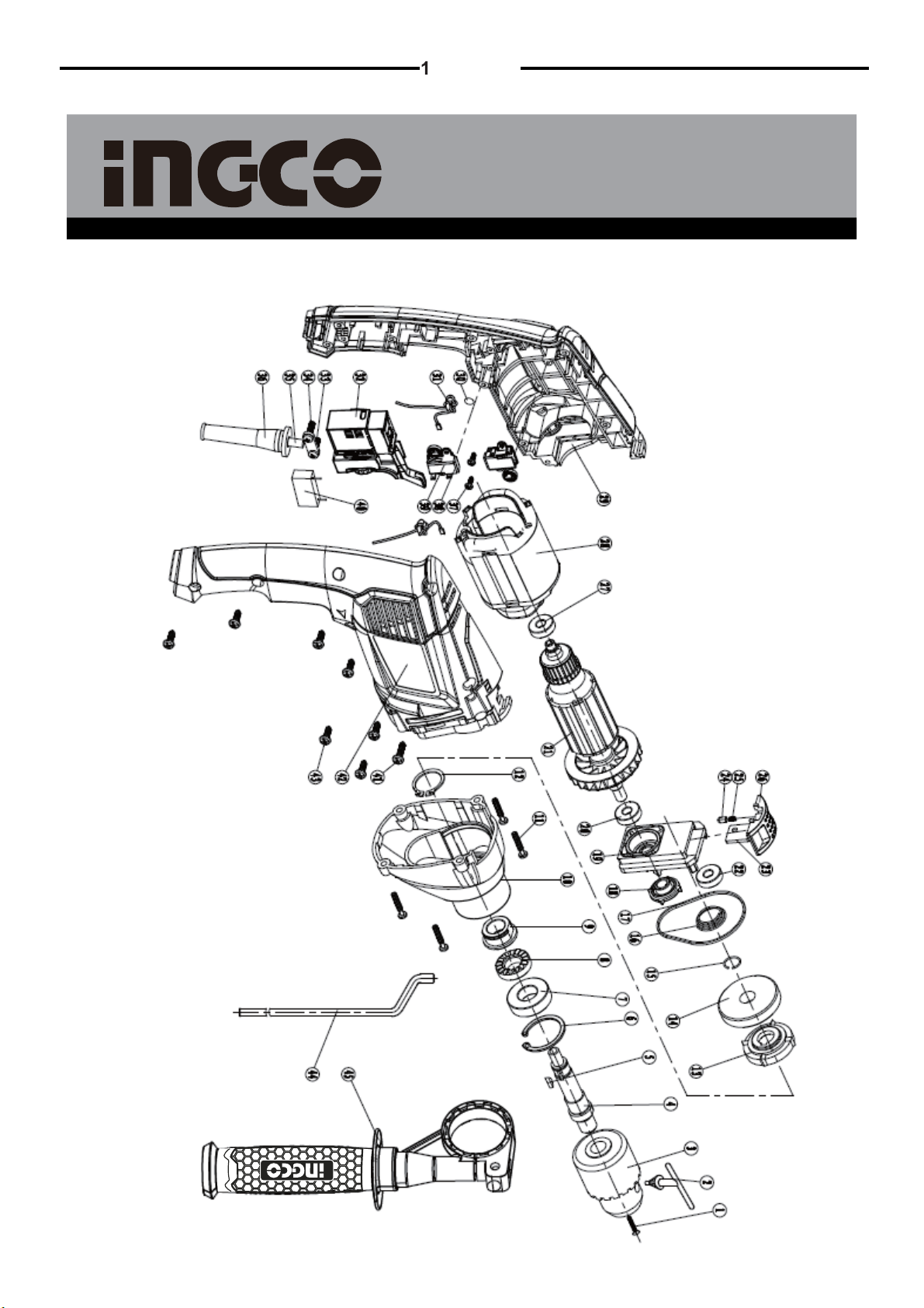
SPARE PART LIST
ID11008,ID11008-1,UID11008,UID11008-1,ID11008S,ID11008-6,ID11008-8 Spare part list
9|English
NO. Part Description
1
2
3
4
5
6
7
8
9
10
11
12
13
14
15
16
17
18
19
20
21
22
23
24
25
26
27
28
29
30
31
32
33
34
35
36
37
38
39
40
41
42
43
44
45
Qty
Screw M6*25
Chunck key
Chuck
Output spindle
3*10Key
Circlip 32
Ball Bearing6002/C3-2RZ
Movable Lapact block
Whisht Lapact Block
Gear Box
ScrewST4*20
Circlip22
Oil Shield
Gear
Circlip12
Spring
Seal Ring
Oil Shield
Support
Ball Bearing608/C3-2RZ
Rotor
Ball Bearing607/C3-2RZ
Slip Plate Drill/Impact Selector
Spring Cap
Spring
Drill/Impact Selector
Bearing607/C3-2RZ
Stator
Left Housing
O Ring
Inductance
Switch
Cord Clamp
Screw
Cord And Plug
Cord Protector
Screw
Carbon Brush
Brush Holder
Capacitor
Screw
Right Housing
Screw
Depth gauge
Auxiliary Handle
1
1
1
1
1
1
1
1
1
1
4
1
1
1
1
1
1
1
1
1
1
1
1
1
1
1
1
1
1
1
2
1
1
2
1
1
4
2
2
1
1
1
7
1
1
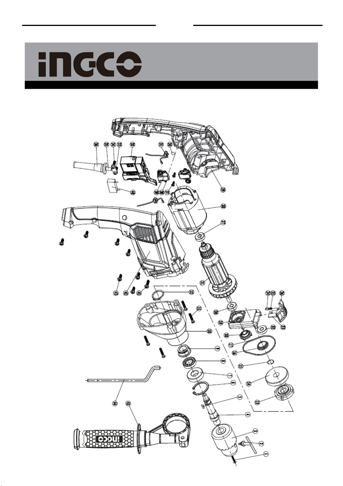
EXPLODING VIEW
10|English
ID11008,ID11008-1,UID11008,UID11008-1,ID11008S,ID11008-6,ID11008-8 Exploding View

INSTRUCCIONES DE SEGURIDAD
¡ADVERTENCIA! Lea todas las instrucciones. El incumplimiento de las
instrucciones que se indican a continuación puede provocar una descarga
eléctrica, incendio y / o lesiones graves. El término "herramienta eléctrica" que
figura a continuación en todas las advertencias, se refiere a sus herramientas
alimentadas por la red de alimentación eléctrica (por cable).
1) Área de trabajo
a) Mantenga el área de trabajo limpia y bien iluminada. Las áreas
desordenadas y oscuras pueden provocar accidentes.
b) No utilice herramientas eléctricas en atmósferas explosivas, tales como
en presencia de líquidos inflamables, gases o polvo. Las herramientas
eléctricas producen chispas que pueden encender el polvo o los gases.
c) Mantenga a los niños y personas cercanas alejados mientras opera la
herramienta eléctrica. Las distracciones pueden hacer perder el control de la
herramienta.
2) Seguridad eléctrica.
a) El enchufe de la herramienta eléctrica debe coincidir con la ficha de la
toma de corriente. Nunca modifique el enchufe.
No utilice ningún adaptador de enchufe con las herramientas eléctricas
que tengan conexión a tierra.
Tomas de corriente no modificada y los enchufes correspondientes reducen el
riesgo de descarga eléctrica.
b) Evite el contacto corporal con superficies a masa (a tierra) tales como
tuberías, radiadores, hornillos y refrigeradores. Esto aumentará el riesgo de
descarga eléctrica.
c) No exponga las herramientas eléctricas a la lluvia o a la humedad. Si
entra agua en la herramienta eléctrica, aumenta el riesgo de descarga eléctrica.
d) No maltrate el cable. Nunca utilice el cable para transportar la
herramienta eléctrica de un lugar a otro, jalar o desenchufarla herramienta.
Mantenga el cable alejado del calor, aceite, objetos cortantes o piezas
móviles. Los cables dañados o enredados incrementan el riesgo de sufrir una
descarga eléctrica.
e) A la hora de trabajar con la herramienta eléctrica en exteriores, utilice el
cable de extensión adecuado. Esto reducirá el riesgo de descarga eléctrica.
1|Español

1|Español
3. Seguridad personal.
a. Manténgase en alerta, observe lo que está haciendo y use el sentido
común cuando utilice una herramienta eléctrica. No utilice la herramienta
eléctrica cuando esté cansado o bajo la influencia de drogas, alcohol o
medicación. Un momento de distracción mientras opera herramientas
eléctricas puede ocasionar lesiones personales graves.
b. Utilice equipo de seguridad. Siempre use protección ocular. Los equipos
de seguridad como la máscara para protegerse de polvo, calzado de seguridad
antirresbalante, casco o protección para los oídos utilizados en condiciones
adecuadas, reducirán las lesiones personales.
c. Evite el encendido accidental de la herramienta. Antes de enchufarlas
asegúrese de que el interruptor está en posición apagado. No transporte
herramientas con el dedo en el interruptor ni enchufe herramientas eléctricas
con el interruptor en posición de encendido. Eso puede provocar accidentes.
d. Retire cualquier llave o tuercas de ajuste antes de encender la
herramienta eléctrica. Una llave en una pieza giratoria de la herramienta
eléctrica puede ocasionar lesiones personales.
e. No se extralimite físicamente. Mantenga la postura y equilibrio en todo
momento. De esta manera mantendrá un mejor control de la herramienta
eléctrica en situaciones inesperadas.
f. Utilice ropa adecuada. No use ropa holgada o joyas. Mantenga su
cabello, la ropa y los guantes alejados de las piezas móviles. La ropa
holgada, joyas o el pelo suelto pueden quedar atascados en las piezas móviles.
g. Si se proveen dispositivos para la conexión de extracción y recolección
de polvo, asegúrese de que estén correctamente conectados y sean
adecuadamente utilizados. El uso de estos dispositivos puede reducir los
riesgos relacionados con el polvo.
4. Mantenimiento y uso de las herramientas eléctricas.
a. No fuerce la herramienta eléctrica. Utilice la herramienta correcta para
su aplicación. La herramienta eléctrica adecuada hará el trabajo mejor y
asegura el rendimiento para el cual fue diseñada.
b. No utilice la herramienta eléctrica si el interruptor no la enciende y no la
apaga. La herramienta eléctrica que no se pueda controlar con el interruptor es
peligrosa y debe ser reparada.
c. Desconecte el enchufe de la fuente de la energía eléctrica antes de
realizar cualquier ajuste, cambiar accesorios, o guardar la herramienta
eléctrica. Dichas medidas de seguridad preventiva reducen el riesgo de
encendido accidental de la herramienta eléctrica.
d. Guarde las herramientas fuera del alcance de los niños y no permita
que personas no familiarizadas con la herramienta eléctrica o con estas
instrucciones operen la herramienta eléctrica. Las herramientas eléctricas
son peligrosas en manos de usuarios que no sean previamente entrenados.
e. Realice el mantenimiento de las herramientas eléctricas. Verifique la
alineación de la unión de las partes movibles, las piezas giratorias y
cualquier otra condición que pueda afectar la operación de las
herramientas eléctricas. Si está dañada, haga reparar la herramienta antes
de usarla nuevamente.
Numerosos accidentes son causados por herramientas mal mantenidas

1|Español
f. Mantenga las herramientas de cortes limpias y afiladas. Las herramientas
con bordes de corte afilados en buen estado de conservación son menos
propensas a trabarse y son más fáciles de controlar.
g. Utilice las herramientas eléctricas, accesorios , brocas, etc. de acuerdo
con estas instrucciones y en la forma prevista para cada tipo particular de
uso de herramienta, tomando en cuenta las condiciones laborales y el
trabajo que se llevará a cabo. El uso de la herramienta eléctrica para
operaciones diferentes a las destinadas podría ocasionar una situación de
riesgo.
5. Servicio técnico
a. Provee el servicio a su herramienta eléctrica por un experto calificado
que utilice sólo las piezas de repuesto idénticas. Esto asegura que se
mantenga la seguridad de la herramienta eléctrica.
Normas de seguridad adicionales para su trabajo con el taladro.
1. Utilice siempre protectores de oídos con el taladro de impacto. La exposición
al ruido puede causar pérdida de la audición.
2. A la hora de utilizar el taladro de impacto, siempre use protectores oculares.
3. Utilice siempre los mangos auxiliares suministrados con la herramienta. La
pérdida de control puede provocar lesiones personales.
4. Siempre revise las paredes y el techo para evitar que los cables de
alimentación tengan contacto con tuberías o cables ocultos. Para este
propósito se puede obtener un detector de metales en cualquier buena
ferretería.
5. No inicie el uso del taladro con la llave de porta brocas en la porta broca.
6. Asegúrese de que el interruptor de encendido no este en la posición "on"
(encendido) antes de ser conectado. Mantenga la herramienta en marcha
solamente cuando esté en sus manos. El taladro se debe siempre desconectar
antes de poner la herramienta en reposo.
7. Sujete el taladro de impacto firmemente con ambas manos.
8. Asegúrese que la broca esté firmemente apretada en la porta broca.
9. No utilice brocas deterioradas o desgastadas.
10. Para sujetar la pieza de trabajo utilice, si es posible, abrazaderas o un torno.
╔╗
El doble aislamiento: ╚╝
La herramienta tiene doble aislamiento. Esto significa que todas las partes
metálicas externas están aisladas eléctricamente de la fuente de alimentación
principal. Esto se logra mediante la colocación de barreras de aislamiento entre
los componentes eléctricos y mecánicos. De esta manera la conexión a tierra
no es necesaria

14|Español
Nota importante
Asegúrese de que su voltaje de alimentación de red es el mismo que el voltaje
en la placa de la herramienta. Antes de realizar cualquier ajuste o reparación,
desenchufe el aparato de la toma.
SÍMBOLOS
fig. Lea el manual
fig. Advertencia
fig. Use protección ocular
fig. Use protección auditiva
fig.Residuos marcados
Componentes, especificaciones y accesorios
Figure
Lista de componentes
1 Tope de profundidad
2 Porta broca
3 Tornillo de fijación de tope de profundidad
4 Interruptor de impacto para seleccionar acción
5 Botón de bloqueo
6 Manga del cable
7 Botón de encendido / apagado (on/off)
8 Control de velocidad variable
9 Botón/ selector de avance y retroceso
10 Mango auxiliar
Especificaciones técnicas
Voltaje:
Potencia:
Velocidad en vacío:
Diámetro de porta broca:
Máximo tope de profundidad Concreto:
Máximo tope de profundidad Madera:
Máximo tope de profundidad Acero:
El doble aislamiento:
ID11008
220-240V~ 50/60Hz
1100W
1.5 ~13mm
13mm
25mm
10mm
0-2800/min
ID11008-1(BMC)
220-240V~ 50/60Hz
1100W
1.5~13mm
13mm
25mm
10mm
0-2800/min
Voltaje:
Potencia:
Velocidad en vacío:
Diámetro de porta broca:
Máximo tope de profundidad Concreto:
Máximo tope de profundidad Madera:
Máximo tope de profundidad Acero:
ID11008S
220-240V~ 50/60Hz
1100W
1.5~13mm
13mm
25mm
10mm
0-2800/min
ID11008-6
220-240V~ 50/60Hz
1100W
1.5~13mm
13mm
25mm
10mm
0-2800/min
ID11008-8
220-240V~ 50/60Hz
1100W
1.5~13mm
13mm
25mm
10mm
0-2800/min
UID11008
110-120V~ 60Hz
1100W
1/16Ý~1/2Ý
1/2Ý
1Ý
3/8Ý
0-2800/min
UID11008-1(BMC)
110-120V~ 60Hz
1100W
1/16Ý~1/2Ý
1/2Ý
1Ý
3/8Ý
0-2800/min

15|Español
Accesorios
1 Mango auxiliar 1 pieza
2 Medidor de profundidad 1 unidad
3 BMC 1pieza
(sólo para taladro de impacto ID11008-1,UID11008-1)
4 Llave de mandril 1 pieza
Operación
_______________________________________________________________
¡Advertencia!
Antes de utilizar el taladro asegúrese de leer con cuidado el manual de
instrucciones.
Instalación del mango auxiliar (ver D1) fig. DIA1
Para garantizar su propia seguridad, le recomendamos utilizar siempre el
mango auxiliar.
Para colocar el mango, afloje el tornillo de fijación del cuello de mango hacia la
izquierda. Deslice la lazada de sujeción sobre el cuello del mango. Gire el
mango alrededor del cuello del mango hasta que el mango esté en la posición
deseada. Ajuste bien el tornillo de bloqueo hacia la derecha para sujetar el
mango. Si usted es diestro, coloque el mango como se muestra en DIA2. Si
usted es zurdo ajuste el mango a la inversa.
Instalación del tope de profundidad (ver DIA2) fig. DIA2
El tope de profundidad se puede utilizar para establecer una profundidad
constante para perforar. Para utilizar el tope de profundidad, afloje el tornillo de
bloqueo de profundidad girando el mango auxiliar en sentido contrario del reloj.
Inserte el tope de profundidad a través del agujero en el mango. Deslice el tope
de profundidad a la profundidad requerida y apriete el tornillo de bloqueo hacia
la derecha (en sentido de reloj.)
Insertar la llave en la porta broca (ver Dia3) fig. Dia3
¡Advertencia!
Antes de instalar la broca/herramienta, retire el enchufe de alimentación
de la red eléctrica.
Retire la llave de la porta brocas que se encuentra en una ficha de llaves en la
base del mango, coloque la llave en la porta brocas, gire la llave hacia la
izquierda para sacar/aflojar la porta broca, inserte la broca / herramienta y
apriete firmemente la porta broca girando la llave hacia la derecha. Retire la
llave y vuelva a colocar la en la ficha, en la base del mango.
Funcionamiento del interruptor ON / OFF (ver Dia4) fig. Dia4
Para poner en marcha la herramienta pulse el botón de encendido / apagado
(on/off) y suelte el interruptor para apagar. Para una operación continua,

1_Español
oprima el interruptor on/off y después empuje el botón de bloqueo. Para soltar
el botón de bloqueo, simplemente presione encendido / apagado por completo,
el botón se soltará automáticamente.
Control de velocidad variable de selección (ver Dia5) fig. Dia5
La velocidad máxima puede ser alterada utilizando el control de velocidad
variable. Para aumentar la velocidad, gire la palanca a la derecha y para
disminuir, hacia la izquierda. La velocidad del taladro varía con la presión
aplicada al interruptor on / off, es decir, si la presión es mayor, aumentará la
velocidad.
Cambio de dirección de rotación (ver Dia)
Para cambiar la dirección de rotación, presione y mueva el selector de
inversión de giro hacia adelante / atrás a la posición "R" que figura en su
taladro. La rotación será ahora hacia adelante. Presione y mueva el selector de
inversión de giro hacia adelante / atrás a la posición "L" que figura en su taladro.
La rotación será ahora inversa.
Nota: Nunca mueva el selector de avance / retroceso, mientras el taladro este
en operación o el interruptor on / off esté bloqueado, ya que podría dañar el
taladro.
Selector de accionamiento (ver Dia)
A la hora de perforar mampostería y hormigón pulse y gire el selector de
accionamiento en la posición de martillo "martillo". Al taladrar madera, metal,
plástico, gire el selector a la posición de perforación "taladro".
Mantenimiento y solución de problemas
Sugerencias para trabajo con el taladro
1) Perforación de mampostería y hormigón
Gire el selector de accionamiento en la posición "símbolo de percusión".
Para perforaciones de mampostería y hormigón deben utilizarse siempre
brocas de carburo de tungsteno, que son para alta velocidad.
2) Perforación de acero
Gire el selector de accionamiento en la posición "símbolo de perforación".
Para perforaciones de acero deben utilizarse siempre brocas HSS, que son
para velocidad menor.
3) Para atornillar
Gire el selector de accionamiento en la posición "símbolo de perforación".
Utilice una velocidad baja para introducir o quitar tornillos.
4) Agujero piloto
Cuando se perfora un agujero grande en material resistente (por ejemplo,
acero), se recomienda primero la perforación de un agujero piloto a pequeña
escala antes de usar una broca grande.
5) Perforación de azulejos
Para perforar el azulejo gire el selector de accionamiento en la posición

1|Español
"símbolo de perforación". Cuando la pieza ha sido perforada, cambie a la
posición " símbolo de martillo ".
6) Enfriar el motor
Si su herramienta eléctrica se calienta demasiado, ajuste la velocidad al
máximo y acciónela sin carga durante 2-3 minutos para enfriar el motor.
Mantenimiento
1. Su herramienta no requiere lubricación ni mantenimiento adicional. No hay
piezas reparables por el usuario en su herramienta.
2. No utilice nunca agua o productos químicos para limpiar su herramienta.
Limpie con un paño seco.
3. Siempre guarde su herramienta en un lugar seco.
4. Mantenga las ranuras de ventilación del motor limpias.
5. Si ve chispas que destellan bajo las ranuras de ventilación, esto es normal y
no dañará su herramienta eléctrica.
6. Si el cable de alimentación está dañado, debe ser sustituido por un cable o
un conjunto especial disponible del fabricante o su agente de servicio.
Solución de problemas
1. Si su taladro de impacto no funciona, revise la alimentación de la red en el
enchufe.
2. Si el taladro no está cortando correctamente, compruebe la nitidez de la
broca, si está desgastada reemplácela. Compruebe que el taladro esté en la
posición de rotación adelante, para el uso normal.
3. Si una falla no puede ser rectificada, entregue el taladro a personal calificado
para su servicio.

ID11008,ID11008-1,UID11008,UID11008-1,ID11008S,ID11008-6,ID11008-8 Lista de piezas
18|Español
NO. Part Description
1
2
3
4
5
6
7
8
9
10
11
12
13
14
15
16
17
18
19
20
21
22
23
24
25
26
27
28
29
30
31
32
33
34
35
36
37
38
39
40
41
42
43
44
45
Qty
Screw M6*25
Chunck key
Chuck
Output spindle
3*10Key
Circlip 32
Ball Bearing6002/C3-2RZ
Movable Lapact block
Whisht Lapact Block
Gear Box
ScrewST4*20
Circlip22
Oil Shield
Gear
Circlip12
Spring
Seal Ring
Oil Shield
Support
Ball Bearing608/C3-2RZ
Rotor
Ball Bearing607/C3-2RZ
Slip Plate Drill/Impact Selector
Spring Cap
Spring
Drill/Impact Selector
Bearing607/C3-2RZ
Stator
Left Housing
O Ring
Inductance
Switch
Cord Clamp
Screw
Cord And Plug
Cord Protector
Screw
Carbon Brush
Brush Holder
Capacitor
Screw
Right Housing
Screw
Depth gauge
Auxiliary Handle
1
1
1
1
1
1
1
1
1
1
4
1
1
1
1
1
1
1
1
1
1
1
1
1
1
1
1
1
1
1
2
1
1
2
1
1
4
2
2
1
1
1
7
1
1
LISTA DE PIEZAS
ID11008,ID11008-1,UID11008,UID11008-1,ID11008S,ID11008-6,ID11008-8 Vista detallada
9|Español
VISTA DETALLADA

20
ID11008,ID11008-1,
UID11008,UID11008-1,
ID11008S,ID11008-6,ID11008-8
This manual suits for next models
6
Table of contents
Languages:
Other Ingco Drill manuals

Popular Drill manuals by other brands

Panasonic
Panasonic EY7411 - CORDLESS DRILL & DRIVER Service manual

Black & Decker
Black & Decker Fire Storm 5146608-00 instruction manual

Milwaukee
Milwaukee 0511-21 manual

Alpha tools
Alpha tools BH 826 operating instructions

Hilti
Hilti DD 30-W Original operating instructions

Hitachi
Hitachi DV 12DV Handling instructions


