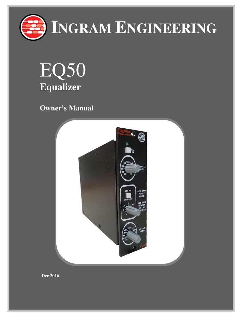
Ingram Engineering EQ52 User manual

INGRAM ENGINEERING
EQ52
Equalizer
Owner’s Manual
May 2021

EQ52 Owner’s Manual
5/2021
2

EQ52 Owner’s Manual
5/2021
3
Table of Contents
INTRODUCTION 5
FRONT PANEL FEATURES 6
EDGE CONNECTOR PIN ASSIGNMENTS 7
SAFETY INSTRUCTIONS 8
INSTRUCTIONS FOR USE 10
1. Installing the EQ52 in a Rack 10
2. Module Warm Up 10
3. EQ In (Bypass Switch) 10
4. Setting Audio Levels 10
5. Low Cut Filter 10
6. See-Saw Filter 11
7. High Cut Filter 13
8. Using Filters in Combination 15
ELECTRICAL SPECIFICATIONS 19
ENVIRONMENTAL SPECIFICATIONS 19
CARE AND MAINTENANCE 20
TROUBLESHOOTING 20
1. Power does not turn on 20
2. Audio Sounds Distorted 20
3. Hum or Buzz is Audible 20
CONTACT INFORMATION 21
WARRANTY INFORMATION 21
EQ52 EQUALIZER RECALL SHEET 24

EQ52 Owner’s Manual
5/2021
4
Table of Figures
Figure 1: Front Panel Features 6
Figure 2: Edge Connector Pin Assignments 7
Figure 3: Low Cut Filter Example Responses 11
Figure 4: See-Saw Filter Example Responses, 1 kHz Pivot Frequency 12
Figure 5: See-Saw Filter Example Responses, Range 1 Pivot Frequencies 12
Figure 6: See-Saw Filter Example Responses, Range 2 Pivot Frequencies 13
Figure 7: High Cut Filter Example Responses 14
Figure 8: Filter Plot, Settings for Smoothing a Stereo Mix 15
Figure 9: Filter Plot with Subtle High Frequency Presence Boost 15
Figure 10: Filter Plot with Settings That Mute Guitar Pick Noise 16
Figure 11: Filter Plot with Settings that Clean Up Muddy Guitar Tracks 16
Figure 12: Filter Plot for Compressor Sidechain Filter, Mid-High Trigger Frequency 17
Figure 13: Filter Plot for Compressor Sidechain Filter, Mid-Low Trigger Frequency 17
Figure 14: Filter Plot with Presence Boost Settings 18
Figure 15: Filter Plot with High Frequency Shelf 18

EQ52 Owner’s Manual
5/2021
5
INTRODUCTION
Welcome, and congratulations on your interest in the EQ52 Equalizer! It has been crafted to
provide extremely high quality audio and a simple user interface that requires minimal effort to
optimize.
The EQ52 contains extremely versatile and musical sounding high pass, low pass and see-
saw filters with a simple and intuitive user interface. Expert circuit design and top quality
components realize an outstanding equalizer that is ideal for individual tracks or for mixing and
mastering stereo signals when the modules are used in pairs.
The unit features differential input and output. Both input and output can operate in differential
or single-ended, unbalanced modes. A high current active output buffer mimics the behavior
of a transformer, providing constant gain for balanced or unbalanced operation, when either
the positive or negative output signals are grounded. Therefore, the output can drive
differential or single ended output with no extra user configuration needed.
The simple controls and circuit layout belie the finely tuned and expertly engineered design.
Extremely high input common mode rejection capability is realized, even down to critical power
supply frequencies. High qualify film caps, low distortion resistors and excellent quality
integrated active stages realize a high headroom, low noise, and low distortion equalizer with
superb audio quality that is ideal for individual tracks or for mixing and mastering stereo
signals.
.

EQ52 Owner’s Manual
5/2021
6
FRONT PANEL FEATURES
Figure 1: Front Panel Features
Pivot Frequency
Sweepable Between 120
Hz and 26 kHz in Two
Ranges
See-Saw Filter
Simultaneously Adjusts
High / Low Frequencies
High Cut Filter
Sweepable from 3 kHz to
>200 kHz
Low Cut Filter
Sweepable from 50 Hz to
5 kHz in Two Ranges
Hardwire Bypass Around
the Entire EQ
Adjusting the Knob
Clockwise Boosts Highs /
Cuts Lows
Counter-Clockwise
Boosts Lows / Cuts
Highs

EQ52 Owner’s Manual
5/2021
7
EDGE CONNECTOR PIN ASSIGNMENTS
Power, ground and audio signal interface to the EQ52 is through the edge card connector at
the rear of the module. Assignments of the edge card connector pins follow:
Pin 1
Chassis Ground
Pin 2
Output, Balanced, Positive
Pin 3
No Connection
Pin 4
Output, Balanced, Negative
Pin 5
Audio Ground
Pin 6
No Connection
Pin 7
No Connection
Pin 8
Input, Balanced, Negative
Pin 9
No Connection
Pin 10
Input, Balanced, Positive
Pin 11
No Connection
Pin 12
+16V DC
Pin 13
Power Ground
Pin 14
-16V DC
Pin 15
No Connection
Figure 2: Edge Connector Pin Assignments

EQ52 Owner’s Manual
5/2021
8
SAFETY INSTRUCTIONS
1. Read Instructions
All the safety and operation instructions should be read before this product is operated.
2. Retain Instructions
The safety and operating instructions should be kept for future reference.
3. Heed Warnings
All warnings on the product and in these operating instructions should be followed.
4. Follow Instructions
All operating and other instructions should be followed.
5. Water and Moisture
This product should not be used near water or in environments with very high humidity
or with condensation.
6. Heat
This product should be situated away from heat sources such as radiators or other
devices that product heat.
7. Power Sources
This product should be connected to a power supply only of the type described in these
operation instructions or as marked on this product.
8. Object and Liquid Entry
Care should be taken so that objects do not fall into and liquids are not spilled into the
inside of this product.
9. Damage Requiring Service
This product should be serviced only by qualified service personnel when:
a. Objects have fallen, or liquid has spilled into the product; or
b. The product has been exposed to rain; or
c. The product does not appear to operate normally or exhibits a marked change in
performance; or
d. The product has been dropped, or its chassis damaged.

EQ52 Owner’s Manual
5/2021
9
10.Servicing
The user should not attempt to service this product beyond those means described in
this operating manual. All other servicing should be referred to the Ingram Engineering
Service Department.
Warning –To reduce the risk of fire or electric shock, do not expose this appliance to
rain or moisture.

EQ52 Owner’s Manual
5/2021
10
INSTRUCTIONS FOR USE
1. Installing the EQ52 in a Rack
RACK POWER MUST BE OFF BEFORE INSTALLING THE EQ52. The module
design is not warrantied for damage that occurs when it is inserted or removed from a
rack with power applied.
2. Module Warm Up
After power up, please allow approximately 2 minutes time for component warm up and
stabilization time before beginning critical listening or recording.
3. EQ In (Bypass Switch)
The EQ In button engages the EQ or switches in a hard-wire bypass of the entire EQ
module. With balanced input and most types of equipment used in conjunction with this
EQ, the EQ has unity gain. Therefore, by alternating between EQ In and EQ Out, the
Bypass Switch is an effective tool to audition the effect of the EQ. An LED indicates
when the EQ is engaged.
4. Setting Audio Levels
Ideal levels for the EQ52 are 0 dBu nominal at mid frequencies. While the EQ52 can
accept audio levels up to +20 dBu when the EQ settings are flat, the see-saw filter has
as much as +8 dB gain when adjusted to its extremes, so it is good practice to set the
EQ52 input levels to 0 dBu for maximum headroom. The Low Cut and High Cut filters
only attenuate the signal, so these filters will not be a factor in setting levels.
5. Low Cut Filter
The Low Cut Filter is a passive first order filter that provides gentle -6dB / octave cut to
frequencies below that indicated on the knob. The cutoff frequency adjustment range is
very wide, and extends from 50 Hz to 5 kHz in two ranges. The range is selected by a
push button. By using a low order -6dB/octave filter, smooth and natural filtering of
music is achieved with minimal phase shift. By providing cutoff frequency as high as 5

EQ52 Owner’s Manual
5/2021
11
kHz, significant attenuation of lowest frequencies can be achieved. The plot below filter
responses over both ranges.
Figure 3: Low Cut Filter Example Responses
6. See-Saw Filter
The See-Saw Filter provides simultaneous cut of one frequency band while boosting
another band. When the adjustment knob is turned clockwise, high frequencies are
boosted and low frequencies are cut. When the adjustment knob is turned count-
clockwise, low frequencies are boosted and high frequencies are cut. The filter has
approximately linear slope over the transition region. Max boost and cut are
approximately 8dB, so significant shaping of the audio spectrum can be achieved.
The See-Saw filter has a “pivot” frequency that can be sweep over an extremely wide
range of 120 Hz to 26 kHz, in two ranges. The range is selected using a front panel
push button. The See-Saw filter has the same linear slope for each setting. Plots
below show a range of filter responses.
Low Cut
Range 1
Low Cut
Range 2
Low Cut Off

EQ52 Owner’s Manual
5/2021
12
Figure 4: See-Saw Filter Example Responses, 1 kHz Pivot Frequency
Figure 5: See-Saw Filter Example Responses, Range 1 Pivot Frequencies

EQ52 Owner’s Manual
5/2021
13
Figure 6: See-Saw Filter Example Responses, Range 2 Pivot Frequencies
7. High Cut Filter
The High Cut Filter is a passive first order filter that provides gentle -6dB / octave cut to
frequencies above that indicated on the knob. The cutoff frequency adjustment range is
very wide, and extends from 3 kHz to >200 kHz. By using a low order -6dB/octave filter,
minimal phase shift of the signal is realized and very natural sounding filtering results.
By providing cutoff frequency as low as 3 kHz, significant attenuation of highest
frequencies can be achieved. The plot below shows a range of filter responses.

EQ52 Owner’s Manual
5/2021
14
Figure 7: High Cut Filter Example Responses

EQ52 Owner’s Manual
5/2021
15
8. Using Filters in Combination
The following plots show examples applications of the three filters, used in combination.
Smooth a stereo mix using the Low Cut and See-Saw filters.
Figure 8: Filter Plot, Settings for Smoothing a Stereo Mix
Subtle presence boost using the See-Saw, some band limiting using the High Cut filter.
Figure 9: Filter Plot with Subtle High Frequency Presence Boost

EQ52 Owner’s Manual
5/2021
16
Using combinations of the See-Saw and High Cut filters as shown below can turn bright
guitar tracks played with a pick into tracks that sounds like they were played using only
fingers.
Figure 10: Filter Plot with Settings That Mute Guitar Pick Noise
The filters can also be used to clean a muddy guitar track by using the See-Saw and
Low Cut filters.
Figure 11: Filter Plot with Settings that Clean Up Muddy Guitar Tracks

EQ52 Owner’s Manual
5/2021
17
The EQ52 can be used as a compressor sidechain filter. An example setting shown
below would realize compression that is triggered on mid-highs. This plot uses a
combination of the Low and High Cut filters.
Figure 12: Filter Plot for Compressor Sidechain Filter, Mid-High Trigger Frequency
The sidechain filter example below would realize compression triggered on mid-low
frequencies.
Figure 13: Filter Plot for Compressor Sidechain Filter, Mid-Low Trigger Frequency

EQ52 Owner’s Manual
5/2021
18
Slight low-end boost and high frequency reduction using the See-Saw and High Cut
filters.
Figure 14: Filter Plot with Presence Boost Settings
High frequency shelving using the See-Saw filter.
Figure 15: Filter Plot with High Frequency Shelf

EQ52 Owner’s Manual
5/2021
19
ELECTRICAL SPECIFICATIONS
(TA=+25°C unless otherwise noted)
Parameter
Min
Typ
Max
Unit
Comments
Input Impedance
48
k Ω
Differential
Output Impedance
100
Ω
Differential
Gain
0
dBr
EQ Engaged, Diff Input
Max Input Level
+20
dBu
With <0.5% THD
Frequency Response
<10
>250k
Hz
±3.0 dB, Equalizer On with Flat
Adjustment
Low Cut Filter
Cutoff Frequency, Range 1
Cutoff Frequency, Range 2
50
700
600
5k
Hz
Stopband Slope
-6
dB/Octave
High Cut Filter
Cutoff Frequency Range
3
>200
kHz
Stopband Slope
-6
dB/Octave
See-Saw Filter
Pivot Frequency, Range 1
Pivot Frequency, Range 2
120
1.9k
1.7k
26k
Hz
Hz
Boost / Cut
-8
+8
dB
With Control Fully CW or CCW
Filter Slope
6
dB/Octave
With Max Boost/Cut
THD + Noise
0.002
%
With +20 dBu Input, 1 kHz
Signal, 22 kHz Bandwidth
Noise
-97
dBu
A-weighting, flat filter response
CMRR
90
dB
At 60 Hz
Voltage Supplies
±16
V
Current
±25
mA
ENVIRONMENTAL SPECIFICATIONS
Parameter
Min
Typ
Max
Unit
Comments
Operating Temperature
0
85
°C
Humidity
30
80
%
Non-condensing

EQ52 Owner’s Manual
5/2021
20
CARE AND MAINTENANCE
1. Cleaning
Avoid solvents or chemicals that may dissolve the silkscreen text on the front and back
panels.
TROUBLESHOOTING
1. Power does not turn on
First verify that power is being applied to the module by engaging the EQ In function. It
has a Green LED that illuminates when the EQ is engaged. If this LED does not come
on, verify that the 500-rack has power applied and is switched on. Check the rack AC
fuse.
2. Audio Sounds Distorted
Check the level being applied to the EQ52. 0dBu (-4VU) is the best nominal audio level
to use with the EQ52. The See-Saw filter can realize 8 dB gain when adjusted to its
extremes. If EQ52 input levels exceed 12 dBu, it is possible that the audio is being
distorted if extreme See-Saw filter settings are being used.
If distortion cannot be attributed to signal levels or filter settings, check the integrity of
the 500-series rack power supply. If these tips do not solve the problem, investigate
other system equipment, then contact Ingram Engineering.
3. Hum or Buzz is Audible
Check the integrity of the system cables. If the 500-Series rack includes a ground lift for
the balanced audio cable, try lifting the ground. Check the integrity of the 500-Series
rack power supply.
Table of contents
Other Ingram Engineering Stereo Equalizer manuals
