INIM Electronics Air2-BS200 Assembly instructions

"JS#4
8JSFMFTT USBOTDFJWFS NPEVMF
E
EN 50131-1
EN 50131-3
EN 50131-5-3
EN 50130-4
EN 50130-5
INCERT
CEB T031
*OTUBMMBUJPO BOE QSPHSBNNJOH NBOVBM

Table of contents
1. Air2 system description 3
2. Description of Air2-BS200 4
2.1 Description of parts 5
2.2 Technical specifications Air2-BS200 6
2.3 Status LED 6
3. Operating principles 7
3.1 Wireless terminals 7
3.2 Wireless keypads and sounders 7
4. Installation of Air2-BS200 8
4.1 Addressing of Air2-BS200 9
4.2 Enrolling a wireless device 10
5. System programming Air2 12
5.1 Programming of Air2-BS200 12
5.2 Transceiver parameters 13
5.3 Programming from Air2-BS200 13
6. General information 15
6.1 About this manual 15
6.2 Manufacturer's details 15
6.3 Notes from the Manufacturer 15
6.4 Simplified EU Declaration of Conformity 15
6.5 Documents for the users 16
6.6 WEEE 16
2Installation and programming manual- 100-DRAFT

Air2-BS200 | © 2020 Inim Electronics S.r.l. 3
1. Air2 system description
All anti-intrusion systems INIM can manage the two-way wireless system Air2 characterized by a MHz carrier
frequency 868 MHz.
The system components Air2 are:
Air2-BS200/50 transceiver module, 50 terminals
Air2-BS200/30 transceiver module, 30 terminals
Air2-BS200/10 transceiver module, 10 terminals
Air2-KF100 4 button remote-control key
Air2-Ergo 4 button remote-control key
Air2-Pebble 4 button remote-control key
Air2-MC200 magnetic contact with shock and tilt sensor in white or brown
Air2-MC300 magnetic contact with two I/O terminals, in white or brown
Air2-FD100 smoke detector
Air2-Aria/W keypad with graphic display
Air2-Hedera outdoor sounder, in white or chrome effect
Air2-Smarty/W indoor sounderflasher
Air2-DT200T dual technology curtain detector, in white or brown
Air2-XIR200W PIR detector, 12 m
Air2-XDT200W dual technology curtain detector
Air2-UT100 universal transceiver
Air2-ODI100W outdoor wireless dual-infrared detector
Air2-OTT100W outdoor wireless triple-technology detector
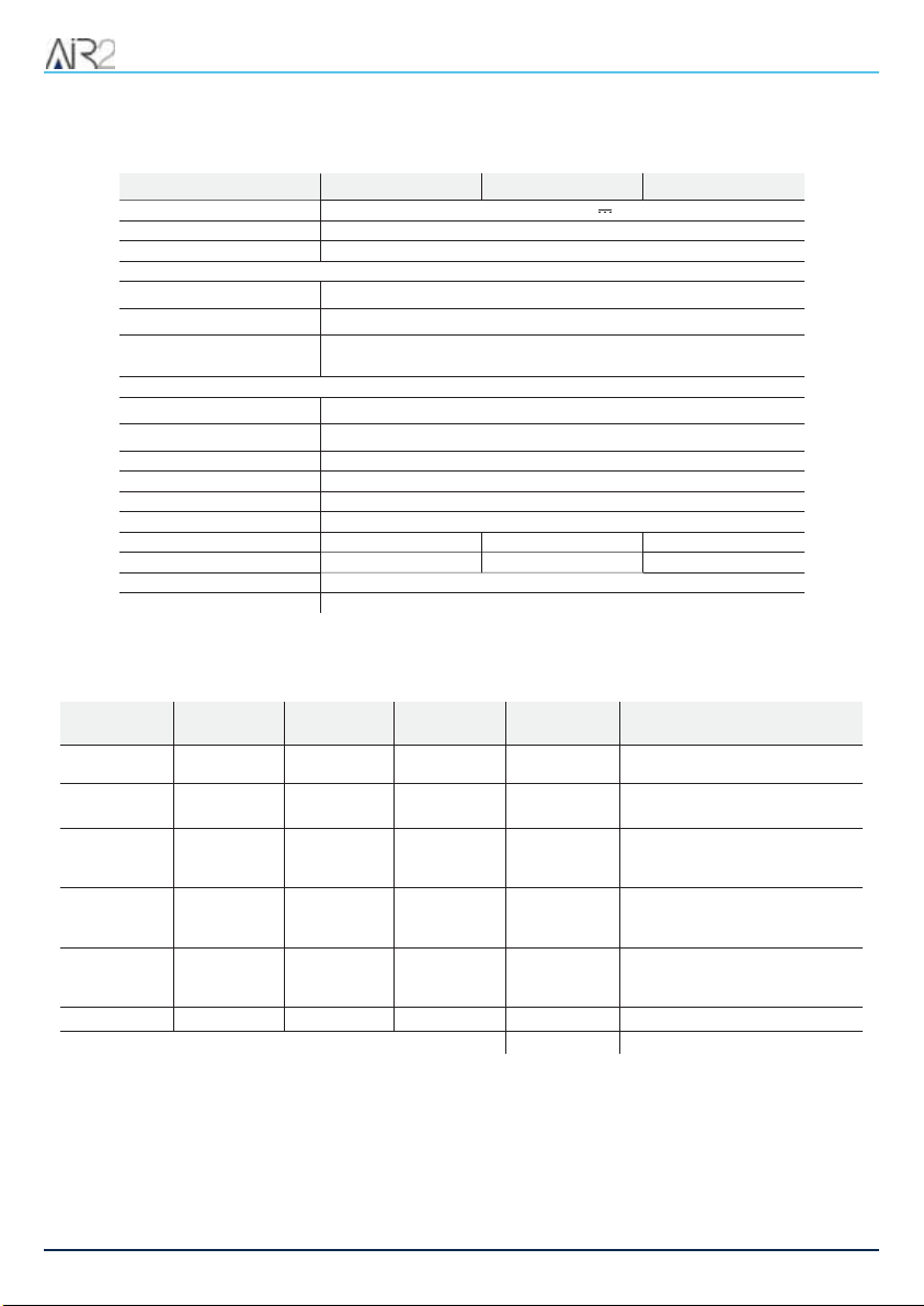
Technical specifications of the system Air2
Operatingfrequency
range 868.0 - 868.6 MHz
selectable channels 868.1, 868.3, 868.5 MHz
RF output power 25mW e.r.p.
Communication type Two-way
Modulation GFSK
Device supervision from 12 to 250 minutes
/PUF
In orderto comply with theEN 50131-1standards thealarm systemsupervisiontime must be below 120minutes.

2. Description of Air2-BS200
2. Description of Air2-BS200
The wireless module Air2-BS200 allows the integration and management of wireless detectors, keypads,
sounders in the hardwired environments of all models of intrusion control panels INIM.
The module simulates:
a reader, at a programmed address (ADD), which allows you to configure the remote control keys
up to 10 expansion boards, at addresses ADD, ADD+1, ... ADD+9, capable of managing the ter-
minals
Additionally, each Air2-BS200 allows the Inim control panel to manage up to 4 wireless keypads and 4 wire-
less sounders.
4Installation and programming manual- 100-DRAFT

Air2-BS200 | © 2020 Inim Electronics S.r.l. 5
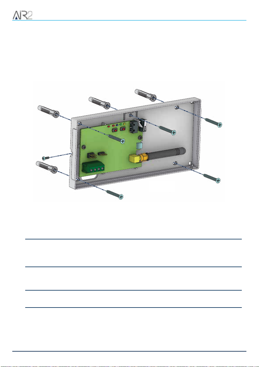
2.1 Description of parts
2.1 Description of parts
<">LJ PCB board
<#>LJ BUS connection terminals
<$>LJ Configuration connectors
<%>LJ USB-micro connector
<&>LJ Tamper microswitch: Open
cover
<'>LJ Tamper microswitch: Dis-
lodgement
<(>LJ Button P1
<)>LJ Button P2
<*>LJ LED DL1 - red
<+>LJ LED DL2 - blue
<,>LJ LED DL3 - green
<->LJ LED DL4 - yellow
<.>LJ PRG LED - red
</>LJ Antenna connector
<0>LJ Backbox
<1>LJ Mounting screw location
<2>LJ Tamper-screw location
<3>LJ Cable entry
<4>LJ Enclosure screw hole
2. Description of Air2-BS200
2.2 Technical specifications Air2-BS200
Model Air2-BS200/10 Air2-BS200/30 Air2-BS200/50
Power Supply Voltage from 9 to 15V
Current draw 30 - 50 mA
Bus type I-BUS / BUS RS485
Antenna
connector SMA female
impedance 50 Ohm
ACE type
(Ancillary Control Equipment) A
Operating environmental conditions
Temperature from -10 to +40 °C
Relative humidity ≤93% without condensation
Security rating 2
Environmentalclass II
Dimensions (W x H x D) 80 x 170 x 25 mm
Weight 135 g
Terminals 50 30 10
Remote controlkeys 100 50 30
Keypads 4
Sounder/flashers 4
2.3 Status LED
LED DL1 red LED DL2 blue LED DL3 green LEDDL4 yel-
low PRG LED red Signal
Off Discontinuous
flashing Off Off Off Wireless data reception
Off Off Discontinuous
flashing Off Off Programming phase in progress
(from 1 to 5, for SmartLiving only)
Off Off Off solid / blinking Off
Parameter/Value undergoing pro-
gramming
(for SmartLiving only)
Off Off Continuous
flashing Off Off
Enrollment of wireless device in pro-
gress
(requested at the control panel)
Off Off Continuous
flashing
Continuous
flashing Off
Erroneous programming
(for example, two devices on the
same terminal)
1 flash 1 flash 1 flash 1 flash Off Reset factory default settings
solid /off / blinking Off Address Programming (phase 6)
6Installation and programming manual- 100-DRAFT

Air2-BS200 | © 2020 Inim Electronics S.r.l. 7
3.1 Wireless terminals
3. Operating principles
In order to configure Air2-BS200 it is necessary to assign an address between 1 and 30 in the control panel
(to set the address follow the instructions in paragraph 4.1 AddressingofAir2-BS200).
The selected address will be assigned to the simulated reader (which processes and manages wireless
transmissions in the same way as keys) and to the first 10 expansion boards, also simulated, with suc-
cessive addresses “ADD”, “ADD”+1, ..., “ADD”+9.
Conditions for secure deployment and operations:
there must be no other transceivers at the selected address
the simulated reader must be enrolled on the control panel
there must be no other readers at the same address (nBy/X or built into the keypad)
the simulated reader need not be associated with any partitions
the simulated expansion boards must be enrolled on the control panel
an expansion board will be considered part of the wireless network only when one of its terminals is
configured as “wireless”
a simulated expansion board cannot share its assigned address with other hardwired FLEX5 expan-
sion boards.
3.1 Wireless terminals
A terminalcan be considered a “Wireless” terminal only underthe following conditions:
it must not be configured as a “Double” zone (D)
if configured as a “Zone”, it must not be configured as “Shock” in the detector type field
it must be assigned to an expansion board (and not to the control panel or keypads)
3.2 Wireless keypads and sounders
The Inim intrusion control panel can manage up to 4 keypads (Air2-Aria/W) and 4 sounders (Air2-Hedera
and Air2-Smarty/W) for eachAir2-BS200. However, each control panel model supports a maximum number
of keypads and sounders which must be respected.
During the addressing phase it is necessary to use only the free addresses and to ensure that no other
keypads (Aria/HG, Joy, Concept, nCode or Alien) are present at the address of the wireless keypads, or
othersounders at the address of the wireless sounders to be configured.
Forthe addressing procedure and the programming of these devices, refer to the respective manuals.
4. Installation of Air2-BS200
4. Installation of Air2-BS200
For optimal performance of the wireless system the transceiver module Air2-BS200 must be located at the
core of the wireless network and area of use of remote-control keys, in a placement which allows easy con-
nection of the I-BUS cable to the control panel.
Allwireless protection devices should be located high up in order to increase their detection capabilities and
prevent inadvertent masking caused by large objects or building occupants.
"UUFOUJPO
Ferromagnetic materials which are located in the vicinity of the mounting position can
influence the magnetic field and can result in the reduced operating capacity of the
device.
It is possible to view on the keypads or via the programming and supervision software, the strength of the
wireless signal on each wireless device Air2-BS200; this data can be used to optimize the installation pro-
cess.
/PUF
A level 3 signal strength it is recommended for agood installation.
As an integral part of the system, the Air2 provides 3 inter-module transmission channels. This feature allows
you to select the channel in such way as to avoid over-the-airinterference between two close-proximity wire-
less systems (for example, in two adjoining apartments).
8Installation and programming manual- 100-DRAFT
Air2-BS200 | © 2020 Inim Electronics S.r.l. 9
4.1 Addressing of Air2-BS200
Forsecure deployment and operations of the wireless intrusion protection system Air2 it is necessary to refer
to the Installation and programming guide of the hardwired intrusion control panel in use.
1. Choose a suitable mounting placement.
2. Using a flat-bladed screwdriver in the enclosure screw location, push open the enclosure and sep-
arate the two parts.
3. Hold the base to the chosen mounting placement and mark the screw holes and tamper protection
position.
4. Pull the wires through the cable entry and wire up the transceiver.
5. Using the screws, secure the base and the tamper protection in position.
6. Enroll the device.
7. Re-attach the cover to the base and replace the enclosure screw.
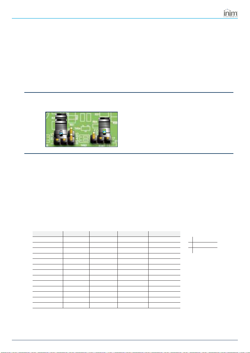
"UUFOUJPO
Do not change the setting of the jumpers on the connectors.
4.1 Addressing of Air2-BS200
During the enrolling phase the wireless transceiver Air2-BS200 is integrated into the intrusion control panel
INIM by simulating:
a reader, with the address programmed via the module itself (ADD), by means of buttons P1 and P2
on the PCB;
up to 10 expansion boards, at addresses ADD, ADD+1, ... ADD+9, to manage the terminals and to
be configured via the software project template
The address must be set during the programming phase of the reader. During this phase the address is indic-
ated by LEDs DL 1-4 in accordance with the following:
Readeraddress LED DL1 - red LED DL2 - blue LED DL3 - green LED DL4 - yellow
100 0 1
0LED Off
200 1 0
1LED On
300 1 1
LFlashing LED
401 0 0
501 0 1
601 1 0
701 1 1
810 0 0
910 0 1
10 10 1 0
11 10 1 1
12 11 0 0
13 11 0 1
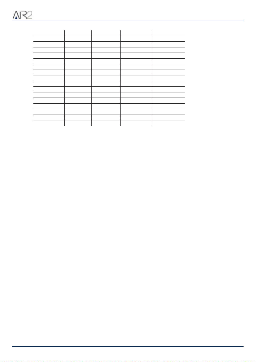
4. Installation of Air2-BS200
14 11 1 0
15 11 1 1
16 00 0 L
17 00 L 0
18 00 L L
19 0L 0 0
20 0L 0 L
21 0L L 0
22 0L L L
23 L0 0 0
24 L0 0 L
25 L0 L 0
26 L0 L L
27 LL 0 0
28 LL 0 L
29 LL L 0
30 LL L L
1. Put the intrusion control panel in maintenance mode.
2. Press button P1 to access the address setting menu. During this phase the PRG LED will switch On
and the LEDs will show the current address.
3. Use the P2 to reach the address to be assigned.
4. Use the P1 button to assign the address and exit the menu (phase 0).
5. Include the wireless expansion boards in the control panel configuration, starting from the “ADD”
address (maximum “ADD” +9).
6. In the control panel configuration set the presence of the reader at the "ADD" address, simulation of
the transceiver associated with the wireless devices.
During normal operating status of Air2-Smarty/W, pressing and holding the P2 button will allow you to view
(but not change)the transceiver address indicated on its LEDs.
4.2 Enrolling a wireless device
The enrolling procedure allows you to associate a wireless device INIM with the transceiver Air2-BS200
which acts in conjunction with the intrusion control panel.
This procedure varies depending on the control panel in use and the programming software orapplication:
1. Access the control panel programming.
2. Select the device to be enrolled in accordance with its type:
an input terminal, for a detector (motion detector, magnetic contact, etc.)
an output terminal, for an output device connected to a terminal of a magnetic contact Air2-
MC300
a keypad
a sounder/flasher
a key, for a remote control device, selecting as the associated reader the one simulated by the
transceiver
3. Set the device as “Wireless”.
10 Installation and programming manual- 100-DRAFT

Air2-BS200 | © 2020 Inim Electronics S.r.l. 11
4.2 Enrolling a wireless device
/PUF
If a terminal on theexpansion boardis configured as “wireless”, all theremainingterminals must beconfiguredas
“wireless” terminals.
4. Start the learning phase from the control panel.
5. If you are enrolling an output device that is connected to an output terminal of Air2-MC300 it is neces-
sary to enable the “Broadcast RF” zone option.
/PUF
The “Broadcast RF” option must be enabledfor each terminal of the device Air2-MC300 concerned.

5. System programming Air2
5. System programming Air2
The programming of a system Air2 concerns the parameters of the transceiver, which simulates a reader dur-
ing the enrolling phase and an expansion board during normal operations and manages the devices rep-
resented by wireless terminals.
Each device Air2 that transmits to the control panel through Air2-BS200 therefore it has operating para-
meters and options, accessible through the programming sections of the control panel terminals.
&YBNQMF
To program an intrusion control panel which requires:
12 hardwired zones of which 3 on the control panel, 2 on a keypad, 7 on 2 expansion boards
18 wireless zones
5 remote-control keys
Minimum requirements: 18/5=4 expansion boards; if the 2 expansion boards are for the hardwired zones
assign them to addresses 1 and 2; set the Air2-BS200 DIP-microswitches to address 3 (LED DL1 Off, DL2
Off, DL3 On, DL4 On).
Enrollexpansion boards 3, 4, 5 and 6 and reader3 on the control panel.
In the “Terminals” programming section, select terminal T1 of expansion board 3 and enroll the detector.
Enroll all the wireless devices consecutively.
In the “Keys-Enroll” programming section, select reader 3 then select the number of remote-control keys you
wish to enroll.
1SPHSBNNJOHUIF DPOUSPM QBOFM
The actual programming process for control panels Inim Electronics offers the following parameters for the
management of the wireless system Air2:
Instant reset of wire-
less magnetic contact If this option is enabled, reset of the magnetic reed sensor of wireless detectors will be signalled
instantly (otherwise signalling has a maximum delay of 10 seconds).
Wireless supervision
time
This parameter allows the selection of the supervision time of wireless devices. On expiration of the
programmed time, any wireless devices which do not respond will be signalled as lost.
Accepted values: 12 to 250 minutes.
5.1 Programming of Air2-BS200
Programming of a transceiver Air2-BS200, with transmission parameter settings for all devices Air2, it is pos-
sible via the programming software Inim Electronicswith Prime system keypads and, if a transceiver is
installed in a SmartLiving system, directly by means of the buttons on the device itself (5.3 Programming
fromAir2-BS200).
Programming softwares Inim Electronicshave a section that allows you to view all the enrolled wireless
devices and set the programming parameters of each individual transceiver Air2-BS200.
The “Wireless transceivers” section is divided in sub-sections, one for each receiver configured. Each sub-
section shows:
12 Installation and programming manual- 100-DRAFT

Air2-BS200 | © 2020 Inim Electronics S.r.l. 13
5.2 Transceiver parameters
the transceiver model
the firmware version of the transceiver board
the transceiver parameters
a list of devices enrolled by the transceiver;
for each device it shows:
the Icon
the terminals (where present)
the serial number
the model
5.2 Transceiver parameters
The programming software, selecting a transceiver, sets the following functions and parameters:
Clone remote-con-
trol keys
This function starts the guided cloning process of the wireless keys enrolled via the transceiver of the selec-
ted reader.
The guide allows you to indicate which transceiver, from those selectable, the cloned keys will be assigned
to.
RF
This function starts an operation which attenuates (6db) the wireless signal transmitted by the transceivers
for 5 approximately minutes.
During this period the installer can carry out tests on the stability of the RF connection under weak-signal
conditions.
Channel
Section for the selection of the wireless communication channel used by the transceiver that simulates the
reader that is undergoing programming:
Channel 001,868.1 MHz
Channel 002,868.3 MHz
Channel 003,868.5 MHz
Disable tamperpro-
tection This option disables the tamper signal of the transceiver.Air2-BS200.
Disable the Rolling
Code
This option disables the use of a rolling-code algorithm for the transmission of wireless commands via the
moduleAir2-BS200.
Deactivation can be useful to the installer when the same wireless command device is used on several sys-
tems.
5.3 Programming from Air2-BS200
Programming from a module Air2-BS200 allows you to set only some of the system programming para-
meters Air2 and only when used with a SmartLiving system.
This programming also includes a specific section for the addressing of the Air2-BS200, available for both
SmartLiving and Prime control panels.
The available programming phases correspond to the 6 different sections in the Programming menu. Use
the buttons and LEDs on the PCB of the module to navigate through the 6 programming phases.
1. Press the P1 button.
The programming menu will open.
2. Press the button again until access to the required phase is achieved. LED DL3 will emit a number of
blinks corresponding to the current phase.
3. Using the P2 button carry out any changes (where required). Where required, LED DL4 will show the
current data.
4. Save any changes and exit the programming session.
This can be done in two ways:

5. System programming Air2
o
Use the P1 button to step back.
o
Press and hold the P2 button for at least 3 seconds. The 5 LEDs will light to confirm that the data
has been saved.
If this procedure is carried out during phase 2, the device will reset to factory default settings.
1IBTF
Stand-by:normal operating phase of the Air2-BS200 and its LED.
During this phase it is possible to exit programming and save any changes.
1IBTF
Enrolling: LED DL3 will emit in series 1 blink followed by a pause. LEDs DL1, DL4 and PRG will remain off.
Press the “ENROLL”button on the device you wish to enroll. Press simultaneously buttons F3 and F4 on the
remote-control key. Within 4 seconds, LED DL2 should flash to indicate correct reception of the device and
its enrollment.
1IBTF
Unenrolling: LED DL3 will emit in series 2 blinks followed by a pause. LEDs DL1, DL4 and PRG will
remain off.
Press the "ENROLL" button on the device you wish to unenroll (delete). Press simultaneously buttons F3
and F4 on the remote-control key. Within 4 seconds, LED DL2 should flash to indicate that the device has
been received and unenrolled.
1IBTF
Change transmission/reception channel: LED DL3 will emit in series 3 blinks followed by a pause.
LED DL4 emits a number of blinks equal to the number of the current channel. 3 channels are available.
Press button P2 to activate the successive channel to the one currently operating on the Air2-BS200 mod-
ule. At this point, press the “ENROLL” button on all the detectors and sounders, access the “ENROLL”
menu on the Aria keypad and press buttons F3 and F4 simultaneously on all the remote-control keys. This
will synchronize the system wireless devices with the new channel.
1IBTF
Enable/Disable tamper Air2-BS200: LED DL3 will emit in series 4 blinks followed by a pause.
LED DL4 indicates the status of this option: OFF = Tamper enabled; ON = Tamper disabled. Press button
P2 to toggle the status of this option. If the Tamper option is disabled, the status of both microswitches will
be ignored.
1IBTF
Enable/Disable rolling-code authentication on all Air2-KF100 keys: LED DL3 will emit in series 5
blinks followed by a pause.
LED DL4 indicates the status of this option: OFF = Rolling code authentication enabled; ON = Rolling code
authentication disabled. Press button P2 to toggle the status of this option.
1IBTF
Addressing: LED PRG will go On solid. LED DL1-4 indicates the current address.
This phase is available on all control panel models.
'BDUPSZ EBUB
To restore the factory default settings, press and hold the P2 button until the 4 LEDs (DL) come ON during
Phase 2 - Unenroll, as previously described.
14 Installation and programming manual- 100-DRAFT

Air2-BS200 | © 2020 Inim Electronics S.r.l. 15
6.1 About this manual
6. General information
6.1 About this manual
Manual code:DCMIINE0A2BS2008E
Revision: 100-DRAFT
Copyright: The information contained in this document is the sole property of Inim Electronics S.r.l.. Copy-
ing, reprinting or modification of this document, in part or as a whole, is not permitted without prior autho-
rization in writing from Inim Electronics S.r.l.. All rights reserved.
6.2 Manufacturer's details
Manufacturer:Inim Electronics S.r.l.
Production plant:Centobuchi, via Dei Lavoratori 10
63076 Monteprandone (AP),Italy
Tel.: +39 0735 705007
Fax: +39 0735 734912
E-mail info@inim.biz
Web: www.inim.biz
The persons authorized by the manufacturer to repair or replace the parts of this system have authorization
to work only on devices marketed underthe brand Inim Electronics.
6.3 Notes from the Manufacturer
The devices Air2 are certified by IMQ-Sistemi disicurezza (Italian certification body).
The information relating to the power-supply batteries required by the devices Air2 are provided in the fol-
lowing Technical Specification table.
The manufacturer cannot guarantee the declared battery life.
"UUFOUJPO
Do not use batteries other than those indicated by the manufacturer as they may
explode.
6.4 Simplified EU Declaration of Conformity
Hereby, Inim Electronics S.r.l. declares that the radio equipment type Air2-BS200 is in compliance with Direc-
tive 2014/53/EU. The full text of the EU declaration of conformity is available at the following internet
address: www.inim.biz.
6. General information
6.5 Documents for the users
Declarations of Performance, Declarations of Conformity and Certificates concerning to Inim Electronics
S.r.l. products may be downloaded free of charge from the web address www.inim.biz, getting access to
Extended Access and then selecting "Certifications" or requested to the e-mail address info@inim.biz or
requested by ordinary mail to the address shown in this document.
Manuals may be downloaded free of charge from the web address www.inim.biz, getting access to the
reserved area, afterthe login, and then to the section of each product.
6.6 WEEE
Informative notice regarding the disposal of electrical and electronic equipment (appli-
cable in countries with differentiated waste collection systems)
The crossed-out bin symbol on the equipment or on its packaging indicates that the product must be
disposed of correctly at the end of its working life and should neverbe disposed of together with gene-
ral household waste. The user, therefore, must take the equipment that has reached the end of its working
life to the appropriate civic amenities site designated to the differentiated collection of electrical and elec-
tronic waste. As an alternative to the autonomous-management of electrical and electronic waste, you can
hand over the equipment you wish to dispose of to a dealer when purchasing new equipment of the same
type. You are also entitled to convey for disposal small electronic-waste products with dimensions of less
than 25cm to the premises of electronic retail outlets with sales areas of at least 400m2, free of charge and
without any obligation to buy. Appropriate differentiated waste collection for the subsequent recycling of the
discarded equipment, its treatment and its environmentally compatible disposal helps to avoid possible
negative effects on the environment and on health and favours the re-use and/or recycling of the materials it
is made of.
Information about disposal of batteries and accumulators (applicable in Countries
with separate collection systems)
This marking on batteries and/or their manual and/or their packaging, indicates that batteries of this
products, at the end of their working life, should not be disposed of as unsorted municipal waste, but must
be object of a separate collection. Where marked, the chemical symbols Hg, Cd o Pb indicate that the bat-
tery contains mercury, cadmium or lead above the reference levels of the directive 2006/66/EC. If batteries
are not properly disposed of, these substances, together with other ones contained, can cause harm to
human health and to the environment. To protect human health and the environment, to facilitate treatment
and recycling of materials, separate batteries from other kind of waste and use the collection scheme stated
in your area, in accordance to current laws. Before disposing of the above, it's appropriate to remove them
from their holders avoiding to damage them or causing short circuits.
16 Installation and programming manual- 100-DRAFT

Air2-BS200 | © 2020 Inim Electronics S.r.l. 17
6.6 WEEE

6. General information
18 Installation and programming manual- 100-DRAFT

Air2-BS200 | © 2020 Inim Electronics S.r.l. 19
6.6 WEEE

Via dei Lavoratori 10, Loc. Centobuchi
63076 Monteprandone (AP) ITALY
Tel. +39 0735 705007 _ Fax +39 0735 704912
DCMIINE0A2BS2008E-100-20200604-DRAFT
This manual suits for next models
3
Table of contents


 instruction manual")