Installation manual
Manual configuration of the addresses of analogue addressable devices from the Enea series 5
4
Manual configuration of the
addresses of analogue addressable
devices from the Enea series
Inim Electronics fire-detection control panels are capable of assigning automatically
(“auto-addressing”) logic addresses to the various devices connected to the loop (Enea
series analogue-addressable devices). However, it is possible to manually assign an
address to each device before connecting it to the loop by means of the EDRV2000
driver and then, via the control panel, execute the read procedure of the device
addresses (“Enroll” procedure).
Note
The execution of the auto-addressing procedure via the control panel automatically
overwrites any addresses assigned manually via the driver.
To avoid this it is necessary to execute the enroll procedure only.
To carry out the manual assignment or verification of the address of an analogue device
proceed as follows:
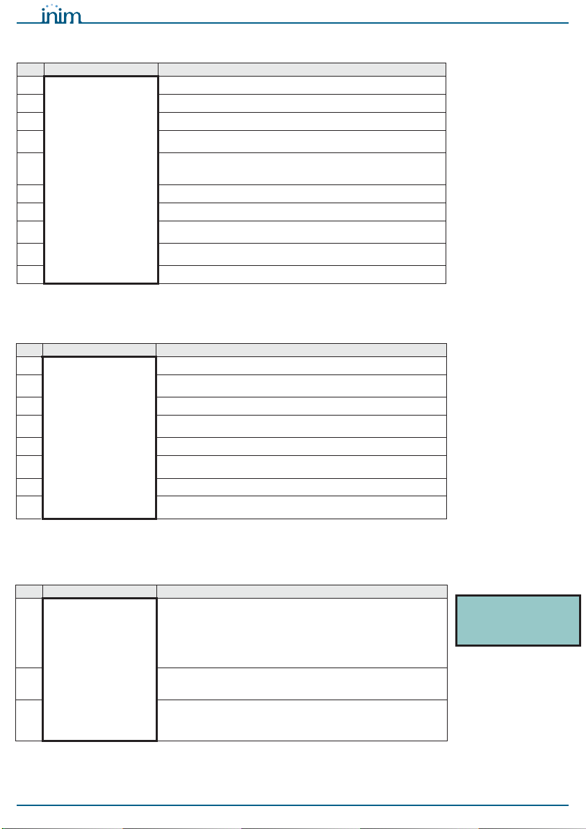
1. Connect just one device to the EDRV2000 driver, to the base (table 3, B) if it is a
detector, to the terminal board (table 3, A) if it is a module, call point or sounder.
2. Switch the driver ON using the OK/Read (table 3, H) button.
3. If you wish to know the address of the connected device press the OK/Read
(table 3, H) button.
If you wish to assign an address to the connected device, select the desired
address by means of the Up (table 3, J) or Down (table 3, K) button, then press
and hold the Esc/Write (table 3, I) button for at least 1 second to assign it.
In the case of multi-module devices, it is necessary first to select one of the mod-
ules it comprises.
5
Diagnoses of Enea analogue
devices
The EDRV2000 driver can be used to drive and control an entire loop of Enea
addressable devices by means of the addressing, diagnosis and configuration
procedures.
These procedured, when applied to an entire loop or even a single device, can be
carried out without having an Inim fire-detection control panel installed.
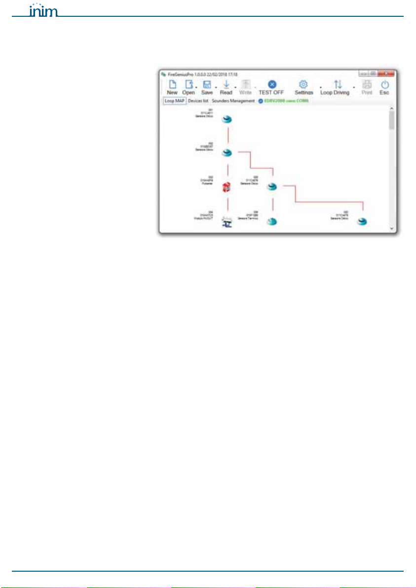
The diagnosis can be carried out in two ways:
• Using the buttons and display on the driver
• Using the FireGenius-PRO software
5-1
Diagnoses using the buttons and
display on the driver
In this way the appliance can operate using its own internal batteries.
If instead the EITK-PWSPS (included in the kit) is connected to the driver, the loop will
be powered by the same and the internal batteries will be placed into the process of
recharging.
1. Connect just one device to the EDRV2000 driver, to the base (table 3, B) if it is a
detector, to the terminal board (table 3, A) if it is a module, call point or sounder
of an entire loop.
2. Switch the driver ON using the OK/Read (table 3, H) button.
3. Press and hold the OK/Read button again to access the main menu of the driver.
4. Select the “Device Info” option for the diagnosis of a single device connected to
the appliance, select the “Loop” option in the case of several devices (loop or
conventional line).
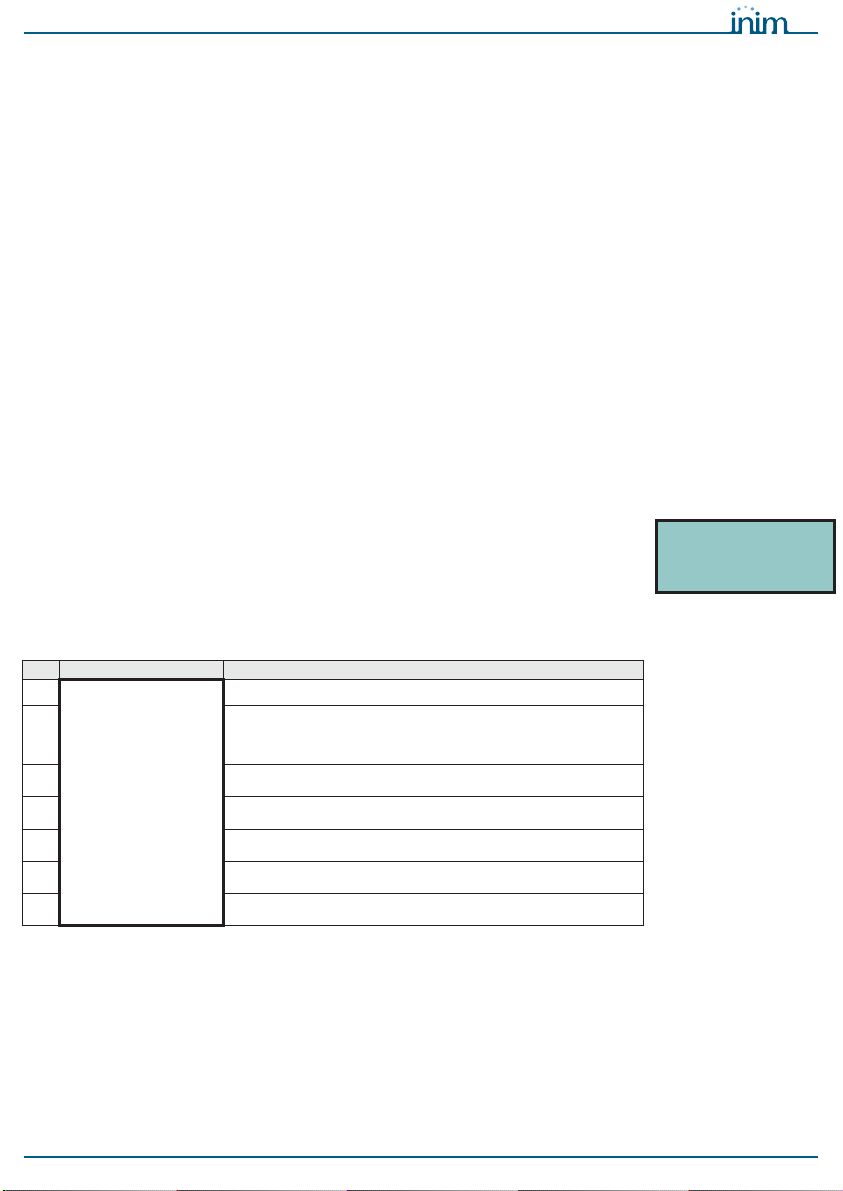
DEVICE INFO
From the “Device Info” option on the menu it is possible to access the management
menu of the devices connected to the driver.
This menu can also be reached by using the OK button to select a single device from
among those listed after a loop has been read (refer to the “Loop” option).
>Device Info
Loop
ICP Port
EDRV2000
>S/N xxxxxxxxx
Address yyy
Detector
LED ON