Primes FocusParameterMonitor FPM 60 User manual
Revision 06 EN 02/2023
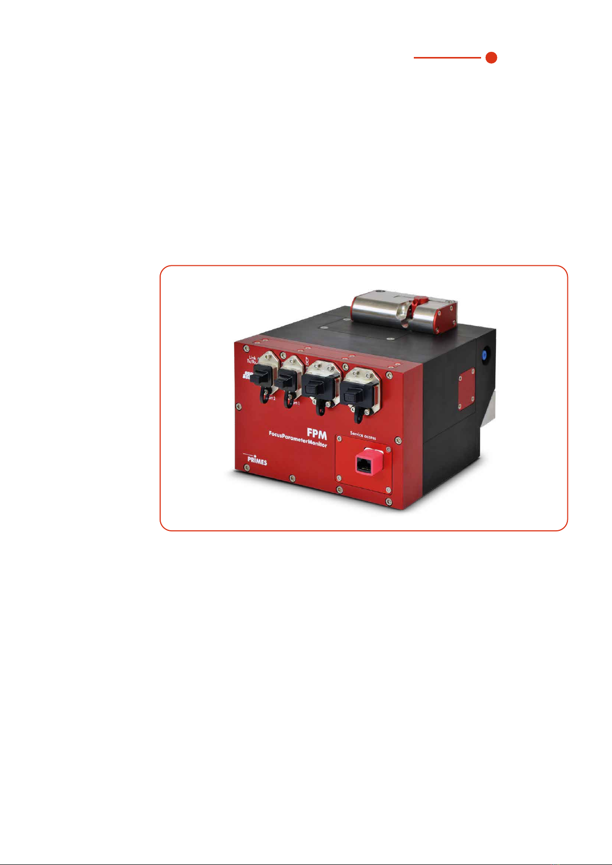
FocusParameterMonitor FPM
FPM60, FPM100, FPM160
Hardware and software interface PROFINET®/PROFIBUS®
35,0(6
Original Instructions


3
Revision 06 EN 02/2023
35,0(6
IMPORTANT!
READ CAREFULLY BEFORE USE!
KEEP FOR FUTURE USE!

4Revision 06 EN 02/2023
FocusParameterMonitor FPM
35,0(6
Inhaltsverzeichnis
1 Basic safety notes 7
2 Symbols and conventions 8
3 About this operating manual 9
4 Device description 10
4.1 Type overview .........................................................................................................................10
4.2 Functional description .............................................................................................................11
4.3 Measuring principle .................................................................................................................12
4.4 Optical displays.......................................................................................................................13
4.4.1 FPM PROFIBUS®.....................................................................................................13
4.4.2 FPM PROFINET®.....................................................................................................13
4.4.3 FPM PROFINET®M12 ..............................................................................................14
4.5 Scope of delivery and optional accessories .............................................................................14
5 Transport and storage 15
6 Mounting 15
6.1 Conditions at the installation site .............................................................................................15
6.2 Installation in the laser system .................................................................................................15
6.2.1 Prepare mounting .....................................................................................................15
6.2.2 Possible mounting positions......................................................................................16
6.2.3 Align the device ........................................................................................................16
6.2.4 Mount the device ......................................................................................................17
6.3 Removal from the laser system................................................................................................19
7 Connections 20
7.1 FPM PROFIBUS®...................................................................................................................20
7.1.1 Interface description PROFIBUS®.............................................................................20
7.1.2 Set PROFIBUS® address .........................................................................................21
7.1.3 Device master file (GSD data)....................................................................................22
7.2 FPM PROFINET®....................................................................................................................23
7.2.1 Interface description PROFINET®.............................................................................23
7.2.2 Device master file (GSDML file) .................................................................................24
7.3 FPM PROFINET®M12.............................................................................................................25
7.3.1 Interface description PROFINET®M12 ......................................................................25
7.3.2 Device master file (GSDML data)...............................................................................27
7.4 Locking device for interlock.....................................................................................................27
7.5 Compressed Air Connection ...................................................................................................28
8 PROFIBUS®-/PROFINET® parameter set 29
8.1 Inputs......................................................................................................................................30
8.2 Outputs...................................................................................................................................33
8.3 Error identifier..........................................................................................................................35
8.3.1 Error identifier hardware ............................................................................................35
8.3.2 Error identifier parameter selection ............................................................................35
8.3.3 Error identifier single plane measurement ..................................................................36
8.3.4 Error identifier caustic................................................................................................36
8.3.5 Warning identifier single plane measurement.............................................................37
8.3.6 Warning identifier caustic ..........................................................................................37
9 Install and configure LDS 38
9.1 System requirements ..............................................................................................................38
9.2 Install software ........................................................................................................................38

5
Revision 06 EN 02/2023
35,0(6
9.3 Ethernet configuration .............................................................................................................39
9.3.1 Set IP address of PC ................................................................................................39
9.3.2 Change IP address of a connected device ................................................................39
9.3.3 Establishing a connection to FPM .............................................................................40
9.3.4 Obtain an IP address automatically with DHCP .........................................................41
10 Description of the LDS 42
10.1 Graphical user interface...........................................................................................................42
10.1.1 The menu bar ...........................................................................................................43
10.1.2 The toolbar ...............................................................................................................44
10.1.3 Menu overview..........................................................................................................45
11 Measurement settings 47
11.1 Warning messages..................................................................................................................47
11.2 Enter measurement parameters with the LDS .........................................................................48
11.2.1 Establish connection.................................................................................................48
11.2.2 Sensor parameters ...................................................................................................48
11.2.3 Measurement window...............................................................................................49
11.2.4 The command line „Command“ ................................................................................50
11.2.5 Creating setups ........................................................................................................51
11.2.6 Checking the beam position .....................................................................................52
11.3 Enter measurement parameters via the PLC ...........................................................................52
11.4 Determine exposure time with the help of the LDS ..................................................................53
11.4.1 Preparation ...............................................................................................................53
11.4.2 Triggering a manual measurement ............................................................................53
11.4.3 Setting the gain.........................................................................................................54
11.5 Determine the exposure time via the PLC................................................................................55
12 Measuring 61
12.1 Measuring procedure ..............................................................................................................61
12.1.1 Measuring procedure power measurement ...............................................................61
12.1.2 Measuring procedure focus measurement (untriggered) ............................................62
12.1.3 Measuring procedure focus measurement (triggered)................................................63
12.1.4 Measuring procedure caustic measurement..............................................................64
12.1.5 Measuring procedure combined measurement .........................................................65
12.2 Timing diagrams .....................................................................................................................66
12.2.1 Timing diagram power measurement ........................................................................66
12.2.2 Timing diagram focus measurement (untriggered).....................................................67
12.2.3 Timing diagram focus measurement (triggered).........................................................69
12.2.4 Timing diagram caustic measurement.......................................................................71
12.2.5 Timing diagram combined measurement ..................................................................72
12.3 Flow Chart combined measurement........................................................................................75
13 Display of a measurement in the web browser 77
14 Maintenance and Service 79
14.1 Maintenance intervals..............................................................................................................79
14.2 Cleaning..................................................................................................................................79
14.3 Spare parts .............................................................................................................................79
14.4 Maintenance of the Protective Window ...................................................................................80
14.4.1 Exchange of the protective window cartridge............................................................81
14.4.2 Exchanging or cleaning of the protective window......................................................82
15 Measures for the product disposal 83
16 Declaration of incorporation for partly completed machine 84
17 Technical Data 85
18 Dimensions 86

6Revision 06 EN 02/2023
FocusParameterMonitor FPM
35,0(6
PRIMES - the company
PRIMES is a manufacturer of measuring devices which are used to analyze laser beams. These devices are
employed for the diagnostics of high-power lasers ranging from CO2-, fiber- and solid-state lasers to diode
lasers. A wavelength range from infrared through to near UV is covered, offering a wide variety of measuring
devices to determine the following beam parameters:
• Laser power
• Beam dimensions and position of an unfocused beam
• Beam dimensions and position of a focused beam
• Beam quality factor M²
Development, production and calibration of the measuring devices is performed at PRIMES. This guarantees
optimum quality, excellent service, and a short reaction time, providing the basis for us to meet all of our
customers’ requirements quickly and reliably.
PRIMES GmbH
Max-Planck-Str. 2
64319 Pfungstadt
Germany
Tel +49 6157 9878-0
www.primes.de

7
Revision 06 EN 02/2023
Basic safety notes
35,0(6
1 Basic safety notes
Intended use
The device has been designed exclusively for measurements in the beam of high-power lasers.
Use for any other purpose is considered as not intended and is strictly prohibited. Furthermore, intended use
requires that all information, instructions, safety notes and warning messages in this operating manual are
observed. The specifications given in chapter17 „Technical Data“ on page85 apply. Any given limit values
must be complied with.
If not used as intended, the device or the system in which the device is installed can be damaged or
destroyed. In addition, there is an increased risk to health and life. Only use the device in such a way that
there is no risk of injury.
This operating manual is an integral part of the device and must be kept in the immediate vicinity of the place
of use, accessible to personnel at all times.
Every person who is responsible for the installation, start-up or operation of the device must have read and
understood the operating manual and, in particular, the safety instructions.
If you still have questions after reading this operating manual, please contact PRIMES or your supplier for
your own safety.
Observing applicable safety regulations
Observe the safety-relevant laws, guidelines, standards and regulations in the current editions published by
the state, standardization organizations, professional associations, etc. In particular, observe the regulations
on laser safety as well as machine safety and comply with their requirements.
Before commissioning, it must be ensured that the entire machine in which the device is installed meets
these safety requirements. Otherwise the commissioning of the device is prohibited.
Necessary safety measures
The device measures direct laser radiation, but does not emit any radiation itself. However, during the mea-
surement the laser beam is directed at the device. This produces scattered or directed reflection of the laser
beam (laser class 4). The reflected beam is usually not visible.
Protect yourself from direct and reflected laser radiation while working with the device by taking the following
measures:
• Wear safety goggles adapted to the power, power density, laser wavelength and operating mode of the
laser beam source in use.
• Wear suitable protective clothing or protective gloves if necessary.
• If possible, also protect yourself from direct laser radiation and scattered radiation by using separating
protective devices that block or attenuate the radiation.
• If the device is moved from its aligned position, increased scattered or directed reflection of the laser
beam occurs during measuring operation. Mount the device in such a way that it cannot be moved unin-
tentionally, i.e. by bumping or pulling the cables.
• Install safety switches or emergency safety mechanisms that allow the laser to be switched off immedi-
ately.
• Use suitable beam guidance and beam absorber elements which do not emit any hazardous substances
when irradiated.
Employing qualified personnel
The device may only be operated by qualified personnel. The qualified personnel must have been instructed
in the installation and operation of the device and must have a basic understanding of working with high-
power lasers, beam guiding systems and focusing units.
8Revision 06 EN 02/2023
FocusParameterMonitor FPM
35,0(6
Conversions and modifications
The device may not be modified in terms of design or safety without the explicit consent of the manufacturer.
The same applies to unauthorized opening, dismantling and repair. The removal of covers is only permitted
within the scope of the intended use.
Liability disclaimer
Manufacturer and distributor exclude any liability for damages and injuries which are direct or indirect con-
sequences of using the device not as intended or modifying the device or the associated software without
authorization.
2 Symbols and conventions
Warning messages
The following icons and signal words indicate possible residual risks in the form of warnings:
DANGER
Means that death or serious physical injuries will occur if necessary safety precautions are not
taken.
WARNING
Means that death or serious physical injuries may occur if necessary safety precautions are not
taken.
CAUTION
Means that minor physical injury may occur if necessary safety precautions are not taken.
NOTICE
Means that property damage may occur if necessary safety precautions are not taken.
Product safety labels
The following icons are used on the device itself to indicate imperatives and possible dangers:
General warning sign
Read and understand the operating manual before using the device!
Labeling according to WEEE directive:
The device must not be disposed of with household waste, but in a separate WEEE collection
in an environmentally friendly way.

9
Revision 06 EN 02/2023
About this operating manual
35,0(6
Further icons and conventions in this operating manual
Here you will find useful information and helpful tips.
Indicates a single instruction.
If several of these instructions appear one below the other, the order in which they are executed is
irrelevant or they represent alternative courses of action.
1.
2.
...
A numbered list identifies a sequence of instructions that must be executed in the specified order.
Indicates the result of an action to explain processes that take place in the background.
Indicates an observation prompt to draw attention to visible feedback from the device or the software.
Observation prompts make it easier to check whether an instruction was executed successfully.
Often they also guide to the next instruction.
Points to a control element that is to be pressed/clicked.
Points to an element described in the text (for example an input field).
3 About this operating manual
This manual describes working with the FocusParameterMonitor FPM and its settings both
• via a system using a PLC
• as well as with the LaserDiagnosticsSoftware LDS 2.98.
The FocusParameterMonitor FPM is intended to be used with a PLC for fully automated operation. Manual
operation with a PC is not recommended.
However, since the FocusParameterMonitor FPM is designed for measuring short-term exposure and does
not automatically adjust the exposure time, the appropriate exposure time must be determined for the
various beam configurations. The LaserDiagnosticsSoftware LDS 2.98 can be used for setup.
The LaserDiagnosticsSoftware LDS 2.98 is available free of charge on the PRIMES website at:
https://www.primes.de/de/support/downloads/software.html.
In these operating manual, the abbreviations FPM and LDS will be used in the following.
10 Revision 06 EN 02/2023
FocusParameterMonitor FPM
35,0(6
4 Device description
4.1 Type overview
The digits in the name indicate different types. These differ in their maximum permissible divergence as well
as the imaging scale.
• FocusParameterMonitor FPM 60 with a maximum divergence of 60 mrad and a 1:1 image
• FocusParameterMonitor FPM 100 with a maximum divergence of 100 mrad and a 5:1 image
• FocusParameterMonitor FPM 160 with a maximum divergence of 160 mrad and a 3:1 image
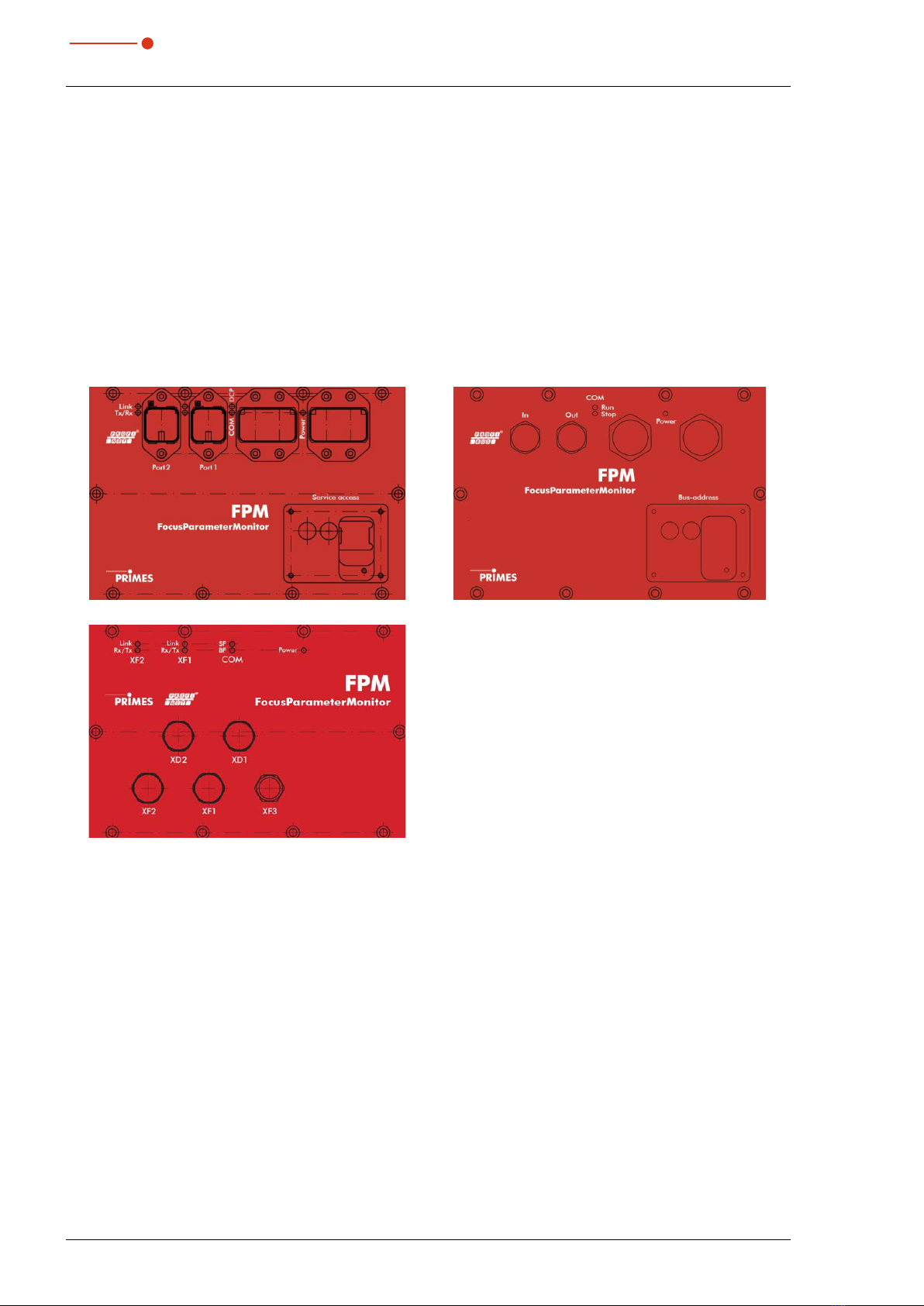
The FPM is optionally equipped with a PROFIBUS®or a PROFINET®interface. For this purpose the following
connection fields are available:
PROFINET®PROFIBUS®
PROFINET®M12
The following variants of the FPM are available:
• FPM 60 PROFIBUS®
• FPM 60 PROFINET®
• FPM 100 PROFIBUS®
• FPM 100 PROFINET®
• FPM 100 PROFINET®M12
• FPM 160 PROFIBUS®
• FPM 160 PROFINET®
• FPM 160 PROFINET®M12
Devices with PROFINET
®
and PROFIBUS
®
connection field are available with an openly accessible or a con-
cealed Ethernet port.
For PROFINET®M12 devices, the Ethernet port XF3 is always freely accessible.

11
Revision 06 EN 02/2023
Device description
35,0(6
4.2 Functional description
The FPM is designed for laser beam measurement. The beam quality is controlled by means of periodic
measurements which ensures the process quality. The following parameters are measured:
• Laser power
• Power density distribution
• Beam position and beam geometry
• Caustic of laser beams
The FPM consists of three main components: the power measuring unit, the beam analysis unit and the
PROFIBUS®or PROFINET®interface. These components are included in a stable aluminium housing.
An electrically operated shutter protects the beam entrance from pollution.
In addition, an exchangeable protective window is integrated. It is constantly surrounded by compressed air.
The compressed air is required to create an overpressure in the housing, which prevents the penetration of
dirt particles.
PROFIBUS®/
PROFINET®
Interface
FocusParameterMonitor FPM
+24 V
Beam Analysis
Power
Measurement
Control
Data
Fig. 4.1: Block diagram of the FPM

12 Revision 06 EN 02/2023
FocusParameterMonitor FPM
35,0(6
4.3 Measuring principle
The device determines the laser power in the power measuring unit according to the calorimetric principle.
For this purpose the absorber of the power measuring unit is irradiated with the laser for a defined time.
Using the known absorber mass and the specific heat capacity of the absorber material, the introduced
energy can be calculated by the measured temperature increase. The measured exposure time can then be
used to calculate the power.
The beam geometry and the power density distribution are measured by the camera-based beam analysis
unit using a CCD sensor. The measurement of beam parameters require an external z-axis.
The measurement data is transmitted to the system control via a PROFIBUS®or PROFINET®interface.
The beam coming from the laser is transmitted through the beam entrance to deflection mirror 1 and from
there to a beam splitter.
The lagest part of the beam enters an absorber which is part of the power measurement unit.
The attenuated beam reaches the beam analysis unit (CCD sensor) via deflecting mirror 2.
The power measuring unit is used to determine the power and the beam analysis unit is used to measure the
beam position and geometry, the caustic and the power density distribution.
Shutter
Measuring Position
Measurement level
Entrance level
Deflection Mirror 1
Protective Window
Cartridge
Beam Splitter
Deflection
Mirror 2
Absorber
CCD-Sensor Beam Entrance
Fig. 4.2: Beam path inside FPM
Please note that the measuring plane in the FPM is below the entrance plane, depending on the
magnification and the configuration. (see chapter17 „Technical Data“ on page85).
13
Revision 06 EN 02/2023
Device description
35,0(6
4.4 Optical displays
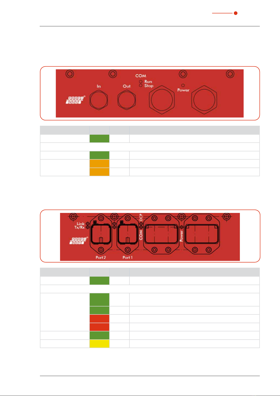
4.4.1 FPM PROFIBUS®
LED Color State Meaning
Power Green On Supply voltage applied.
COM Run Green On Communication takes place on the bus.
COM Stop
Orange On There is a connection, but no data is exchanged.
Orange Blinks The measuring device has no physical connection to the bus.
Tab. 4.1: Light signals and colors PROFIBUS®
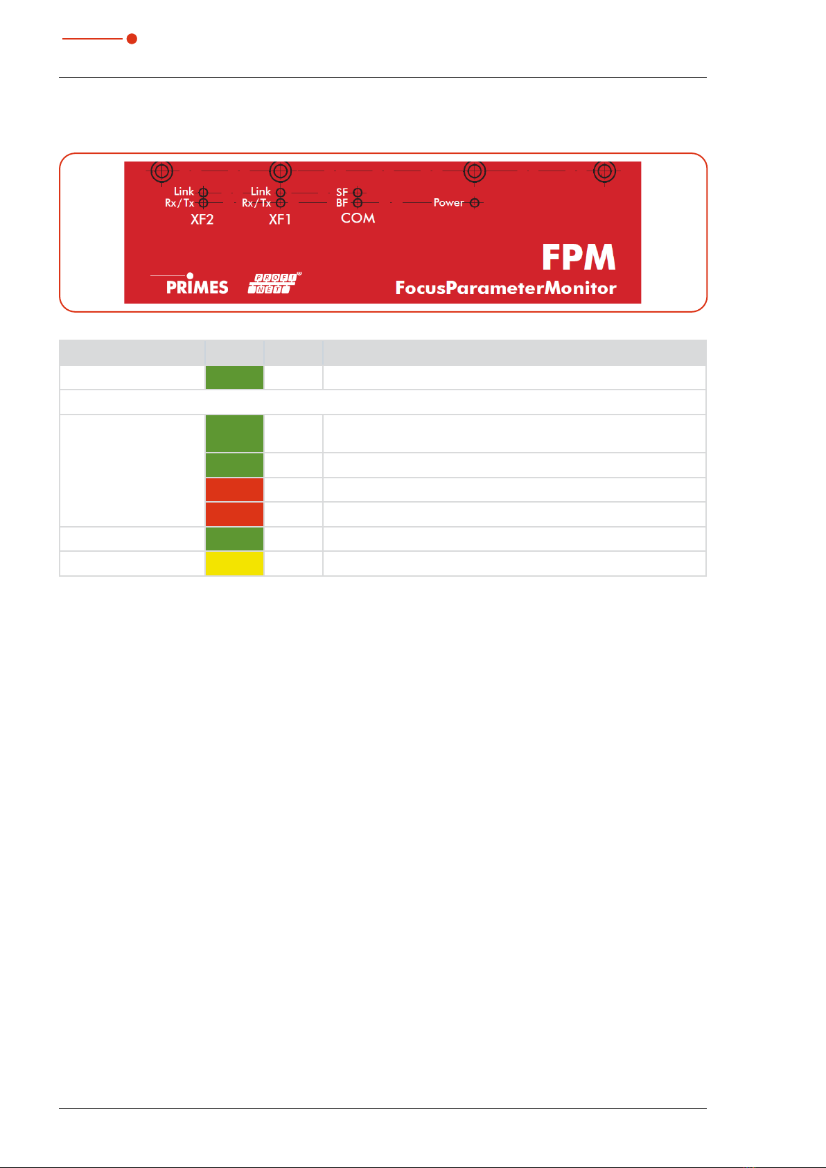
4.4.2 FPM PROFINET®
LED Color State Meaning
Power Green On Supply voltage applied.
COM
Green On Watchdog timeout or „Channel, generic or extended diagnostics
present“ or system error.
Green Blinks DCP signal service is triggered via the bus.
Red On
No configuration or slow physical connection or no physical connection.
Red Blinks No data exchange.
Link (Port 1 and Port 2)
Green On The device has a connection to the Ethernet.
Tx/Rx (Port 1 and Port 2)
Gelb Flickers The device sends/receives Ethernet frames.
Tab. 4.2: Light signals and colors PROFINET®
14 Revision 06 EN 02/2023
FocusParameterMonitor FPM
35,0(6
4.4.3 FPM PROFINET®M12
LED Color State Meaning
Power Green On Supply voltage applied.
COM
Green On Watchdog timeout or „Channel, generic or extended diagnostics
present“ or system error.
Grün Blinks DCP signal service is triggered via the bus.
Red On
No configuration or slow physical connection or no physical connection.
Red Blinks No data exchange.
Link (XF 1 and XF 2) Green On The device has a connection to the Ethernet.
Rx/Tx (XF 1 and XF 2) Gelb Flickers The device sends/receives Ethernet frames.
Tab. 4.3: Light signals and colors PROFINET®M12
4.5 Scope of delivery and optional accessories
The scope of delivery includes:
• FPM
• USB flash drive
• Operating manual (printed version)
The following accessories are optional:
• Transport and storage case
• Maintenance hatch with passage for Ethernet

15
Revision 06 EN 02/2023
Transport and storage
35,0(6
5 Transport and storage
NOTICE
Damage/destruction of the device
Hard impacts or dropping can damage the optical components.
Handle the measuring device carefully during transport and installation.
6 Mounting
DANGER
Serious eye or skin injury due to laser radiation
A
n improper installation by unqualified personnel can lead to material damage or even personal injury.
Have the device installed by qualified personnel only. Qualified personnel must have basic knowledge
about working with high-power lasers, beam delivery systems and focusing units.
6.1 Conditions at the installation site
• The device must not be operated in a condensing atmosphere.
• The ambient air must be free of gases and aerosols that interfere with the laser radiation (e.g. organic
solvents, cigarette smoke, sulfur hexafluoride).
• Protect the device from splashes of water and dust.
• Operate the device in closed rooms only.
6.2 Installation in the laser system
The FPM is intended for the installation into a laser system. Therefore neither constructive nor safety related
modifications may be made to the FPM unless we have given our explicit written consent. In case of any
modifications, we do not accept any liability for resulting damages.
6.2.1 Prepare mounting
NOTICE
Damaging/destroying the device
Too little space in front of the shutter can damage the device.
Make sure that there is enough free space to open the shutter.
1. Switch off the laser beam.
2. Ensure that moving parts, e.g. robot arms, etc. are at a standstill and that they cannot be set in motion
unintentionally.
3. Check the space available before installing the device, especially the required space for the connection
cables and hoses/shutter.

16 Revision 06 EN 02/2023
FocusParameterMonitor FPM
35,0(6
6.2.2 Possible mounting positions
The FPM can be mounted both horizontally and vertically. Due to the danger of contamination we recommend
a vertical mounting with a horizontal beam incidence. The plug connections should point downwards and
unused sockets should be covered with the caps supplied.
6.2.3 Align the device
DANGER
Serious eye or skin injury due to laser radiation
If the device is moved from its aligned position, increased scattered or directed reflection of
the laser beam occurs during measuring operation (laser class 4).
Mount the device so that it cannot be moved by an unintended push or a pull on cables.
The device must be aligned to the laser beam. The laser beam must hit the centre of the inlet aperture.
Please mind and adhere to the specifications and limit values given in chapter „17 Technical Data“ on
page 85. The distance between the measurement plane and the entrance plane can be up to 25 mm,
depending on the lens.
The marking on the shutter can be used as an alignment aid. Align the device using the pilot beam with the
shutter closed.
In order to avoid direct reflections into the laser system, the device can be installed offset at an
angle of max. 10mrad to the incoming beam.
17
Revision 06 EN 02/2023
Mounting
35,0(6
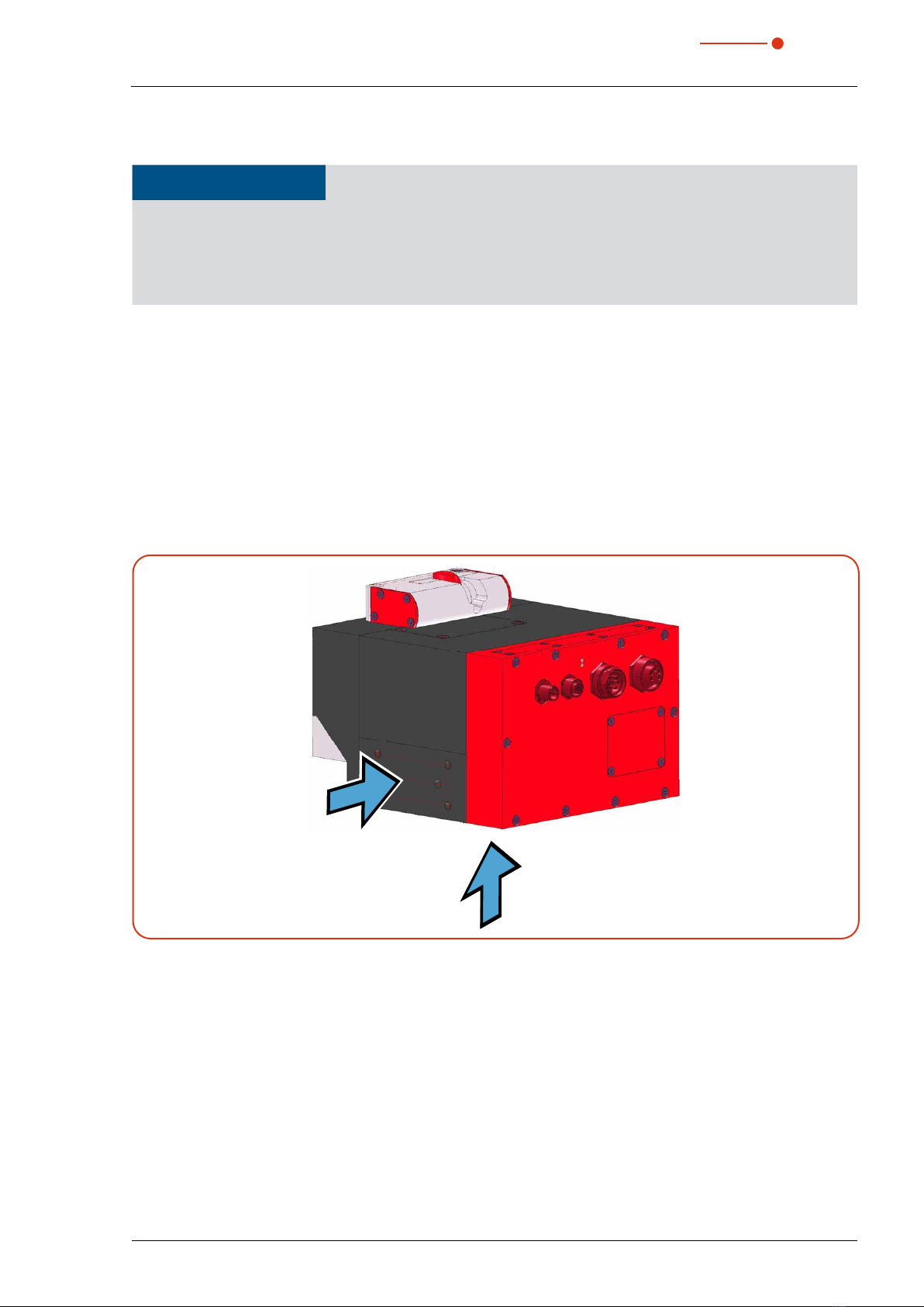
6.2.4 Mount the device
NOTICE
Damaging/destroying the device
Screws which are too long can damage the screw-in thread.
When choosing the mounting screws, please ensure that the maximum extension into the device
does not exceed 12 mm.
• Mount the device securely in order to prevent a relative movement to the beam axis, reducing a danger
posed by scattered radiation.
• Mounting space: Please note that the shutter of the FPM is opened and closed during operation. A com-
plete opening of the shutter has to be ensured. Please make sure that there is enough space to prevent
a collision of the shutter with other parts of the machine as well as to exclude a hazard for the operating
personnel by crushing.
In the base plate of the housing (A) as well as in the side wall (B) there are four fastening threads M6 for
the fixture on a customer specific mounting (see Fig. 6.2 and Fig. 6.3 ). Please mount the housing with four
screws M6. We recommend screws of the strength class 8.8 and a tightening torque of 35N∙m.
There are also two dowel pin holes Ø6 H7x10 each in the base and in the side panel for precise and reproducible
alignment of the unit.
A
B
Fig. 6.1: Mounting options on the FPM
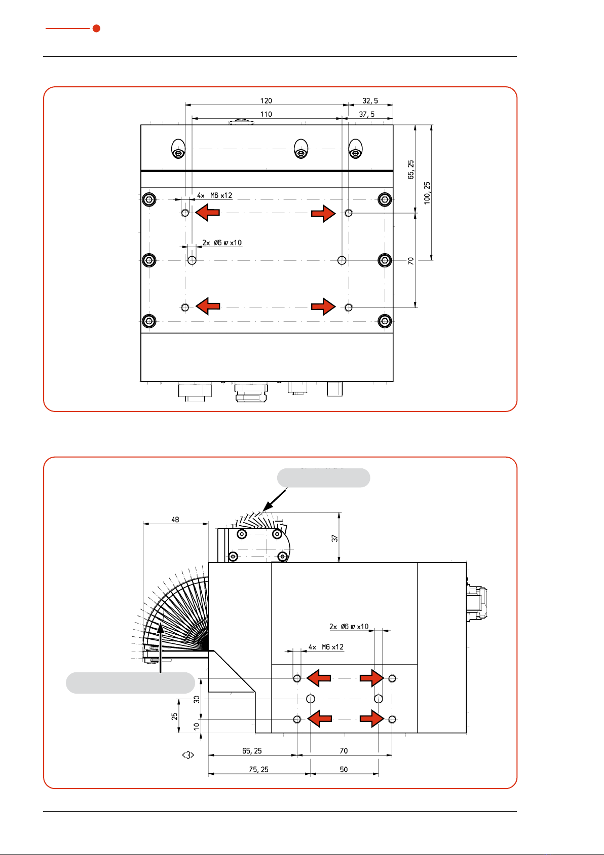
18 Revision 06 EN 02/2023
FocusParameterMonitor FPM
35,0(6
Fig. 6.2: Mounting hole in the base plate (view A)
Movement range
shutter
Movement range
protective window cartridge
Fig. 6.3: Mounting holes in the side wall (view B)

19
Revision 06 EN 02/2023
Mounting
35,0(6
6.3 Removal from the laser system
CAUTION
Damage to hearing
If the compressed air hose is loosened while still under pressure, this generates noise. This can
cause hearing damage.
Only loosen the compressed air hose when there is no longer any pressure.
1. Switch off the laser beam.
2. Ensure that moving parts, e.g. robot arms, etc. are at a standstill and that they cannot be set in motion
unintentionally.
3. Close the shutter.
4. Disconnect the device from the power supply.
5. Switch off the compressed air supply.
6. Disconnect all connections.
7. Unscrew the mounting screws.
8. Remove the device from the laser system.
20 Revision 06 EN 02/2023
FocusParameterMonitor FPM
35,0(6
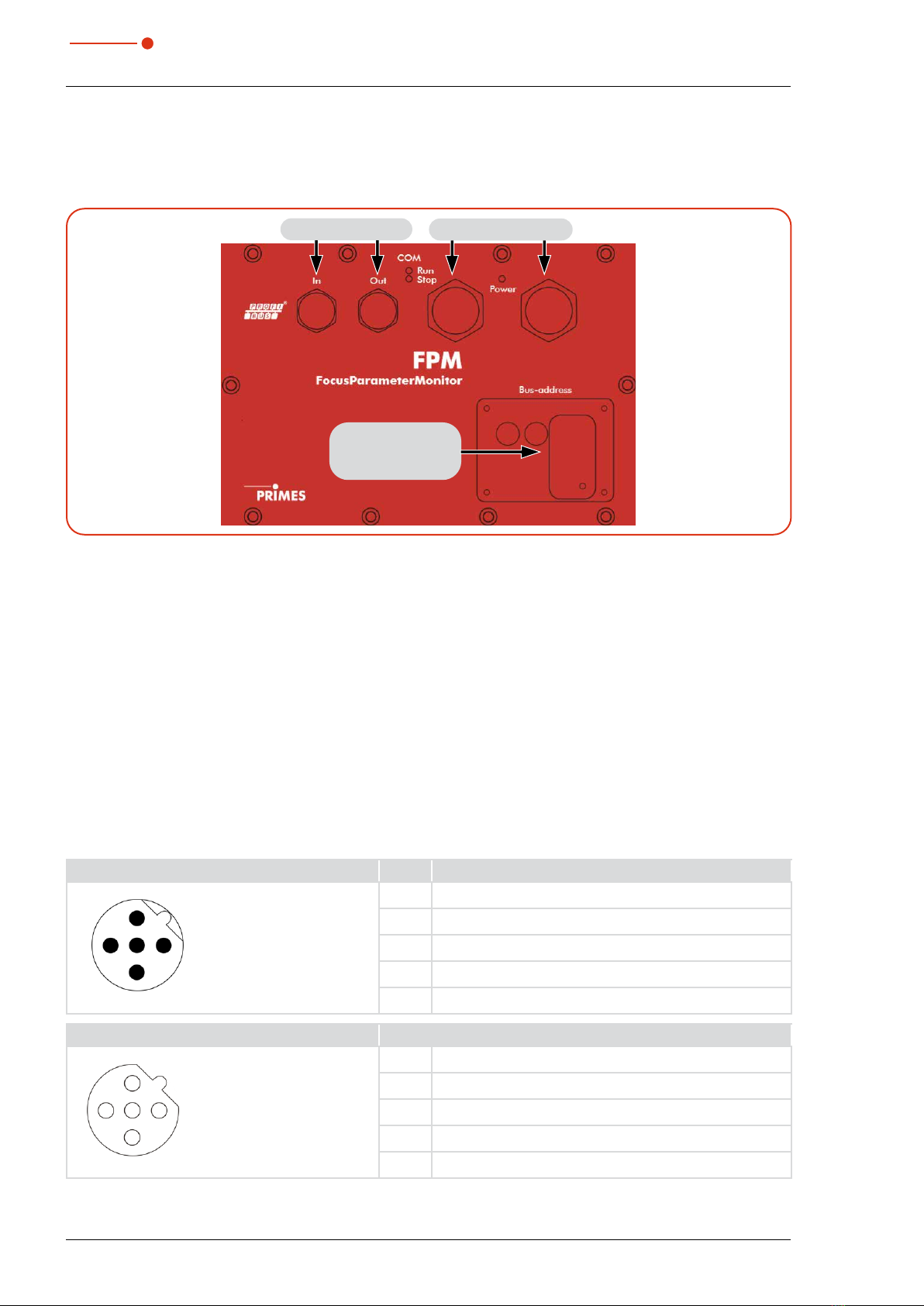
7 Connections
7.1 FPM PROFIBUS®
Fig. 7.1:
Maintenance hatch
with Ethernet port
PROFIBUS In/Out Voltage supply
Connections FPM PROFIBUS®
7.1.1 Interface description PROFIBUS®
Both the bus interface and the power supply are duplicated so that the FPM can be inserted into a line structure.
There are five interfaces in total:
• 2 x PROFIBUS®ports
• 2 x 24V power supplies (24V ± 5%, max. 500mA)
• 1 x Ethernet port
The data are stored in registers in Motorola format. This means that high bytes are stored first and the lower
bytes follow on the next registers.
PROFIBUS®(In/Out)
The plug or socket for PROFIBUS®is a 5-pole, B-coded M12 connector.
Pin assignment plug (top view mating side) Pin Funktion
1
4
2
5
3
1 Not connected
2 Signal A
3 Not connected
4 Signal B
5 Not connected
Pin assignment socket (top view mating side) Pin Function
2
4
1
5
3
1 +5V
2 Signal A
3 ISOGND
4 Signal B
5 Not connected
Tab. 7.1: Connectors PROFIBUS®
This manual suits for next models
2
Table of contents
Other Primes Diagnostic Equipment manuals


