Initiative Engineering edose User manual

OPERATION AND MAINTENANCE MANUAL
www.initiativeengineering.com
FORMAT NO- IE/00/15(2)
REV. DATE 01-08-19
REV. NO. 00
IP 65
IP 65

www.initiativeengineering.com
FEATURES
ŸPTFE diaphragm for longer life.
ŸBuilt in air release valve (ARV).
ŸAdjustable frequency (up to 400 spm) with a frequency knob.
ŸAuto reseng thermal fuse.
ŸSplash proof enclosure.
ŸDouble ball NRV with PTFE seal.
ŸIP 65 cerfied.
ŸCompact and lightweight.
PAGE 1
SCOPE OF SUPPLY
ŸMetering pump.
ŸSucon/discharge tubing (3 meter).
ŸFoot valve with strainer.
ŸInjecon valve (NRV).

www.initiativeengineering.com
PAGE 2
SPECIFICATIONS
Dosing
LPH
6
10
Mechanical
Data
Turn Down Ratio
10:1
Maximum Dosing
Capacity
l/h
7.8
13
GPH
2.06
3.43
Minimum Dosing
Capacity
l/h
0.6
1.0
GPH
0.16
0.26
Maximum
Operating Pressure
Kg/cm²
4
PSI
57
Maximum Stroke
Frequency
strokes/min.
400
430
Stroke Volume
ml
0.28
0.4
Accuracy of
Repeatability
%
±2
Maximum Suction
Lift During
Operation
meter
1.5
Min. / Max. Liquid
Temperature
⁰C
5 to 50
Suction / Discharge
Tubing
mm
4/6
Electrical
Data
Voltage
V
230 ± 10%
Frequency
Hz
50 – 60
Length of Main
Cable
meter
2
Maximum Power
Consumption
W
30
Electric Safety Class
II
Enclosure Class
IP 65
Pollution Degree
3
Sound
Pressure
Maximum Sound
Pressure
dB
‹80

www.initiativeengineering.com
PAGE 3
INSTALLATION
(8) Mount the pump on a tank/surface using mounng bracket and nut-bolts provided and ghten
the nut-bolts properly.
(1) Always wear protecve clothing, face shield, safety glasses and gloves when working on or near
your metering pump. Addional precauons should be taken depending on the soluon being
pumped.
(11) Aer cung an appropriate length of tubing, connect tubing to injecon valve and then back to
the discharge side of the pump head.
(13) Connect the nozzle on the pump to the injecon valve.
(4) Sucon li -: Sucon li should be less than 1.5 meter for soluons having a specific gravity of
water, for denser soluons consult factory.
(10) The sucon nipple will be on the lower side with the sucon tubing being immersed completely
in the dosing liquid.
(3) Flooded sucon -: The pump is mounted at the base level of the storage tank. This installaon is
most trouble free and is recommended for low flow output and high viscosity soluons. Since
sucon tubing is filled with soluon, priming is accomplished quickly and chance of losing prime
is reduced.
(6) The valve is designed to submerge in the soluon tank or drum and must sit in a vercal posion
at the boom. Posion approximately 2 inches off the boom if the tank or drum contains
sediment.
(2) Pump is to be protected from sun and rain. If outdoor installaon is unavoidable, provide a
canopy over the pump. Pump should be accessible for roune maintenance and should not be
subjected to ambient temperature above 50° C.
(7) Injecon valve prevents back flow from the main line. When installing the injecon valve, be sure
to posion it in vercal so that the valve enters the boom of the pipe line.
(5) The foot valve act as a check valve to keep the pump primed in sucon li applicaons.
(9) The discharge point marked with arrow should be always faces upwards.
(12) Use the remaining tubing on the discharge side and connect the back injecon valve to the
injecon pipe into which dosing is to be done.
(14) Plug the pump.

www.initiativeengineering.com
PAGE 4
STARTUP
(5) Keep the ARV open unl the dosing liquid flows in a connuous stream in the tubing (without any
bubbles).
(1) Connect the mains supply.
(3) Switch on the mains buon and press the on-off key of the pump to start the pump.
(6) Close the ARV.
(2) Turn the frequency knob fully in clockwise direcon to 100 (max. frequency seng of the pump).
(4) Open the ARV (Air Release Valve) by approximately three-five turns.
MOUNTING SET-UP SCHEMATIC
INJECTION VALVE
MAIN LINE
CHEMICAL TANK

www.initiativeengineering.com
PAGE 5
DOSING HEAD ASSEMBLY
Sr. No
DESCRIPTION
1
DIAPHRAGM (PTFE)
2
DIAPHRAGM “O” RING
3
DOSING HEAD
4
ARV
5
NRV BALL CAP
6
6mm BALL (BOROSILICATE)
7
NRV WASHER BIG (PTFE)
8
NRV WASHER SMALL (PTFE)
9
NRV BODY
10
NRV “O” RING
11
NRV NOZZLE
12
TUBING CAP
13
TUBING CONNECTOR
14
BOLT HEAD CAP
15
DOSING HEAD BOLT (M4X40)
16
HEAD BOLT WASHER (M4)
17
STAR WASHER
18
BALL SEAL (VT)
19
6mm BALL (BOROSILICATE)
20
NRV BALL CAP DISCHARGE

www.initiativeengineering.com
PAGE 6
Sr. No
DESCRIPTION
1
PCB HOUSING
2
SS PLUNGER
3
SOLENOID ASSEMBLY
4
SOLENOID HOUSING
5
DOSING HEAD
6
SS SPRING
7
DIAPHRAGM
8
MOUNTING BRACKET
9
SOLENOID SPACER
GENERAL ASSEMBLY DRAWING
SECTION VIEW
NOTE : ALL DIMENSIONS ARE IN MM

www.initiativeengineering.com
PAGE 7
EXPLODED VIEW
(ALL DETAILS SHOWN IN THE MANUAL ARE SUBJECTED TO CHANGE WITH/WITHOUT NOTICE)

www.initiativeengineering.com
PAGE 8
PART LIST
PART NO. DESCRIPTIONSR. NO.
P16

www.initiativeengineering.com
PAGE 9
ESSENTIAL SAFETY REQUIREMENT
Ÿ Install the pump in any shaded place away from direct sunlight.
Ÿ Electrical connecon should be made between Live – Neutral and Not live-Ground.
Ÿ Make sure that any chemicals that are released from the pump or any damaged lines do not causes damages to
system parts.
Ÿ Ensure voltage is within range specified for the pump i.e., 230 ±10% V.
Ÿ Avoid giving supply from the same line as heavy electrical equipment.
Ÿ When working with chemicals, the accident pretension regulaons applicable at the installaon site should be
applied (e.g. wearing protecon clothing's). Observe the chemical manufacturer's safety data sheet and safety
instrucons when handling chemicals.
Ÿ The pump can not be used fin sub-merged condion.
Ÿ The dosing medium must be a liquid, Observe the freezing and boiling point of the dosing media. The
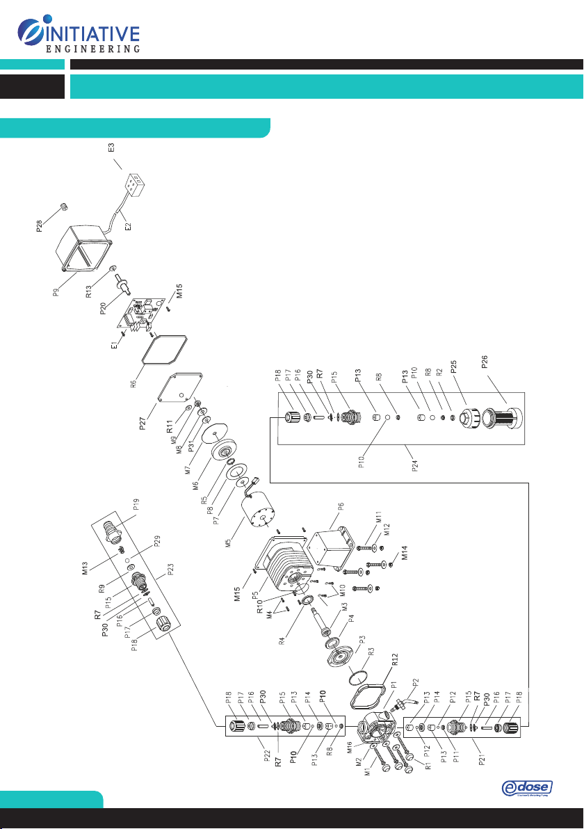
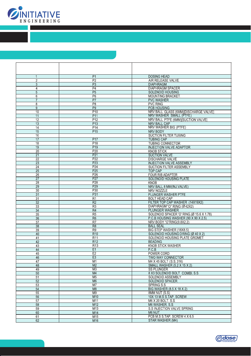
resistance of the parts which comes into contact with the dosing medium, such as the dosing head, PTFE ball
and washer, glass ball, 'O' ring, ball bush, pipe lines, ball seal and sucon filter assembly, NRV body etc. ,
depends on the medium, media temperature and operang pressure. Ensure that the parts come contact with
the dosing medium are resistance to the dosing medium under operang temperature and pressure, see the
data booklet.
Ÿ Before starng work on the pump, the pump must be disconnected from the power supply. The system must
be pressure less.
Ÿ Before switching on the main supply, the tubing cap (both sucon and discharge valve assembly) should be
ghtened to dosing head properly so that the metering liquid can not spray out from the dosing head in
working condion and put operator's in risk. The dosing medium/liquid is pressurized and can be harmful to
health and the environment.
6.Dismantle the sucon and discharge tubing and check whether tubing is blocked, soiled or damaged, replace if
necessary.
Ÿ Do not operate the pump with a damage/break diaphragm. Operang with damaged diaphragm can lead to
dosing liquid entering pump housing. In case of diaphragm breakage immediately separate the pump from the
power supply. Make sure the pump cannot be put back into the operaon by accident. In case of diaphragm
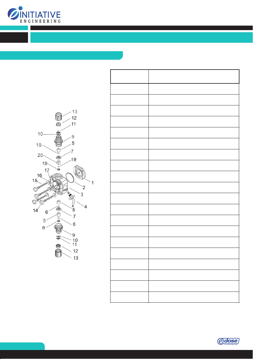
breakage use the following step to dismantle diaphragm (refer fig. of Edose Dosing Head overview):
1.Make the system pressure less.
2.Empty the dosing head before maintenance and flush it, if necessary.
3.Set the frequency knob to 0%.
4.Switch off mains supply.
5.Take suitable steps to ensure that the returning liquid is safely collected.
7.Dismantle NRV body in sucon and discharge side.

www.initiativeengineering.com
PAGE 10
8.Remove the ball bush and o ring from NRV body. Check their safety for wear and damage.
If necessary, replace them.
10.Remove the spring fing washer and nut and PTFE washer.
14.Check the diaphragm. If necessary, replace it.
9.Unscrew the PCB housing and remove it.
12.Remove the diaphragm washer, plunger washer and diaphragm o ring from diaphragm-plunger assembly.
13.Dismantle the diaphragm-plunger assembly
11.Loosen the screws on dosing head and remove the screws.

www.initiativeengineering.com
PAGE 11
Problem
Possible Causes
Trouble Shooting
Excessive Pump
Output
Syphoning
Little or no pressure at injection
point Excessive strokes per minute
Move injection point to a
pressurized point Make sure
injection check valve
installed properly Consult
factory
Pump will not
prime/loss priming
Pump not turned on or plugged in
No demand as per the set point.
Foot valve not in vertical position
in the tank. Pump suction lift is too
high Suction tubing is curved or
coiled inside the tank Air trap in
suction tubing
No solution in the tank/container
Airlock on suction side
Turn on the pump/plug in
Prime the pump in manual mode
Foot valve must be vertical
Maximum suction lift is 5 feet.
Suction tubing must be vertical
Untighten the air bleed valve, run
the pump till air trap is out then
tighten. Refill the container/tank
and re-prime Check tubing for
pinholes, cracks, replace if
necessary
Low output or
failure to pump
against pressure
Pump maximum pressure rating
exceeded by injection Worn seal
rings & balls Ruptured diaphragm
Tubing run on the discharge side
may be too long
Clogged foot valve strainer
Injection pressure cannot exceed
pump rated pressure Check &
replace Check & replace Longer
tubing may create frictional losses
sufficient to reduce pump pressure
rating Clean or replace
TROUBLE SHOOTING

www.initiativeengineering.com
PAGE 12
As manufacturer:
Initiative Engineering
S. No. 273, Bhatewara Nagar
Hinjewadi
Pune-411057
Maharashtra
India
Declares that the following “POSITIVE DISPLACEMENT Metering/Dosing pumps”.
Brands: &
Are compliant with the following directives:
Ø
2014/35/EU –
LVD –
this is a direcve concerning the approach the approach of
the Member States relang to electrical material designed to be used within some
voltage limits.
Ø
2014/30/EU –
EMC –
this is a direcve concerning the approach of the laws of
the Member States relang to the electromagnec compability.
To make these Metering/Dosing Pumps complaint with the above -mentioned directives, the
following harmonized standards have been applied;
Standards
Summary
EN 61010-1
Safety requirement for Electrical Equipment
EN 61326-1:2012
EMC (General Requirements)
IEC 61000-4-20:2010
EMC (Emission/Immunity Testing in Transverse Electromagnetic
waveguide)
IEC 61000-3-2:2014
EMC (Limits of Harmonic current emission)
IEC 61000-3-3:2013
EMC (Limits of Voltage Change, voltage fluctuations & Flicker)
The technical documentation has been prepared
and will be transmitted electronically at the
request of the national authorities. The person authorized to compile the technical file of the
Positive displacement metering/dosing pumps is the legal representative of Initiative
Engineering, Pune domiciled at the registered office of the company.
Person in charge of documentation: Mr. Raju Choppella
(Management Reprehensive)
Email: [email protected]
Date: 22/08/2016
Sign & Seal
DECLARATION OF CONFORMITY

+91 788 788 7531/33/38
Table of contents
Other Initiative Engineering Water Pump manuals
Popular Water Pump manuals by other brands

Vogelsang
Vogelsang VX186QDM2 operating instructions

Seepex
Seepex BN 5-12 Series Operation & maintenance manual

Graco
Graco Husky 1050 Series Operation

Carlisle
Carlisle Binks E2-15 manual

BRINKMANN PUMPS
BRINKMANN PUMPS KC21 Series operating instructions

Homa
Homa Sanipower Series Original instruction manual

TE Connectivity
TE Connectivity 69120-1 Customer's manual

Xylem
Xylem GOULDS 45HB-70HB Installation, operation and troubleshooting manual

PAPILLON
PAPILLON NARWHAL instruction manual

Gasboy
Gasboy SERIES 9800Q Diagnostic manual

BUSCH
BUSCH Seco SV 1010 C instruction manual

Zipper Mowers
Zipper Mowers ZI-DWP900 Operation manual