initium Promi SD101 User manual

Promi SD™ User Manual ver 1.7
www.initium.co.kr
1
by Bluetooth
Enabling Wireless Serial Communications
Promi SD™
User Manual
Version 1.7

Promi SD™ User Manual ver 1.7
www.initium.co.kr
2
Revision History: User Manual of Promi SD™
Version Changed Contents Date
1.1 Draft version 01/02/2003
1.2 Added Technical Specifications/Troubleshooting. 06/14/2003
1.3 Amended Power Consumption data of Promi SD101/102/202 06/24/2003
1.4 Amended PromiWIN software interface 07/14/2003
1.5 Added feature of Promi SD version v3b 09/08/2003
1.6 Revised by modifying some errors in technical specifications 12/22/2003
1.7 Removed old information on model Promi SD102 07/22/2004
Firmware/Hardware Version History
V3b: The latest version
Model Name Firmware
version
Hardware
version
Hardware
Handshaking
DTR/DSR/CDC Release Date
Promi SD101 PSDv3b 1.5 N/A Sept 8, 2003
Promi SD102 PSDv3b 2.0 Oct. 10, 2003
Promi SD202 PSDv3b 2.0
AT command
Available
(on/off)
Available
Sept 8, 2003
*Note: From Firmware version PSDv3b, customers may choose whether to use hardware
flow control using PromiWIN software. If you have PSDv3b, please use PromiWINver3.0b
for configuration.
V3a
Model Name Firmware
version
Hardware
version
Hardware
Handshaking
DTR/DSR/CDC Release Date
Promi SD101 PSDv3a 1.5 N/A Aug 11, 2003
Promi SD102 PSDv3a 2.0 July 14, 2003
Promi SD202 PSDv3a 2.0
Auto Detection
Available
July 30, 2003
V2 series: Old version
Model Name Firmware
version
Hardware
version
Hardware Handshaking DTR/DSR
Promi SD101 PSDv2h 1.0 Manual N/A
Promi SD102 PSDv2i 2.0 Auto Detection Available for Loop-back
Promi SD202 PSDv2h 2.0 Auto Detection Available for Loop-back

Promi SD™ User Manual ver 1.7
www.initium.co.kr
3
Contents
1. Product Description .........................................5
1.1 About Promi SD™..................................................................................................... 5
1.2 External View ............................................................................................................. 8
1.3 LED Indicator ............................................................................................................. 9
1.4 Block Diagram............................................................................................................ 9
1.5 Power Supply........................................................................................................... 10
1.6 Interface- RS232 / Bluetooth................................................................................... 11
1.6.1 RS232 Interface 11
1.6.2 Bluetooth Interface 13
2. Configuration..................................................14
2.1 Using Promi-WIN™................................................................................................ 14
2.1.1 Let’s make SD01 to be discoverable/connectable. 15
2.1.2 Let’s make SD02 to search SD01 and connect to. 17
2.1.3 Let’s make Auto-Connection between SD01 and SD02. 19
2.2. Using a Terminal Program.......................................................................................... 21
2.2.1 Connecting Promi SD™ to host. 21
2.2.2 Making the first Promi SD™/Bluetooth connection 21
2.2.3 Making Promi SD™ do INQUIRY SCAN and PAGE SCAN 23
2.2.4 Releasing the existing Bluetooth connection 24
2.2.5 Automatic connection of two Promi SD™ Units 25
2.2.6 AT command vs. Operational Status 26
3. Technical Specifications................................27
3.1 Default Serial Settings............................................................................................. 27
3.2 Power Consumption................................................................................................ 27
3.3 Environmental.......................................................................................................... 28
3.4 Serial Interface......................................................................................................... 28
3.5 Maximum distance between Promi SD™s............................................................ 29
4. Troubleshooting .............................................30

Promi SD™ User Manual ver 1.7
www.initium.co.kr
4
4.1 ON/OFF of Hardware Flow control......................................................................... 30
4.2 Enabling/Disabling of Response Signals.............................................................. 31
-OK, CONNECT, DISCONNECT & ERROR............................................................. 31
4.3 For DCE connection................................................................................................ 32
4.4 Hardware Reset........................................................................................................ 32
4.5 How to get Bluetooth CF cards connected to Promi SD..................................... 33
5. Optional Antennas.........................................35
6. For Multi-Serial Connections........................37
6.1 Promi-MSP™............................................................................................................ 37
7. Legal Notice ....................................................38
9. About this Manual ..........................................40
Appendix A: Power Adaptor Specification.........41
Appendix B: AT command sets ...........................44

Promi SD™ User Manual ver 1.7
www.initium.co.kr
5
1. Product Description
1.1 About Promi SD™
Promi SD™ is developed for long range, easy-to-install, low-cost, wireless serial
communications. Provided is point-to-point wireless connection without standard
RS232 cables.
For point-to-multipoint connections, please refer to our Promi-MSP™, providing all
the features of RS485.
Product line
Model Name Part No. Spec.
Promi SD101 PSD00-10100 Class 2 / Output Power: 2.5mW (4dBm)
5V DC power supply
Rechargeable Li-poly Battery, internal
w/ Power Adapter
w/ Setup Software & manual on CD
Promi SD202
PSD00-20200 Class 1 / Output Power: 63mW (18dBm)
5V DC power supply
w/o Battery & Power Adapter
w/ Setup Software & manual on CD
w/ USB Power Cable & DC Power Cable
(Optional: 5V Power Adapter)

Promi SD™ User Manual ver 1.7
www.initium.co.kr
6
Fig. 1.1.1 A CD-ROM inclusive a setup software (Promi-WIN™) and user manual
Fig. 1.1.2 Optional Power Adaptor
Part no. PSD00-00010
Fig. 1.1.3 USB Power Adaptor
Part no. PSD00-00020
*You may use USB port to supply power to Promi SD™ using this USB power cable

Promi SD™ User Manual ver 1.7
www.initium.co.kr
7
Fig. 1.1.4 DC Power Cable
Part no. PSD00-00030
*Red colored line of DC power cable is for ‘+’

Promi SD™ User Manual ver 1.7
www.initium.co.kr
8
1.2 External View
Promi SD™
Dimensions: 60 x 26 x 16 (mm)
Figure 1.2.1 Promi SDTM top view
Figure 1.2.2 Promi SDTM right side view
Figure 1.2.3 Promi SDTM left side view
Please refer to the 1.5 Power Supply section for Promi SD™ power options
STATUS LED
STUB ANTENNA
P/N: PSD00-00040
POWER LED
ON/OFF SWITCH
HARD RESET SWITCH
DC Connector

Promi SD™ User Manual ver 1.7
www.initium.co.kr
9
1.3 LED Indicator
The Promi SD™ STATUS LED indicates the following:
Amber STATUS LED indicates standard mode on Promi SD™ power-up.
Green STATUS LED indicates Promi SD™ is connected to another Bluetooth device
Green flashing STATUS LED every second indicates Promi SD™ INQUIRY operation
Green flashing STATUS LED every 3 seconds indicates Promi SD™ INQUIRY SCAN
or PAGE SCAN operation
Amber POWER LED of Promi SD101 indicates battery is being charged.
Green POWER LED of Promi SD101 indicates battery is fully charged.
Green POWER LED of Promi SD202 indicates power is being supplied.
1.4 Block Diagram
Promi SD™ User Manual ver 1.7
www.initium.co.kr
10
1.5 Power Supply
Power may be supplied by following ways:
- Power via a standard AC-plug DC-adapter (p/n: PSD00-00010)
- Power via USB power cable (p/n: PSD00-00020)
- Power via DC power cable (p/n: PSD00-00030)
- Power via pin 9 of D-SUB connector.
Promi SD101 can be recharged by 4 ways above.
Figure 1.5.1. DC plug polarity
Promi SD101 (Class2): 5V+/-10%, 500mA minimum
Promi SD202 (Class1): 4V~12V, 150mA minimum
Current Consumption Data at different speeds of serial communications:
Current Consumption
Condition of Baud Rate
(Promi SD101) (Promi SD202)
Battery Life
(Promi SD101)
9600bps 35.3 mA 40 mA 5 hrs 20 min
115200bps 40 mA 72 mA 4 hrs 30 min.

Promi SD™ User Manual ver 1.7
www.initium.co.kr
11
1.6 Interface- RS232 / Bluetooth
1.6.1 RS232 Interface
Promi SDTM has a 9-PIN DSUB (female) connector as shown below in Fig 1.7.1.
Figure 1.7.1 9-PIN DSUB (Female)
The serial interface is RS232 DCE configured; a DTE device can be
connected.
Baud rate: 1200~115200 bps
230400bps (for Promi SD102/202/ESD)
Hardware flow control (RTS/CTS)
Pin Signal Direction
1 CD Output
2 TxD Output
3 RxD Input
4 DSR Input
5 GND -
6 DTR Output
7 CTS Input
8 RTS Output
9 Vcc Input
Table 1.7.1. Promi SD™ 9-PIN Specification

Promi SD™ User Manual ver 1.7
www.initium.co.kr
12
Promi SD™ is designed to operate as DCE (Data Communications Equipment).
To connect to DTE (Data Terminal Equipment), for example a PC or a laptop, a
straight cable must be used as in below.
CD, 1 CD, 1
TxD, 2 RxD, 2
RxD, 3 TxD, 3
DSR, 4 DTR, 4
GND, 5 GND, 5
DTR, 6 DSR, 6
CTS, 7 RTS, 7
Promi SD (DCE)
RTS, 8 CTS, 8
Host System (DTE)
*DTR/DSR of Promi SD™ will be functioned for either Loop-back operation or
for full transfer. Users may select a function of DTR/DSR using AT command-
ATS14. Default value of ATS14 is 1.
ATS14=1<cr>: Default setting. Users may use DTR/DSR lines for
communications
ATS14=0<cr>: Users may use DTR/DSR lines for Loop-back only.
ATS14?: To see current status of ATS14.
*Default setting of CD line in Promi SD is to show the status of Bluetooth
connection. If users want to use CD line to send CDC signal to the other side,
such as for connection between Promi SD and DCE device, users need to
configure ATS13.
ATS13=0<cr>: Default setting. Users may use CDC line for checking
Bluetooth connection
ATS13=1<cr>: Users may receive CDC signal from other Promi SD.
(This function will be available from future version of
PromiSDforDCEdevices)
ATS13?: To see current status of ATS13.

Promi SD™ User Manual ver 1.7
www.initium.co.kr
13
1.6.2 Bluetooth Interface
Bluetooth Specification V 1.1
Level 4 dBm (Promi SD101)
18 dBm (Promi SD202)
Range ~30m (Promi SD101)
~100m (Promi SD202)
Bluetooth protocols
RFCOMM, L2CAP, SDP
Supported Profiles General Access Profile
Serial Port Profile

Promi SD™ User Manual ver 1.7
www.initium.co.kr
14
2. Configuration
2.1 Using Promi-WIN™
With Promi SD™, Bluetooth wireless connections can be made to any Bluetooth
device supporting SPP (Serial Port Profile). Especially when using the Promi SD™
as a cable replacement, take advantage of the Promi SD™ automatic connection
feature. Once a pair of Promi SDs is set for this feature, they automatically connect
whenever powered up. A pair of Promi SD units, within their radio range, may be
used as a virtual RS-232 cable.
To make wireless connections between two Bluetooth devices, one device should be
in Discoverable (INQUIRY SCAN) and Connectable (PAGE SCAN) as well. Most
Bluetooth devices are set to Discoverable and Connectable in manufacture.
However, to maximize internal battery life, Promi SD INQUIRY SCAN and PAGE
SCAN are disabled. To make Promi SD respond to the INQUIRY and PAGE
operations of other Bluetooth devices, activate INQUIRY SCAN and PAGE SCAN.
Before making the first Bluetooth connection with SD units, be prepared with a pair of
SD units and also install the PromiWINTM program on the CD enclosed in the Promi
SDTM product package.

Promi SD™ User Manual ver 1.7
www.initium.co.kr
15
Configuration By Promi-WIN™
Please prepare two of the Promi SDs to make connection.
Let’s say 1st unit as ‘SD01’ and 2nd unit as ‘SD02’ in this guide book. Make sure that
power to both SD01 and SD02 are ALWAYS supplied, even when you detach from your
computer.
2.1.1 Let’s make SD01 to be discoverable/connectable.
In this procedure, SD01 will become discoverable/connectable to be able to receive
connection from SD02.
1-1. Attach SD01 to your PC, and start Promi-WIN™
1-2. Start PromiWIN™ then you will see a pop-up window for configuration of
PromiWIN™.
<Fig. 1.1>
1-3. Select the number of the Serial port where SD01 is attached as in the Fig. 1.1
above.
1-4. Users need to select exactly same Baud/Parity/StopBit as real settings of
attached SD01. 9600/No/OneStopBit are default initial settings of all of Promi SDs.
1-5. Press OK button when finished.

Promi SD™ User Manual ver 1.7
www.initium.co.kr
16
1-6. Open ‘Promi-WIN™->Start Configuration’ on the upper left menu.
Promi-WIN™ will bring the information on the attached SD01 as in Fig. 1.2
<Fig. 1.2>
1-7. Click the ‘Device Setting’ icon in the list control box. Users may change the Baud
rate/Parity/StopBit to meet their individual needs.
<Fig. 1.3>
1-8. Click the ‘Connection(in)’ icon in list control box. Check both options and then
click the START button as shown in Fig. 1.5.

Promi SD™ User Manual ver 1.7
www.initium.co.kr
17
<Fig. 1.5>
1-9. SD01 now became ‘Discoverable/Connectable’ so it can receive Bluetooth
connection from SD02. The STATUS LED of SD01 will blink green, twice every 3
seconds.
1-10. Detach SD01 from your computer, making sure its status LED is blinking green.
1-11. Close Promi-WIN™.
2.1.2 Let’s make SD02 to search SD01 and connect to.
2-1. Attach SD02 to your PC, and start Promi-WIN™.
2-2. Select the number of the Serial port where SD02.
2-3. Users need to select exactly same Baud/Parity/StopBit as the setting of attached
SD02. 9600/No/OneStopBit is default setting of all of Promi SDs.
2-4. Press OK button.
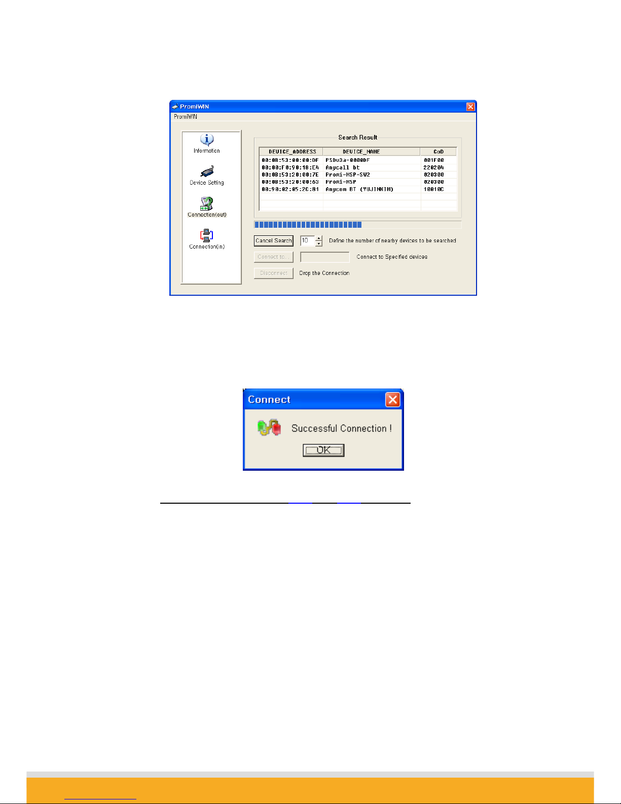
2-5. Select the ‘Connection(out)’ icon in the list control box and click the SEARCH
button.
Promi SD™ User Manual ver 1.7
www.initium.co.kr
18
2-6. Search SD01 from the searched list. Device Address of SD01 can be found on the
back side of SD01. If you find SD01, press Cancel button to finish searching.
Make sure that Status LED of SD01 is still blinking in Green color.
2-7. Please select SD01 from the searched list, then press CONNECT TO button.
2-8. You will get Successful Connection message.
2-9. Now, Status LEDs on Both SD01 and SD02 are Green, which means they are
connected.
2-10. Do not detach SD02 from your computer yet, we will go to next stage for Auto-
connection (Always-connection).

Promi SD™ User Manual ver 1.7
www.initium.co.kr
19
2.1.3 Let’s make Auto-Connection between SD01 and SD02.
3-1. With SD02 which is still attached to your computer, in Connection(out) page,
press DISCONNECT button at the bottom to release the connection for a while.
SD02 remembers who was the last-connected device, even after Disconnected.
3-2. Now, Status LEDs of SD02 becomes ‘Orange’, as well as SD01, as they are
disconnected.
3-3. Select Device Setting icon in the list control box, and select MODE1 in Operation
Mode and apply.

Promi SD™ User Manual ver 1.7
www.initium.co.kr
20
3-4. Now jobs for SD02 are finished. Detach SD02 from your computer.
3-5. Attach SD01 to your computer.
3-6. Restart Promi-WIN™.
3-7. Select Device Setting icon in the list control box, and select MODE2 in Operation
Mode and apply.
3-8. Now, detach SD01 from your computer.
3-9. Make sure that power to Both SD01 and SD02 are supplied.
With two of the SD01 and SD02, turn off both using Switch on the side of its body.
Then, turn on again Both SD01 and SD02 almost at the same time.
Now, you will see Green Status LEDs on both units.
SD01 and SD02 will be connected automatically, whenever, if configuration is not
changed.
This manual suits for next models
2
Table of contents


