Inmarsat Fleet One User manual

Fleet One
V. 1.2


Installation Manual
Fleet One


Installation Manual
Fleet One
V.1.2

© 2014 by Inmarsat Maritime
v.1.2
For assistance or additional information about
this Installation Manual, please contact
Inmarsat Maritime Customer Support at:
Tel: +44(0) 20 7728 1020
Email: [email protected]
Whilst the above information has been prepared by Inmarsat in good faith, and all
reasonable eorts have been made to ensure its accuracy, Inmarsat makes no warranty
or representation as to the accuracy, completeness or fitness for purpose or use of the
information. Inmarsat shall not be liable for any loss or damage of any kind, including
indirect or consequential loss, arising from use of the information and all warranties
and conditions, whether express or implied by statute, common law or otherwise, are
hereby excluded to the extent permitted by English law. INMARSAT is a trademark of the
International Mobile Satellite Organisation, the Inmarsat LOGO is a trademark of Inmarsat
(IP) Company Limited. Both trademarks are licensed to Inmarsat Global Limited.
© Inmarsat Global Limited 2014. All rights reserved. Inmarsat Fleet One 2014

v. 1.2
©INMARSAT MARITIME
V
Contents
Certifications ..........................................................................VII
Federal Communication Commission Notice...............................................................................VII
FCC Identifier: Q04-AVIFLONEINM...................................................................................................VII
Industry Canada Statement ..............................................................................................................VIII
EC Declaration of Conformity............................................................................................................VIII
Safety Instructions ..................................................................................................................................IX
System Configuration.............................................................................................................................XI
User Equipment Lists .............................................................................................................................XII
1 Fleet One User Equipment......................................................... 1
1.1 Introduction.................................................................................................................................. 1
1.2 Above Deck Unit.......................................................................................................................... 1
1.3 Below Deck Unit.......................................................................................................................... 2
1.4 Wired Primary Handset with Cradle..................................................................................... 2
2 Installation of the User Equipment ..................................3
2.1 Installation of ADU..................................................................................................................... 3
2.1.1 Overview .....................................................................................................................................3
2.1.2 Radiation Hazard ....................................................................................................................3
2.1.3 Interference.............................................................................................................................. 4
2.1.4 Obstruction ...............................................................................................................................5
2.1.5 Antenna Mast ......................................................................................................................... 6
2.1.6 Installing Antenna Unit ........................................................................................................ 8
2.2 Installation of BDU.....................................................................................................................9
2.3 Installation of Primary Handset............................................................................................11
3 Connections ..............................................................................12
3.1 BDU’s Outputs Connection....................................................................................................13
3.1.1 GPS Output Connector.......................................................................................................13
3.1.2 Grounding Stud......................................................................................................................13

Installation Manual - Fleet One
© INMARSAT MARITIME
VI
4 Getting Started On The System..............................................14
4.1 Installing the SIM card.............................................................................................................14
4.2 Powering up the terminal .......................................................................................................15
4.2.1 Switching on the BDU ..........................................................................................................15
4.3 Settings On Web Console ..................................................................................................... 16
4.3.1 Activating on Web Console ...............................................................................................16
4.3.2 Satellite Selection.................................................................................................................17
4.3.3 Data Connection Settings .................................................................................................18
4.3.4 GPS Settings......................................................................................................................... 20
4.3.5 Save Settings..........................................................................................................................21
5 Glossary.......................................................................... 22
APPENDIX A: Outline Drawings ............................................. 23
A-1 ADU Outline Dimensions .......................................................................................................23
A-2 ADU Hole Pattern (Cut-out Holes) .................................................................................. 24
A-3 BDU Outline Dimensions .......................................................................................................25
A-4 Primary Handset Outline Dimensions ............................................................................. 26

v. 1.2
©INMARSAT MARITIME
VII
Certifications
Federal Communication Commission Notice
FCC Identifier: Q04-AVIFLONEINM
USE CONDITIONS
This device complies with part 15 of the FCC Rules. Operation is subject to the follow-
ing two Conditions:
1. This device may not cause harmful interference, and
2. This device must accept any interference received, including interference that
may cause undesired operation.
NOTE
This equipment has been tested and found to comply with the limits for a Class B
digital device, pursuant to Part 15 of the FCC Rules. These limits are designed to pro-
vide reasonable protection against harmful interference in a residential installation.
This equipment generates, uses and can radiate radio frequency energy and, if not
installed and used in accordance with the instructions, may cause harmful interfer-
ence to radio communications. However, there is no guarantee that interference will
not occur in a particular installation.
If this equipment does cause harmful interference to radio or television reception,
which can be determined by turning the equipment o and on, the user is encouraged
to try to correct the interference by one of the following measures:
> Reorient or relocate the receiving antenna.
> Increase the separation between the equipment and receiver.
> Connect the equipment into an outlet on a circuit dierent from that to which
the receiver is connected.
> Consult the dealer or an experienced radio/TV technician for help.
IMPORTANT NOTE: EXPOSURE TO RADIO FREQUENCY RADIATION
This Device complies with FCC & IC radiation exposure limits set forth for an un-
controlled environment. The Antenna used for this transmitter must be installed to
provide a separation distance of at least 100cm from all persons and must not be
co-located or operating in conjunction with any other antenna or transmitter.
FCC CAUTION
Any Changes or modifications not expressly approved by the manufacturer could void
the user’s authority, which is granted by the FCC, to operate this Fleet One satellite
Communication System .

Installation Manual - Fleet One
© INMARSAT MARITIME
VIII
Industry Canada Statement
IC: 5023B-AVIFLONEINM
This device complies with Radio standard specification RSS-170 of Industry Canada
Rules. Operation is subject to the following two conditions:
1. This device may not cause harmful interference, and
2. This device must accept any interference received, including interference that
may cause undesired operation.
IMPORTANT NOTE: Radiation Exposure Statement
This equipment complies with IC radiation exposure limits set forth for an uncontrolled
environment. This antenna used for this transmitter must be installed to provide a
separation distance of at least 100cm from all persons and must not be co-located or
operating in conjunction with any other antenna or transmitter.
EC Declaration of Conformity
Fleet One Satellite communication system, to which this declaration relates, is in con-
formity with the following standards and/or other normative documents:
RoHS2 Directive 2011/65/EU
ETSI EN 301 444, ETSI EN 301 489-1, -19 & -20, IEC 60945 / EN 60945,
IEC 60950-1 AND EN 60950-1,
We hereby declare that all essential radio test suites have been carried out and that
the above named product is in conformity to all the essential requirements of Direc-
tive 1999/5/EC.
The Conformity Assessment procedure referred to Article 10 and detailed in Annex
[III] or [IV] of Directive 1999/5/EC has been followed with involvement of the following
notified body(ies):
TIMCO ENGINEERING Inc., P.O BOX 370, NEWBERRY, FLORIDA 32669.
Identification mark: 1177 (Notified Body number)
v. 1.2
©INMARSAT MARITIME
IX
Safety Instructions
For the sake of safety and protection, read the manual before attempting to use
the Fleet One User Equipment (UE).
The following general safety precautions must be observed during all phases
of operation, service and repair of this equipment. Failure to comply with these
precautions or with specific warnings elsewhere in this user guide violates safety
standards for the intended use of the UE.
Inmarsat assumes no liability for the customer’s failure to comply with these
requirements.
Hazard Symbols
Heated Surfaces Avoid touching those areas of the UE that are
being marked with this symbol otherwise it may
result in injury.
Antenna Radiation
Warning and Distance to
other Radiation Equipment
For safety reasons, all personnel must keep at
least 2 meters from the antenna.
Power Supply Turn o the power at the mains switchboard be-
fore beginning the installation.
Confirm the power voltage is compatible with
voltage rating of the equipment. It is highly
recommended to use a +24V DC power line, if it is
available on the vessel.
If there is no +24V DC power line provided by the
vessel, an external AC/DC power supply with an
input of 115/230V AC and an output of +24V DC
can be used.
Note: Be certain that the AC/DC power supply is
adequate to handle a high surge current of 25A at
24V DC for 1ms.

Installation Manual - Fleet One
© INMARSAT MARITIME
X
Equipment Ventilation
To ensure adequate cooling of the equipment, 5 centimeters of unobstructed
space must be maintained around all sides of the unit except the bottom side.
The operational temperature range of the transceiver is: -25°C to +55°C.
Fire Precautions
The equipment shall not be operated in the presence of flammable gases or
fumes as well as any explosive atmosphere. Operation of any electrical equip-
ment in such an environment constitutes a definite safety hazard.
Obtaining Licensing For Inmarsat Transceivers
Under rights given under ITU Radio Regulations, local telecommunications admin-
istrations establish and enforce national rules and regulations governing types of
emissions, power levels, and other parameters that aect the purity of signal, which
may be radiated in the various frequency bands of the radio spectrum.
To legally operate Inmarsat equipment, it is necessary to obtain permission from
the local telecommunications regulatory authorities of the country from which
you are operating. Using your equipment in any country without permission
causes you to run the risk of confiscation of the equipment by the local authori-
ties. The normal procedure to bring such equipment into another country is to
apply for a license before travel. If a license has not been obtained before travel,
the equipment may be put in to storage by local authorities until such time that a
license is obtained.
Grounding, cables
and connections
Service
The chassis of the equipment must be connected
to an electrical ground. This will minimise electric
shock and mutual interference. In short, the UE
must be grounded to the vessel.
Do not attempt to gain access to the interior of
the UE. Only qualified personnel authorized by its
manufacturer may perform service operations.
Failure to comply with this rule will result in the
warranty being void.
Under certain conditions, dangerous voltages may
exist even with the power cable removed. To avoid
injuries, always disconnect power before access-
ing the UE.

v. 1.2
©INMARSAT MARITIME
XI
System Configuration
Solid lines refers to the basic configuration.
FLEET ONE ADU
FLEET ONE BDU
Above Deck Unit
(To be installed in an exposed area)
Below Deck Unit
(To be installed in protected area)
+12V / 24V DC
AC/DC Power
Supply Unit
Primary Handset
GPS O/P (NEMA 0183)
Navigation
Equipment
Analog Telephone
RJ11
PC / Router
RJ45 (PoE)

Installation Manual - Fleet One
© INMARSAT MARITIME
XII
User Equipment Lists
Fleet One Optional Accessories
Description Order Code
Antenna Pole Mount with Mounting Kit SKP150/PM
Serial Port Cable for GPS O/P(1.8m) SKP150/SPC
Handset Extension Cable (5m) HS-EXT-5
Power Supply 240W AC/DC DIN Rail 24V
DC/10A SKP150/ADPS
Fleet One Standard Accessories
Description Order Code
Fleet One Primary Handset FL01-0PH00-01
Cable Pack (1.5m RJ45 & 1.8m RJ11) SB1/CABLEPK
Power Cable (1.8m) SKP150/DCPC
Handset Wall Mount Cradle SG5000/WMC
Fleet One Complete Standard Package
Description Order Code
Fleet One Terminal includes
>Fleet One Below Deck Unit (BDU)
>Fleet One Above Deck Unit (ADU)
>Fleet One Primary Handset
>Handset Wall Mount Cradle
>Antenna Coaxial Cable N to
TNC (10m)
>Power Cable (1.8m)
>Cable Pack (1.5m RJ45 & 1.8m RJ11)
>User Starter Kit for Fleet One
FL01-9TE00-01

v. 1.2
©INMARSAT MARITIME
1
1 Fleet One User Equipment
1.1 Introduction
The Fleet One UE consists of three units;
>Below Deck Unit (BDU) which is a communication unit
>Above Deck Unit (ADU) which is an antenna unit
>Wired Primary handset with cradle
1.2 Above Deck Unit
The ADU is a 3-axis controlled antenna unit which is self-tracking.
The radome covers the antenna unit, which is comprised of
>Antenna Module
>RF and GPS Module
>Rotary Joint
>Antenna Pedestal
The antenna module includes a low noise amplifier (LNA), high power amplifier
(HPA), and tracking receiver circuitry. All the signals and DC power pass through a
single coaxial antenna cable, which connects the ADU to the BDU.
Installation Manual - Fleet One
© INMARSAT MARITIME
2
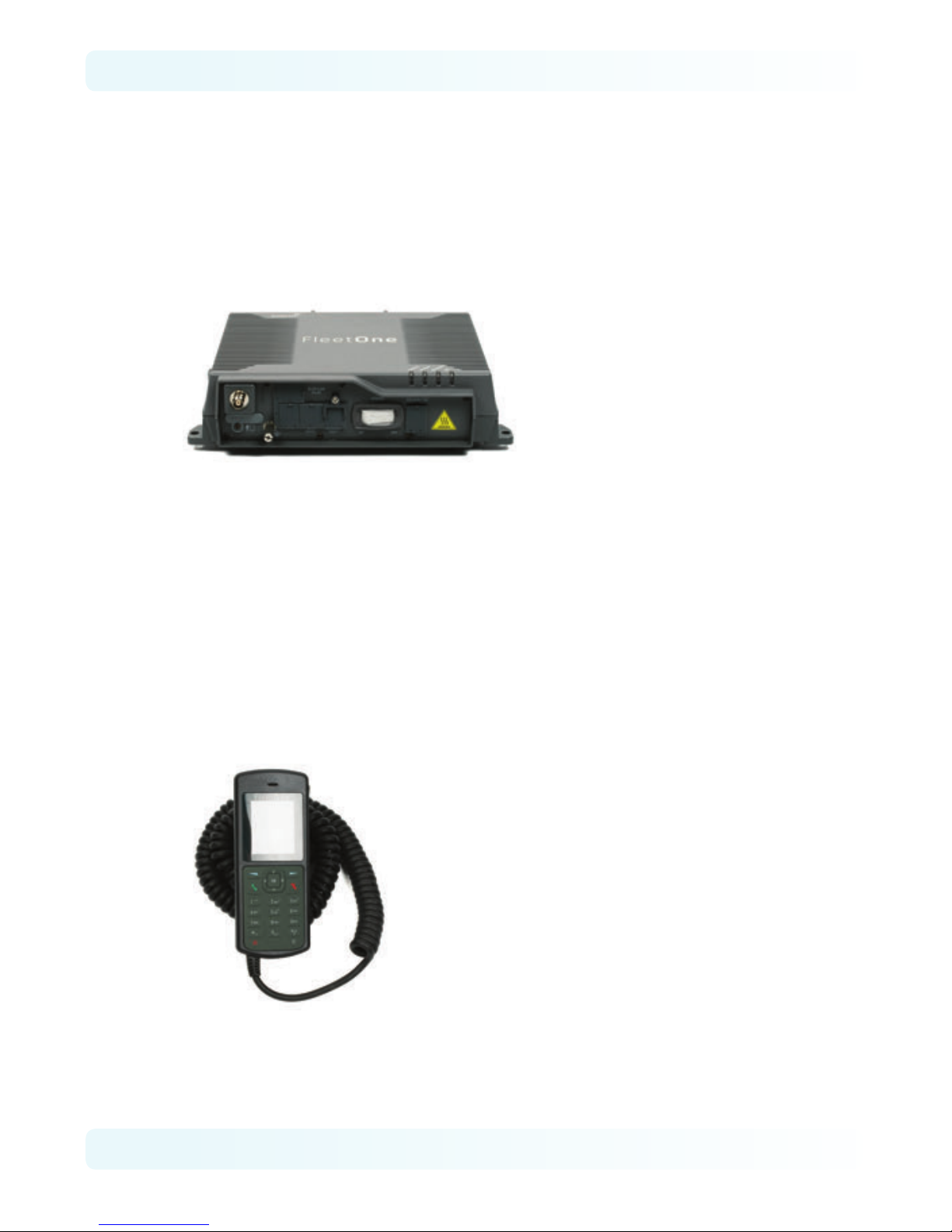
1.3 Below Deck Unit
The BDU is the heart unit of the Fleet One UE. It has several interface ports and
handles all communication links between the ADU, primary handset and the local
communication devices such as analog telephone, computer, network equip-
ment, navigation equipment etc.
The BDU is supplied by +12V or +24V DC power supply and it supplies power to the
ADU via a single RF / coaxial antenna cable.
1.4 Wired Primary Handset with Cradle
The wired Primary Handset has a colour liquid crystal display (LCD) and keypad
for making and receiving normal voice calls and sending SMS, similar to any mo-
bile phone. The handset is provided with a cradle.
Additionally, it can serve as a remote access device for user to access various
configuration parameters supported by the BDU.
The Primary Handset’s connector is plugged into the BDU’s primary handset port.
It is powered directly from the BDU.
v. 1.2
©INMARSAT MARITIME
3
2 Installation of the User Equipment
2.1 Installation of ADU
2.1.1 Overview
In general, any obstructing objects like a mast near the antenna unit can block
reception or transmission from the satellite’s line of sight. In addition, RF radiation
emitting from the antenna will aect the human body. When selecting a mount-
ing location, it is important to ensure that the antenna unit shall be free of severe
vibration and shock and heat and smoke from funnel. More guidelines will be
detailed in the next sections.
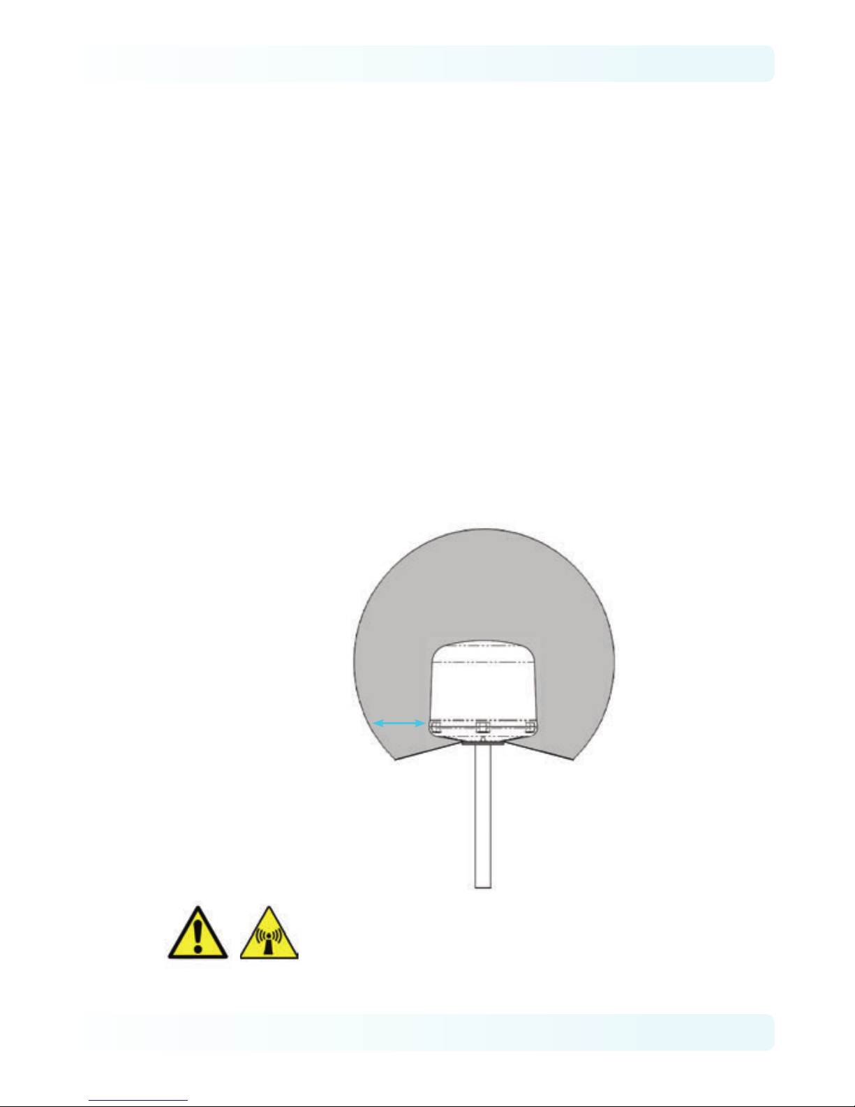
2.1.2 Radiation Hazard
Radio waves can pose a hazard to the human body. Safe distances are changed,
subjected to country guidelines and ship construction. There is no standard for-
mula to calculate the safe distance. The below guidelines are to be noted.
Fleet One ADU
Safety distance
1m
MICROWAVE RADIATION !
NO ADMITTANCE WITHIN
SAFETY DISTANCE
ANTENNA
UNIT
WARNING:
Keep away from the antenna radome at the mentioned safe
distance when it is transmitting. Microwave radiation can
be harmful to the human body, particularly the eyes.
Installation Manual - Fleet One
© INMARSAT MARITIME
4
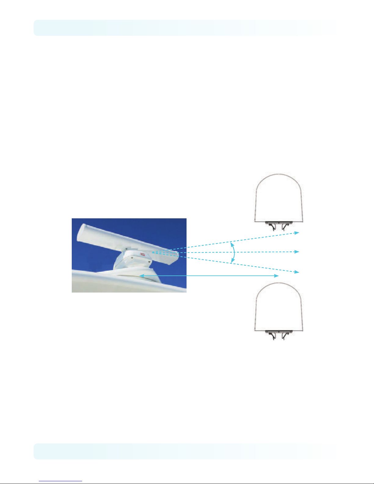
2.1.3 Interference
The antenna unit must be mounted as far as possible away from the ship’s radars,
MF/HF antennas, communication/navigation antennas, VSAT systems and any
high power radio transmitter (including other Inmarsat-based systems).
As for a ship’s radar (see below), it is dicult to provide the exact minimum
distance between a radar and the antenna unit due to dierent type of radars in
terms of power, radiation pattern and operating frequency band.
The antenna unit is recommended to be at least 5 meters away from the radar
position and at least ±15° from the radar’s vertical beam.
+15°
-15°
Antenna Unit
Antenna Unit
Minimum Radar Distance
5.0m
v. 1.2
©INMARSAT MARITIME
5
2.1.4 Obstruction
The mounting position of the antenna unit especially its line-of-sight are possibly
obstructed by any large obstacle on a vessel or ship. This will result in the degra-
dation of the satellite signal. It is very important to choose the ideal installation
site on the upper deck to minimise the satellite blocking.
Examples of the large obstacles are:
>Upper Deck and funnel of ship
>VSAT with its radome

Installation Manual - Fleet One
© INMARSAT MARITIME
6
>Large mechanical structure mounting of radars
With the understanding of the large obstacles, it helps in the decision of the
installation site with the reduction any of the physical obstructions.
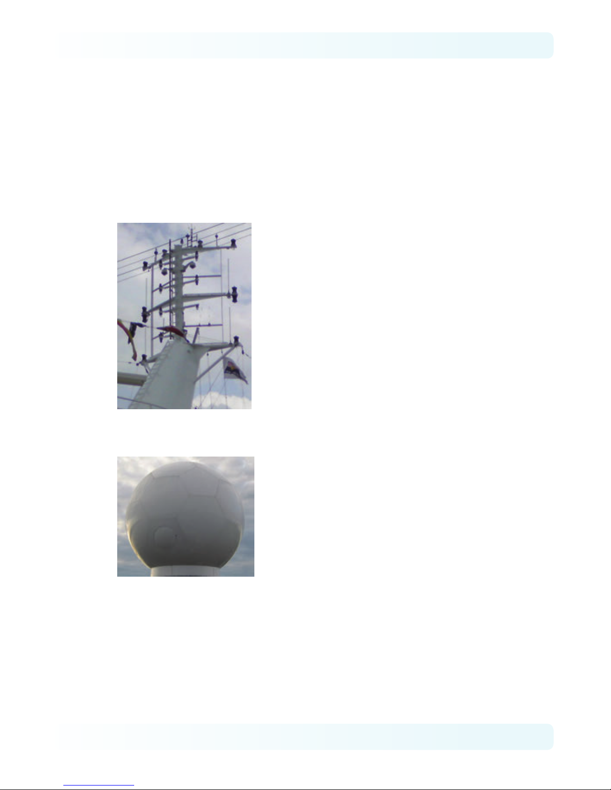
2.1.5 Antenna Mast
The antenna unit should be located at least 3-meters away from the ship’s mast
having a diameter of less than 15cm.
For Fleet One ADU, if the antenna mast is available on the vessel and it is free of
any shock or vibration, its physical size shall support the weight and size of that
Fleet One ADU. An example of the antenna mast is illustrated as below.
Other manuals for Fleet One
1
Table of contents


