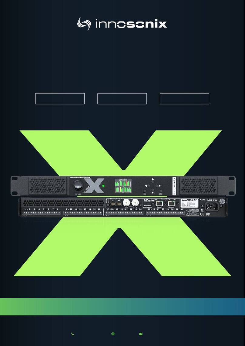
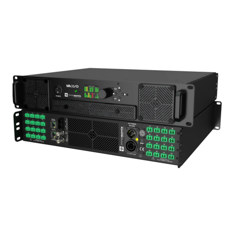
Innosonix MAXX Series User manual

MANUAL

INDEX
1. SAFETY INSTRUCTIONS . . . . . . . . . . . . . . . . . . . . . . . . . . . . . . . . . . . . . . . . . . . . . . . . . . . . . . Ê1
1.1. GENERAL . . . . . . . . . . . . . . . . . . . . . . . . . . . . . . . . . . . . . . . . . . . . . . . . . . . . . . . . . . . . . . Ê1
1.2. VENTILATION AND COOLING . . . . . . . . . . . . . . . . . . . . . . . . . . . . . . . . . . . . . . . . . . . . . Ê3
1.3. OPERATING CONDITIONS . . . . . . . . . . . . . . . . . . . . . . . . . . . . . . . . . . . . . . . . . . . . . . . . Ê4
2. TECHNICAL SPECIFICATION. . . . . . . . . . . . . . . . . . . . . . . . . . . . . . . . . . . . . . . . . . . . . . . . . . . Ê5
2.1. MAxx/HP² front view. . . . . . . . . . . . . . . . . . . . . . . . . . . . . . . . . . . . . . . . . . . . . . . . . . . . . Ê5
2.2. MAxx/HP² back view . . . . . . . . . . . . . . . . . . . . . . . . . . . . . . . . . . . . . . . . . . . . . . . . . . . . . Ê5
2.3. DIMENSIONS & WEIGHT . . . . . . . . . . . . . . . . . . . . . . . . . . . . . . . . . . . . . . . . . . . . . . . . . Ê7
2.4. CONNECTIONS & CABLE . . . . . . . . . . . . . . . . . . . . . . . . . . . . . . . . . . . . . . . . . . . . . . . . . Ê8
2.4.1. MAINS SUPPLY . . . . . . . . . . . . . . . . . . . . . . . . . . . . . . . . . . . . . . . . . . . . . . . . . . . . . . Ê8
2.4.2. AVAILABLE POWER CORDS. . . . . . . . . . . . . . . . . . . . . . . . . . . . . . . . . . . . . . . . . . . Ê10
2.4.3. ETHERNET / DANTE . . . . . . . . . . . . . . . . . . . . . . . . . . . . . . . . . . . . . . . . . . . . . . . . . Ê11
NETWORK MODES . . . . . . . . . . . . . . . . . . . . . . . . . . . . . . . . . . . . . . . . . . . . . . . . . . . . . Ê11
DANTE IP SETTINGS. . . . . . . . . . . . . . . . . . . . . . . . . . . . . . . . . . . . . . . . . . . . . . . . . . . . Ê13
CONTROL IP SETTINGS . . . . . . . . . . . . . . . . . . . . . . . . . . . . . . . . . . . . . . . . . . . . . . . . . Ê13
HOSTNAME. . . . . . . . . . . . . . . . . . . . . . . . . . . . . . . . . . . . . . . . . . . . . . . . . . . . . . . . . . . Ê13
NETWORK SERVICES . . . . . . . . . . . . . . . . . . . . . . . . . . . . . . . . . . . . . . . . . . . . . . . . . . . Ê13
2.4.4. MADI (AES10) / AES3 . . . . . . . . . . . . . . . . . . . . . . . . . . . . . . . . . . . . . . . . . . . . . . . . Ê14
MADI Optical. . . . . . . . . . . . . . . . . . . . . . . . . . . . . . . . . . . . . . . . . . . . . . . . . . . . . . . . . . Ê14
MADI Coaxial / AES3 . . . . . . . . . . . . . . . . . . . . . . . . . . . . . . . . . . . . . . . . . . . . . . . . . . . Ê14
2.5. AMP OUTPUT. . . . . . . . . . . . . . . . . . . . . . . . . . . . . . . . . . . . . . . . . . . . . . . . . . . . . . . . . . Ê15
2.5.1. Bridge Mode. . . . . . . . . . . . . . . . . . . . . . . . . . . . . . . . . . . . . . . . . . . . . . . . . . . . . . . Ê16
2.5.2. Overcurrent behaviour. . . . . . . . . . . . . . . . . . . . . . . . . . . . . . . . . . . . . . . . . . . . . . Ê16
2.6. POWER DISTRIBUTION. . . . . . . . . . . . . . . . . . . . . . . . . . . . . . . . . . . . . . . . . . . . . . . . . . Ê17
3. IDFM (FIRMWARE UPDATE AND IP CONTROL) . . . . . . . . . . . . . . . . . . . . . . . . . . . . . . . . . . Ê18
3.1. DISCOVERY. . . . . . . . . . . . . . . . . . . . . . . . . . . . . . . . . . . . . . . . . . . . . . . . . . . . . . . . . . . . Ê18
3.2. IP SETTINGS . . . . . . . . . . . . . . . . . . . . . . . . . . . . . . . . . . . . . . . . . . . . . . . . . . . . . . . . . . . Ê20
3.3. FIRMWARE STORAGE . . . . . . . . . . . . . . . . . . . . . . . . . . . . . . . . . . . . . . . . . . . . . . . . . . . Ê21
3.4. FIRMWARE UPDATE . . . . . . . . . . . . . . . . . . . . . . . . . . . . . . . . . . . . . . . . . . . . . . . . . . . . Ê22
4. DSP (internal) . . . . . . . . . . . . . . . . . . . . . . . . . . . . . . . . . . . . . . . . . . . . . . . . . . . . . . . . . . . . . Ê23
5. Frontpannel . . . . . . . . . . . . . . . . . . . . . . . . . . . . . . . . . . . . . . . . . . . . . . . . . . . . . . . . . . . . . . Ê24
5.1. DISPLAY / BUTTONS . . . . . . . . . . . . . . . . . . . . . . . . . . . . . . . . . . . . . . . . . . . . . . . . . . . . Ê24
5.1.1. DISPLAY MENU. . . . . . . . . . . . . . . . . . . . . . . . . . . . . . . . . . . . . . . . . . . . . . . . . . . . . Ê24
5.1.2. OVERVIEW. . . . . . . . . . . . . . . . . . . . . . . . . . . . . . . . . . . . . . . . . . . . . . . . . . . . . . . . . Ê25
5.1.3. DISPLAY DEVICE LOCK. . . . . . . . . . . . . . . . . . . . . . . . . . . . . . . . . . . . . . . . . . . . . . . Ê25
5.2. POWER LED . . . . . . . . . . . . . . . . . . . . . . . . . . . . . . . . . . . . . . . . . . . . . . . . . . . . . . . . . . . Ê26
6. WEBSITE. . . . . . . . . . . . . . . . . . . . . . . . . . . . . . . . . . . . . . . . . . . . . . . . . . . . . . . . . . . . . . . . . . Ê27
6.1. HEADER . . . . . . . . . . . . . . . . . . . . . . . . . . . . . . . . . . . . . . . . . . . . . . . . . . . . . . . . . . . . . . Ê27
6.1.1. PAGES . . . . . . . . . . . . . . . . . . . . . . . . . . . . . . . . . . . . . . . . . . . . . . . . . . . . . . . . . . . . Ê28

6.1.2. SAVE INTERNAL STORAGE . . . . . . . . . . . . . . . . . . . . . . . . . . . . . . . . . . . . . . . . . . . Ê28
6.1.3. PSU LIMIT . . . . . . . . . . . . . . . . . . . . . . . . . . . . . . . . . . . . . . . . . . . . . . . . . . . . . . . . . Ê28
6.1.4. AMP STATUS . . . . . . . . . . . . . . . . . . . . . . . . . . . . . . . . . . . . . . . . . . . . . . . . . . . . . . . Ê29
6.2. FOOTER . . . . . . . . . . . . . . . . . . . . . . . . . . . . . . . . . . . . . . . . . . . . . . . . . . . . . . . . . . . . . . Ê30
6.3. OVERVIEW . . . . . . . . . . . . . . . . . . . . . . . . . . . . . . . . . . . . . . . . . . . . . . . . . . . . . . . . . . . . Ê31
6.4. SELECTION AND GROUPING. . . . . . . . . . . . . . . . . . . . . . . . . . . . . . . . . . . . . . . . . . . . . Ê33
6.5. MODAL HEADER . . . . . . . . . . . . . . . . . . . . . . . . . . . . . . . . . . . . . . . . . . . . . . . . . . . . . . . Ê34
6.6. CHANNEL SETTINGS. . . . . . . . . . . . . . . . . . . . . . . . . . . . . . . . . . . . . . . . . . . . . . . . . . . . Ê35
6.6.1. NAME . . . . . . . . . . . . . . . . . . . . . . . . . . . . . . . . . . . . . . . . . . . . . . . . . . . . . . . . . . . . Ê35
6.6.2. BRIDGE MODE . . . . . . . . . . . . . . . . . . . . . . . . . . . . . . . . . . . . . . . . . . . . . . . . . . . . . Ê36
6.6.3. DC COUPLING . . . . . . . . . . . . . . . . . . . . . . . . . . . . . . . . . . . . . . . . . . . . . . . . . . . . . Ê37
6.6.4. POWER . . . . . . . . . . . . . . . . . . . . . . . . . . . . . . . . . . . . . . . . . . . . . . . . . . . . . . . . . . . Ê38
6.6.5. AUTO STANDBY . . . . . . . . . . . . . . . . . . . . . . . . . . . . . . . . . . . . . . . . . . . . . . . . . . . . Ê39
6.6.6. INPUT . . . . . . . . . . . . . . . . . . . . . . . . . . . . . . . . . . . . . . . . . . . . . . . . . . . . . . . . . . . . Ê41
6.6.7. MUTE. . . . . . . . . . . . . . . . . . . . . . . . . . . . . . . . . . . . . . . . . . . . . . . . . . . . . . . . . . . . . Ê43
6.6.8. CHANNEL VOLUME . . . . . . . . . . . . . . . . . . . . . . . . . . . . . . . . . . . . . . . . . . . . . . . . . Ê44
6.6.9. PHASE . . . . . . . . . . . . . . . . . . . . . . . . . . . . . . . . . . . . . . . . . . . . . . . . . . . . . . . . . . . . Ê45
6.6.10. DELAY . . . . . . . . . . . . . . . . . . . . . . . . . . . . . . . . . . . . . . . . . . . . . . . . . . . . . . . . . . . Ê46
6.6.11. PEQ . . . . . . . . . . . . . . . . . . . . . . . . . . . . . . . . . . . . . . . . . . . . . . . . . . . . . . . . . . . . . Ê47
PEQ Add / Remove. . . . . . . . . . . . . . . . . . . . . . . . . . . . . . . . . . . . . . . . . . . . . . . . . . . . . Ê48
ADVANCED EQ (FIR) . . . . . . . . . . . . . . . . . . . . . . . . . . . . . . . . . . . . . . . . . . . . . . . . . . . . Ê51
COPY TO / COPY FROM . . . . . . . . . . . . . . . . . . . . . . . . . . . . . . . . . . . . . . . . . . . . . . . . . Ê53
6.6.12. LIMIT . . . . . . . . . . . . . . . . . . . . . . . . . . . . . . . . . . . . . . . . . . . . . . . . . . . . . . . . . . . . Ê54
Look Ahead Delay . . . . . . . . . . . . . . . . . . . . . . . . . . . . . . . . . . . . . . . . . . . . . . . . . . . . . Ê55
Example Settings . . . . . . . . . . . . . . . . . . . . . . . . . . . . . . . . . . . . . . . . . . . . . . . . . . . . . . Ê55
6.6.13. SPEAKER SETTINGS . . . . . . . . . . . . . . . . . . . . . . . . . . . . . . . . . . . . . . . . . . . . . . . . Ê56
6.6.14. ANALYZER. . . . . . . . . . . . . . . . . . . . . . . . . . . . . . . . . . . . . . . . . . . . . . . . . . . . . . . . Ê60
MEASUREMENT . . . . . . . . . . . . . . . . . . . . . . . . . . . . . . . . . . . . . . . . . . . . . . . . . . . . . . . Ê61
6.7. INTERFACES . . . . . . . . . . . . . . . . . . . . . . . . . . . . . . . . . . . . . . . . . . . . . . . . . . . . . . . . . . . Ê64
6.7.1. INTERFACE STATUS . . . . . . . . . . . . . . . . . . . . . . . . . . . . . . . . . . . . . . . . . . . . . . . . . Ê64
6.7.2. INPUT . . . . . . . . . . . . . . . . . . . . . . . . . . . . . . . . . . . . . . . . . . . . . . . . . . . . . . . . . . . . Ê65
6.7.3. MADI FIBRE/DANTE OUTPUT . . . . . . . . . . . . . . . . . . . . . . . . . . . . . . . . . . . . . . . . . Ê66
6.8. DEVICE . . . . . . . . . . . . . . . . . . . . . . . . . . . . . . . . . . . . . . . . . . . . . . . . . . . . . . . . . . . . . . . Ê67
6.8.1. SETTINGS . . . . . . . . . . . . . . . . . . . . . . . . . . . . . . . . . . . . . . . . . . . . . . . . . . . . . . . . . Ê67
6.8.2. DANTE SETTINGS. . . . . . . . . . . . . . . . . . . . . . . . . . . . . . . . . . . . . . . . . . . . . . . . . . . Ê67
6.8.3. TIME. . . . . . . . . . . . . . . . . . . . . . . . . . . . . . . . . . . . . . . . . . . . . . . . . . . . . . . . . . . . . . Ê68
6.8.4. PSU . . . . . . . . . . . . . . . . . . . . . . . . . . . . . . . . . . . . . . . . . . . . . . . . . . . . . . . . . . . . . . Ê68
6.8.5. HOUSING . . . . . . . . . . . . . . . . . . . . . . . . . . . . . . . . . . . . . . . . . . . . . . . . . . . . . . . . . Ê69
6.8.6. VOLTAGE REFERENCE . . . . . . . . . . . . . . . . . . . . . . . . . . . . . . . . . . . . . . . . . . . . . . . Ê69
6.8.7. DEVICE MUTE . . . . . . . . . . . . . . . . . . . . . . . . . . . . . . . . . . . . . . . . . . . . . . . . . . . . . . Ê69
6.8.8. REMOTE MUTE. . . . . . . . . . . . . . . . . . . . . . . . . . . . . . . . . . . . . . . . . . . . . . . . . . . . . Ê70
6.8.9. DEVICE REBOOT. . . . . . . . . . . . . . . . . . . . . . . . . . . . . . . . . . . . . . . . . . . . . . . . . . . . Ê70

6.9. MUTEGROUPS. . . . . . . . . . . . . . . . . . . . . . . . . . . . . . . . . . . . . . . . . . . . . . . . . . . . . . . . . Ê71
6.10. PRESETS . . . . . . . . . . . . . . . . . . . . . . . . . . . . . . . . . . . . . . . . . . . . . . . . . . . . . . . . . . . . . Ê72
6.11. LOGGING . . . . . . . . . . . . . . . . . . . . . . . . . . . . . . . . . . . . . . . . . . . . . . . . . . . . . . . . . . . . Ê73
6.12. METERING . . . . . . . . . . . . . . . . . . . . . . . . . . . . . . . . . . . . . . . . . . . . . . . . . . . . . . . . . . . Ê74
7. ERROR CODES. . . . . . . . . . . . . . . . . . . . . . . . . . . . . . . . . . . . . . . . . . . . . . . . . . . . . . . . . . . . . Ê75
8. RESTful API . . . . . . . . . . . . . . . . . . . . . . . . . . . . . . . . . . . . . . . . . . . . . . . . . . . . . . . . . . . . . . . Ê77
8.1. GET DEVICE INFOMRATIONS. . . . . . . . . . . . . . . . . . . . . . . . . . . . . . . . . . . . . . . . . . . . . Ê78
8.2. SET CHANNEL MUTE. . . . . . . . . . . . . . . . . . . . . . . . . . . . . . . . . . . . . . . . . . . . . . . . . . . . Ê78
8.3. GET CHANNEL VOLUME OPTIONS . . . . . . . . . . . . . . . . . . . . . . . . . . . . . . . . . . . . . . . . Ê79
8.4. REMOVE PRESET WITH NAME TEST . . . . . . . . . . . . . . . . . . . . . . . . . . . . . . . . . . . . . . . Ê79
9. SERVICE . . . . . . . . . . . . . . . . . . . . . . . . . . . . . . . . . . . . . . . . . . . . . . . . . . . . . . . . . . . . . . . . . . Ê80
9.1. FUSES . . . . . . . . . . . . . . . . . . . . . . . . . . . . . . . . . . . . . . . . . . . . . . . . . . . . . . . . . . . . . . . . Ê80
9.2. FIRMWARE UPDATE . . . . . . . . . . . . . . . . . . . . . . . . . . . . . . . . . . . . . . . . . . . . . . . . . . . . Ê80
9.3. FILTER CLEANING . . . . . . . . . . . . . . . . . . . . . . . . . . . . . . . . . . . . . . . . . . . . . . . . . . . . . . Ê80
9.4. SPARE PARTS . . . . . . . . . . . . . . . . . . . . . . . . . . . . . . . . . . . . . . . . . . . . . . . . . . . . . . . . . . Ê81
10. DISPOSING . . . . . . . . . . . . . . . . . . . . . . . . . . . . . . . . . . . . . . . . . . . . . . . . . . . . . . . . . . . . . . Ê83
11. EU Declaration of Conformity . . . . . . . . . . . . . . . . . . . . . . . . . . . . . . . . . . . . . . . . . . . . . . Ê84
11.1. EN 55032:2012 . . . . . . . . . . . . . . . . . . . . . . . . . . . . . . . . . . . . . . . . . . . . . . . . . . . . . . . Ê84
11.2. EN 55103-2 . . . . . . . . . . . . . . . . . . . . . . . . . . . . . . . . . . . . . . . . . . . . . . . . . . . . . . . . . . Ê84
11.3. EN 62368-1:2014/AC:2015. . . . . . . . . . . . . . . . . . . . . . . . . . . . . . . . . . . . . . . . . . . . . . Ê85
11.4. MANUFACTURER. . . . . . . . . . . . . . . . . . . . . . . . . . . . . . . . . . . . . . . . . . . . . . . . . . . . . . Ê85
12. FCC Declaration of Conformity . . . . . . . . . . . . . . . . . . . . . . . . . . . . . . . . . . . . . . . . . . . . . Ê86

Chapter 1. SAFETY INSTRUCTIONS
1.1. GENERAL
Before using the product, please read this manual and follow all Safety Instructions.
They are used to protect you, help to avoid equipment defects and damages resulting
from improper use. Keep this manual in a safe place.
CAUTION: THE POWER SUPPLY CORD IS USED AS THE MAIN DISCONNECT
DEVICE, ENSURE THAT THE SOCKET-OUTLET IS LOCATED/INSTALLED NEAR
THE EQUIPMENT AND IS EASILY ACCESSIBLE
ATTENTION: LE CORDON DÕALIMENTATION EST UTILISƒ COMME
INTERRUPTEUR PRINCIPAL. LA PRISE DE COURANT DOIT æTRE SITUƒE OU
INSTALLƒE Ë PROXIMITƒ DE LÕƒQUIPEMENT ET æTRE FACILE DÕACCƒS
CAUTION - DANGER OF EXPLOSION IF BATTERY IS INCORRECTLY
REPLACED. REPLACE ONLY WITH THE SAME OR EQUIVALENT TYPE.
ATTENTION - DANGER DÕEXPLOSION LORSQUE LA BATTERIE NÕEST PAS
REMPLACƒE CORRECTEMENT. REMPLACER UNIQUEMENT AVEC DES
BATTERIES IDENTIQUES OU DÕUN TYPE ƒQUIVALENT
CAUTION - THESE SERVICING INSTRUCTIONS ARE FOR USE BY QUALIFIED
SERVICE PERSONNEL ONLY. TO REDUCE THE RISK OF ELECTRIC SHOCK DO
NOT PERFORM ANY SERVICING OTHER THAN THAT CONTAINED IN THE
OPERATING INSTRUCTIONS UNLESS YOU ARE QUALIFIED TO DO SO.
ATTENTION - CES CONSIGNES DÕENTRETIEN DOIVENT ETRE UNIQUEMENT
EMPLOYES PAR LE PERSONNEL DE SERVICE QUALIFIƒ. POUR RƒDUIRE LE
RISQUE DE CHOC ƒLECTRIQUE NE PAS EFFECTUER DES REPARATIONS
AUTRES QUE CEUX CONTENUS DANS LES INSTRUCTIONS DÕUTILISATION A
MOINS QUE VOUS SOYEZ QUALIFIE POUR LE FAIRE
The amplifier is a device of protection class 1. Make sure that the
protective conductor (earth) is connected properly. A missing earth can
lead to dangerous voltages at the enclousure!
MAXX/HP²
Chapter 1. SAFETY INSTRUCTIONS
1.1. GENERAL
2023-01-05 | Rev. 3.17.0 1.1. GENERAL | 1/86

Keep the device away from dust, moisture, water and other liquids! In such
case, the further usage is prohibited!
The amplifier has a relatively high output power and possibly can be a
hazard for people and speakers. Pay particular attention to any defective
set volume.
Do not touch the housing of the device, during operation. The surfaces can
be hot. After switching off the device, wait 30 minutes till touching the
device.
In the following cases it is necessary to return the amplifier for
examination to the manufacturer. Contact details can be found on our
website: www.innosonix.de
¥The unit has been dropped, mechanically damaged or treated
improperly.
¥The power cord or plug has been damaged.
¥Objects have fallen into the unit.
¥Liquid has been spilled into the unit.
¥The unit is not operating normally.
¥The device displays errors.
MAXX/HP²
Chapter 1. SAFETY INSTRUCTIONS
1.1. GENERAL
2023-01-05 | Rev. 3.17.0 1.1. GENERAL | 2/86

1.2. VENTILATION AND COOLING
Built-in and 19-inch racks must be ventilated adequately.
The active cooling system inside the device creates front to back ventilation.
Figure 1. MAXX/HP² Ventilation
MAXX/HP²
Chapter 1. SAFETY INSTRUCTIONS
1.2. VENTILATION AND COOLING
2023-01-05 | Rev. 3.17.0 1.2. VENTILATION AND COOLING | 3/86

1.3. OPERATING CONDITIONS
Enviromental
operating
temperature
0 - 40¡C
Thermal dissipation Fan, variable speed, temperature controlled front to rear airflow
32 CH
@230V @110V
amps power off 31 kcal/h 123 BTU/h 31 kcal/h 123 BTU/h
idle 84 kcal/h 333 BTU/h 88 kcal/h 349 BTU/h
1/8 power @ 4 Ohm 269 kcal/h 1066 BTU/h 270 kcal/h 1071 BTU/h
24 CH
@230V @110V
amps power off 31 kcal/h 123 BTU/h 31 kcal/h 123 BTU/h
idle 71 kcal/h 282 BTU/h 72 kcal/h 286 BTU/h
1/8 power @ 4 Ohm 210 kcal/h 833 BTU/h 212 kcal/h 840 BTU/h
MAXX/HP²
Chapter 1. SAFETY INSTRUCTIONS
1.3. OPERATING CONDITIONS
2023-01-05 | Rev. 3.17.0 1.3. OPERATING CONDITIONS | 4/86

Chapter 2. TECHNICAL SPECIFICATION
2.1. MAxx/HP² front view
Figure 2. MA32/HP² front view
Table 1. DEVICE ELEMENTS FRONT
NR DESRIPTION NOTE
POWER SWITCH Hard disconnect Mains
POWER LED POWER LED
DISPLAY DISPLAY / BUTTONS
BUTTONS DISPLAY / BUTTONS
VENTILATION GRILLS Magnetically attached see: SERVICE
2.2. MAxx/HP² back view
MAXX/HP²
Chapter 2. TECHNICAL SPECIFICATION
2.1. MAxx/HP² front view
2023-01-05 | Rev. 3.17.0 2.1. MAxx/HP² front view | 5/86

Figure 3. MA32/HP² back view
Figure 4. MA24/HP² back view
Table 2. DEVICE ELEMENTS BACK
NR DESRIPTION NOTE
MAINS SUPPLY MAINS SUPPLY
MADI MADI (AES10) / AES3
ETHERNET/DANTE ETHERNET / DANTE
AMP OUTPUTS AMP OUTPUT
MAXX/HP²
Chapter 2. TECHNICAL SPECIFICATION
2.2. MAxx/HP² back view
2023-01-05 | Rev. 3.17.0 2.2. MAxx/HP² back view | 6/86

2.3. DIMENSIONS & WEIGHT
Figure 5. MAXX/HP² dimensions
Dimensions W 482.60mm (19") H132.55mm (3 RU), D 389.29mm
32CH 24CH
Weight 19.6 kg 18.3 kg
MAXX/HP²
Chapter 2. TECHNICAL SPECIFICATION
2.3. DIMENSIONS & WEIGHT
2023-01-05 | Rev. 3.17.0 2.3. DIMENSIONS & WEIGHT | 7/86

2.4. CONNECTIONS & CABLE
Control input connectors RJ45 ( 100Mbit/s Ethernet )
Audio signal input connectors RJ45 ( DANTE ), BNC 75R ( MADI Coax, AES3id ), SC Optic ( MADI Fibre )
Speaker connector Wuerth Elektronik 691352710002
Phoenix Contact MSTB 2,5/ 2-ST - 1754449
AC mains C19
2.4.1. MAINS SUPPLY
Power supply Two Universal, regulated switch mode with PFC (Power Factor Correction)
Operating Voltage 90 - 264VAC 50/60Hz
AC Current typ. 14.3A per PSU
Inrush Current 60A max.
Suggested circuit
breaker
2x B16
Earth Leakage
Current
<0.75mA / 240V
32 CH Version
Power Factor @230V @110V
amps power off 0.46 0.85
idle 0.64 0.95
1/8 power @ 4 Ohm 0.96 0.98
Consumption /
current draw
@230V @110V
amps power off 36W 36W
idle 98W 102W
1/8 power @ 4 Ohm 1514W 1532W
24 CH Version
Power Factor @230V @110V
amps power off 0.44 0.83
idle 0.58 0.93
1/8 power @ 4 Ohm 0.94 0.99
Consumption /
current draw
@230V @110V
MAXX/HP²
Chapter 2. TECHNICAL SPECIFICATION
2.4. CONNECTIONS & CABLE
2023-01-05 | Rev. 3.17.0 2.4. CONNECTIONS & CABLE | 8/86

amps power off 36W 36W
idle 83W 84W
1/8 power @ 4 Ohm 1145W 1150W
The devices contains an internal fuse see: FUSES
The Amplifier comes with a power cord according to the planned place of use.
There are two separate power supplies in the amplifier. They can be used individually or
together to increase power output. If only half power is needed, they can be seen as
completely redundant.
MAXX/HP²
Chapter 2. TECHNICAL SPECIFICATION
2.4. CONNECTIONS & CABLE
2023-01-05 | Rev. 3.17.0 2.4. CONNECTIONS & CABLE | 9/86

2.4.2. AVAILABLE POWER CORDS
NR DESRIPTION
3-pin Schuko CEE 7/7
3-pin GB BS 1363A
IEC-LOCK C19
To release the cable from the amplifier, the red Button has to be pulled to the back.
MAXX/HP²
Chapter 2. TECHNICAL SPECIFICATION
2.4. CONNECTIONS & CABLE
2023-01-05 | Rev. 3.17.0 2.4. CONNECTIONS & CABLE | 10/86

2.4.3. ETHERNET / DANTE
There are two differnet network devices inside the amplifier, the Control Module and
the Module. There are three different network modes that determine which
device can be reached at which network port.
Do not connect both Port to the same Switch if no different VLANs are
configured.
NETWORK MODES
Figure 6. NETWORK MODES
MAXX/HP²
Chapter 2. TECHNICAL SPECIFICATION
2.4. CONNECTIONS & CABLE
2023-01-05 | Rev. 3.17.0 2.4. CONNECTIONS & CABLE | 11/86

To change the network modes, use the DEVICE page DANTE SETTINGS.
Alternatively, the Dante Contoller Software can be used. (DOWNLOAD HERE)
Open the Dante Controller and go to Device View:
Figure 7. Dante Controller
The Device View Popup appears:
Figure 8. Dante Device View
Select the device in the Dropdown and change to tab Network Config . The
currently selected network mode appears in the Switch Configuration box. By selecting
the new Mode , a Popup opens that asked, whether youÕre really sure to do that. After
clicking YES, the Brooklyn Module inside the Amplifier restart, so it can take a few
MAXX/HP²
Chapter 2. TECHNICAL SPECIFICATION
2.4. CONNECTIONS & CABLE
2023-01-05 | Rev. 3.17.0 2.4. CONNECTIONS & CABLE | 12/86

seconds till the Dante Device is back online.
DANTE IP SETTINGS
To control and change IP Settings of DANTE, use the DEVICE page DANTE SETTINGS, or
use in Dante Device View.
CONTROL IP SETTINGS
There are several ways to change the IP of an Amplifier. See DISPLAY MENU to change
on Display Menu, DEVICE to change on Website or use the external software IDFM (see
IP SETTINGS).
There are three different IP Types available:
Table 3. IP TYPES
TYPE DESCRIPTION
static set IP, SUBNET and GATEWAY manually
dhcp system tries to get a DHCP release, there is also an auto ip fallback, if no lease available
auto-ip force zeroconf IP, device will get an address with a 169.254/16 prefix (that is, 169.254.xxx.xxx)
HOSTNAME
With mDNS the device is also available with its hostname. With hostname AMP1 the
local name is AMP1.local. The Name can be used to call every network service, like a
webbrowser, http://AMP1.local.
There are several ways to change the Hostname of an Amplifier. See DEVICE to change
on Website or use the external software IDFM.
NETWORK SERVICES
¥Full remote control via the website hosted on the device (see WEBSITE)
¥REST-API, JSON based web service for integration in media control systems (see
RESTful API)
¥mDNS name resolution and servicediscovery (INFO HERE)
¥syslog integration to send notifications to external syslog server (INFO HERE)
MAXX/HP²
Chapter 2. TECHNICAL SPECIFICATION
2.4. CONNECTIONS & CABLE
2023-01-05 | Rev. 3.17.0 2.4. CONNECTIONS & CABLE | 13/86

2.4.4. MADI (AES10) / AES3
MADI (Multichannel Audio Digital Interface) or AES10 is a standard that defines
electrical characteristics and the data format of an interface that carries multiple
channels of digital audio. There are two Coaxial Inputs available, which also can be used
as AES3 Inputs, one optical input and an optical output. On every Input the device
supports 44.1kHz / 48kHz with 56 / 64 channels and 88.2 kHz / 96kHz with 28 / 32
channels.
MADI Optical
To use the Optical MADI interface, a 1300nm multimode cable with SC connectors is
required.
MADI Coaxial / AES3
The two BNC (75 Ohm) jacks are multifunctional inputs and can be used as AES10 MADI
or AES3 interface.
To use the BNC input for AES3, a 110 to 75 Ohm impedance transformer like
(NADITBNC-F) or (NADITBNC-FX) is required.
Every AES3 input has an asynchronous samplerate converter enabled which can hanlde
samplerates from 32kHz - 192kHz.
MAXX/HP²
Chapter 2. TECHNICAL SPECIFICATION
2.4. CONNECTIONS & CABLE
2023-01-05 | Rev. 3.17.0 2.4. CONNECTIONS & CABLE | 14/86

2.5. AMP OUTPUT
To connect speakers, use 2-Pol Terminal Blocks.
Output Power (EIAJ Test
Standard 1kHz 1% THD)
4½ 8½ 8½ Bridge-Mode
280W 140W 500W
Max output Voltage 52 Vpeak 104 Vpeak
Max output Current Limited 20 Apeak
Emergency Shutdown Current 31 Apeak
DC Offset <25mV
Frequency response 10Hz-20kHz / 4-8½: +0.5 -0.5dB
S/N typ 105dBA
Analog Gain Software Adjustable, 0dBFS on any Input Interface ⇒20Vp- 60Vp(default: 60Vp)
THD+N @ 4½ 1W 10W 280W 300W
< 0.05% < 0.05% 1% 2%
SMPTE IMD < 0.1% @ 1/8 Power 4½
CCIF IMD < 0.1% @ 1/8 Power 4½
Output impedance typ 10 m½
Crosstalk channel enabled channel disabled
typ < 75dB typ 90dB (distant
channels)
typ < 100dB
Latency @48kHz 1.1ms
Protection Overtemperature, DC and Overcurrent
MAXX/HP²
Chapter 2. TECHNICAL SPECIFICATION
2.5. AMP OUTPUT
2023-01-05 | Rev. 3.17.0 2.5. AMP OUTPUT | 15/86

2.5.1. Bridge Mode
In bridge mode, only adjacent channels can be used together, like 1/2, 3/4, 5/6, É 31/32.
The +Pin of both channels has to be connected to the speaker, the -stays unused in
this mode.
CH1 + ⇒"speaker +"
CH2 + ⇒"speaker -"
Speaker Wiring in Bridge Mode
2.5.2. Overcurrent behaviour
1. The integrated software CURRENT Limiter (LIMIT) will always try to limit the output
current to itÕs Max output Current Limited as specified in the datasheet. This will also
protect the amplifier output stage when a hard short between the output terminals
is present. The amp will drive ~0V and its maximum current specified.
2. If the software limiting will fail, an additional hardware comparator will shut down
the amplifier output stage if Emergency Shutdown Current is exceeded. The channel
has to be manually power cycled to recover from that state.
MAXX/HP²
Chapter 2. TECHNICAL SPECIFICATION
2.5. AMP OUTPUT
2023-01-05 | Rev. 3.17.0 2.5. AMP OUTPUT | 16/86
Other manuals for MAXX Series
1
This manual suits for next models
2
Table of contents
Other Innosonix Amplifier manuals
Popular Amplifier manuals by other brands

Sound Devices
Sound Devices MM-1 User guide and technical information

Crown
Crown ce 4000 Operation manual
Dual
Dual XPA2100 Installation & owner's manual
Toner
Toner TPA-20U user manual
BFI Automation
BFI Automation 3001S Original operating instructions
R.V.R. Elettronica
R.V.R. Elettronica PJ500M-C user manual
