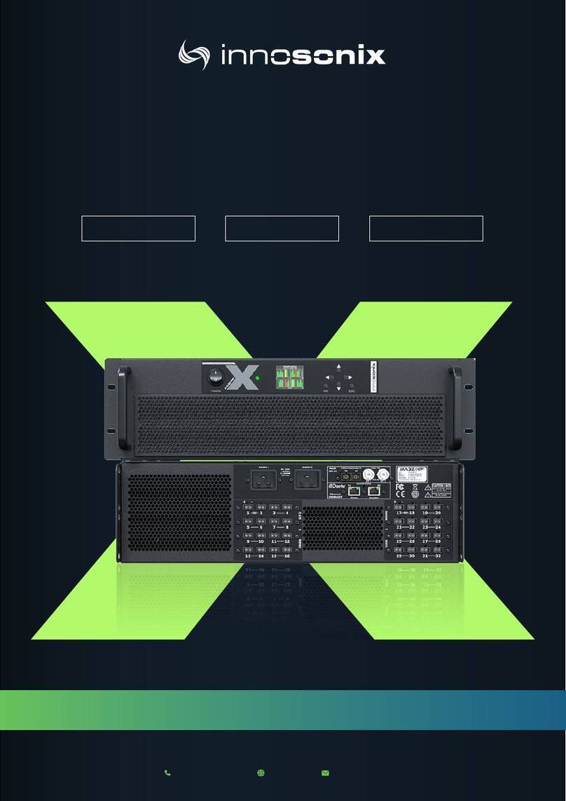
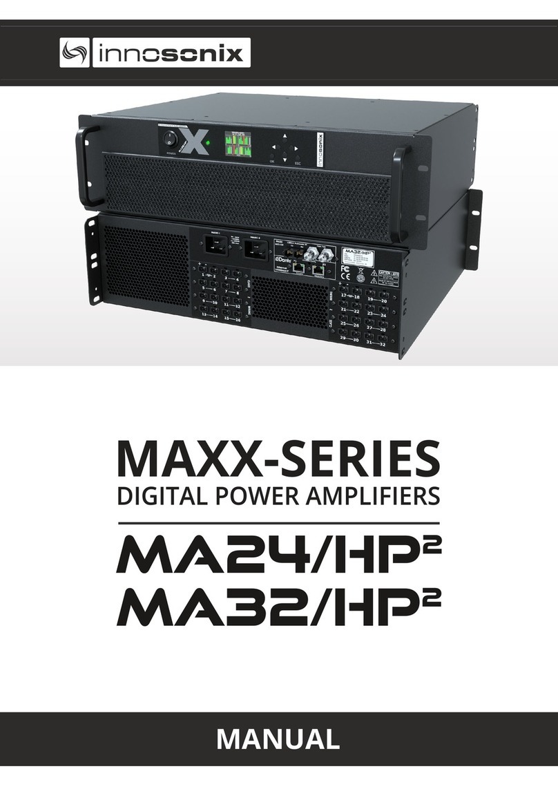
Innosonix MAXX Series User manual


INDEX
1. SAFETY INSTRUCTIONS . . . . . . . . . . . . . . . . . . . . . . . . . . . . . . . . . . . . . . . . . . . . . . . . . . . . . . Ê1
1.1. INSTALLATION INSTRUCTIONS . . . . . . . . . . . . . . . . . . . . . . . . . . . . . . . . . . . . . . . . . . . . Ê3
1.2. VENTILATION AND COOLING . . . . . . . . . . . . . . . . . . . . . . . . . . . . . . . . . . . . . . . . . . . . . Ê3
2. HARDWARE . . . . . . . . . . . . . . . . . . . . . . . . . . . . . . . . . . . . . . . . . . . . . . . . . . . . . . . . . . . . . . . . Ê4
2.1. CONTROLS . . . . . . . . . . . . . . . . . . . . . . . . . . . . . . . . . . . . . . . . . . . . . . . . . . . . . . . . . . . . . Ê4
2.2. ETHERNET . . . . . . . . . . . . . . . . . . . . . . . . . . . . . . . . . . . . . . . . . . . . . . . . . . . . . . . . . . . . . Ê5
2.3. AMPLIFIER . . . . . . . . . . . . . . . . . . . . . . . . . . . . . . . . . . . . . . . . . . . . . . . . . . . . . . . . . . . . . Ê5
2.3.1. VOLTAGE, CURRENT AND POWER . . . . . . . . . . . . . . . . . . . . . . . . . . . . . . . . . . . . . . Ê5
2.4. GAIN . . . . . . . . . . . . . . . . . . . . . . . . . . . . . . . . . . . . . . . . . . . . . . . . . . . . . . . . . . . . . . . . . . Ê6
2.5. PROTECTION CIRCUITS . . . . . . . . . . . . . . . . . . . . . . . . . . . . . . . . . . . . . . . . . . . . . . . . . . Ê6
2.5.1. AMP CHIP / CHANNEL MAPPING. . . . . . . . . . . . . . . . . . . . . . . . . . . . . . . . . . . . . . . Ê7
2.6. SPEAKER CONNECTION . . . . . . . . . . . . . . . . . . . . . . . . . . . . . . . . . . . . . . . . . . . . . . . . . . Ê8
3. HEAT GENERATION AND DISSIPATION . . . . . . . . . . . . . . . . . . . . . . . . . . . . . . . . . . . . . . . . . Ê9
4. SOFTWARE. . . . . . . . . . . . . . . . . . . . . . . . . . . . . . . . . . . . . . . . . . . . . . . . . . . . . . . . . . . . . . . . Ê10
4.1. IDFM (FIRMWARE UPDATE AND IP CONTROL) . . . . . . . . . . . . . . . . . . . . . . . . . . . . . . Ê10
4.1.1. DISCOVERY . . . . . . . . . . . . . . . . . . . . . . . . . . . . . . . . . . . . . . . . . . . . . . . . . . . . . . . . Ê11
4.1.2. IP SETTINGS . . . . . . . . . . . . . . . . . . . . . . . . . . . . . . . . . . . . . . . . . . . . . . . . . . . . . . . Ê12
4.1.3. FIRMWARE STORAGE. . . . . . . . . . . . . . . . . . . . . . . . . . . . . . . . . . . . . . . . . . . . . . . . Ê13
4.1.4. FIRMWARE UPDATE . . . . . . . . . . . . . . . . . . . . . . . . . . . . . . . . . . . . . . . . . . . . . . . . . Ê14
4.2. DSP (internal). . . . . . . . . . . . . . . . . . . . . . . . . . . . . . . . . . . . . . . . . . . . . . . . . . . . . . . . . . Ê15
4.3. USER INTERFACES. . . . . . . . . . . . . . . . . . . . . . . . . . . . . . . . . . . . . . . . . . . . . . . . . . . . . . Ê16
4.3.1. DISPLAY / BUTTONS . . . . . . . . . . . . . . . . . . . . . . . . . . . . . . . . . . . . . . . . . . . . . . . . Ê16
DISPLAY MENU . . . . . . . . . . . . . . . . . . . . . . . . . . . . . . . . . . . . . . . . . . . . . . . . . . . . . . . . Ê17
OVERVIEW . . . . . . . . . . . . . . . . . . . . . . . . . . . . . . . . . . . . . . . . . . . . . . . . . . . . . . . . . . . . Ê18
DISPLAY DEVICE LOCK. . . . . . . . . . . . . . . . . . . . . . . . . . . . . . . . . . . . . . . . . . . . . . . . . . Ê18
4.3.2. POWER LED . . . . . . . . . . . . . . . . . . . . . . . . . . . . . . . . . . . . . . . . . . . . . . . . . . . . . . . Ê19
4.3.3. WEBSITE . . . . . . . . . . . . . . . . . . . . . . . . . . . . . . . . . . . . . . . . . . . . . . . . . . . . . . . . . . Ê20
HEADER . . . . . . . . . . . . . . . . . . . . . . . . . . . . . . . . . . . . . . . . . . . . . . . . . . . . . . . . . . . . . . Ê20
PAGES . . . . . . . . . . . . . . . . . . . . . . . . . . . . . . . . . . . . . . . . . . . . . . . . . . . . . . . . . . . . . . . Ê21
SAVE INTERNAL STORAGE. . . . . . . . . . . . . . . . . . . . . . . . . . . . . . . . . . . . . . . . . . . . . . . Ê21
PSU LIMIT . . . . . . . . . . . . . . . . . . . . . . . . . . . . . . . . . . . . . . . . . . . . . . . . . . . . . . . . . . . . Ê21
AMP STATUS . . . . . . . . . . . . . . . . . . . . . . . . . . . . . . . . . . . . . . . . . . . . . . . . . . . . . . . . . . Ê22
FOOTER . . . . . . . . . . . . . . . . . . . . . . . . . . . . . . . . . . . . . . . . . . . . . . . . . . . . . . . . . . . . . . Ê23
OVERVIEW . . . . . . . . . . . . . . . . . . . . . . . . . . . . . . . . . . . . . . . . . . . . . . . . . . . . . . . . . . . . Ê24
INTERFACES . . . . . . . . . . . . . . . . . . . . . . . . . . . . . . . . . . . . . . . . . . . . . . . . . . . . . . . . . . Ê44
DEVICE. . . . . . . . . . . . . . . . . . . . . . . . . . . . . . . . . . . . . . . . . . . . . . . . . . . . . . . . . . . . . . . Ê46
MUTEGROUPS . . . . . . . . . . . . . . . . . . . . . . . . . . . . . . . . . . . . . . . . . . . . . . . . . . . . . . . . Ê48
PRESETS. . . . . . . . . . . . . . . . . . . . . . . . . . . . . . . . . . . . . . . . . . . . . . . . . . . . . . . . . . . . . . Ê49
LOGGING. . . . . . . . . . . . . . . . . . . . . . . . . . . . . . . . . . . . . . . . . . . . . . . . . . . . . . . . . . . . . Ê50

METERING. . . . . . . . . . . . . . . . . . . . . . . . . . . . . . . . . . . . . . . . . . . . . . . . . . . . . . . . . . . . Ê51
4.3.4. ERROR CODES . . . . . . . . . . . . . . . . . . . . . . . . . . . . . . . . . . . . . . . . . . . . . . . . . . . . . Ê52
4.3.5. RESTful API . . . . . . . . . . . . . . . . . . . . . . . . . . . . . . . . . . . . . . . . . . . . . . . . . . . . . . . . Ê54
GET DEVICE INFOMRATIONS . . . . . . . . . . . . . . . . . . . . . . . . . . . . . . . . . . . . . . . . . . . . Ê55
SET CHANNEL MUTE . . . . . . . . . . . . . . . . . . . . . . . . . . . . . . . . . . . . . . . . . . . . . . . . . . . Ê55
GET CHANNEL VOLUME OPTIONS. . . . . . . . . . . . . . . . . . . . . . . . . . . . . . . . . . . . . . . . Ê56
REMOVE PRESET WITH NAME TEST. . . . . . . . . . . . . . . . . . . . . . . . . . . . . . . . . . . . . . . Ê56
5. DIMENSIONS AND WEIGHT . . . . . . . . . . . . . . . . . . . . . . . . . . . . . . . . . . . . . . . . . . . . . . . . . Ê57
5.1. DIMENSIONS . . . . . . . . . . . . . . . . . . . . . . . . . . . . . . . . . . . . . . . . . . . . . . . . . . . . . . . . . . Ê57
5.2. WEIGHT . . . . . . . . . . . . . . . . . . . . . . . . . . . . . . . . . . . . . . . . . . . . . . . . . . . . . . . . . . . . . . Ê57
6. EU DECLARATION OF CONFORMITY . . . . . . . . . . . . . . . . . . . . . . . . . . . . . . . . . . . . . . . . . . Ê59
6.1. EN 55032:2012 . . . . . . . . . . . . . . . . . . . . . . . . . . . . . . . . . . . . . . . . . . . . . . . . . . . . . . . . Ê59
6.2. EN 55103-2 . . . . . . . . . . . . . . . . . . . . . . . . . . . . . . . . . . . . . . . . . . . . . . . . . . . . . . . . . . . Ê59
6.3. EN 62368-1:2014/AC:2015. . . . . . . . . . . . . . . . . . . . . . . . . . . . . . . . . . . . . . . . . . . . . . . Ê60
6.4. MANUFACTURER. . . . . . . . . . . . . . . . . . . . . . . . . . . . . . . . . . . . . . . . . . . . . . . . . . . . . . . Ê60

Chapter 1. SAFETY INSTRUCTIONS
Before using the product, please read this manual and follow all Safety Instructions.
They are used to protect you, help to avoid equipment defects and damages resulting
from improper use. Keep this manual in a safe place.
CAUTION: THE POWER SUPPLY CORD IS USED AS THE MAIN DISCONNECT
DEVICE, ENSURE THAT THE SOCKET-OUTLET IS LOCATED/INSTALLED NEAR
THE EQUIPMENT AND IS EASILY ACCESSIBLE
ATTENTION: LE CORDON DÕALIMENTATION EST UTILISƒ COMME
INTERRUPTEUR PRINCIPAL. LA PRISE DE COURANT DOIT æTRE SITUƒE OU
INSTALLƒE Ë PROXIMITƒ DE LÕƒQUIPEMENT ET æTRE FACILE DÕACCƒS
CAUTION - DANGER OF EXPLOSION IF BATTERY IS INCORRECTLY
REPLACED. REPLACE ONLY WITH THE SAME OR EQUIVALENT TYPE.
ATTENTION - DANGER DÕEXPLOSION LORSQUE LA BATTERIE NÕEST PAS
REMPLACƒE CORRECTEMENT. REMPLACER UNIQUEMENT AVEC DES
BATTERIES IDENTIQUES OU DÕUN TYPE ƒQUIVALENT
CAUTION - THESE SERVICING INSTRUCTIONS ARE FOR USE BY QUALIFIED
SERVICE PERSONNEL ONLY. TO REDUCE THE RISK OF ELECTRIC SHOCK DO
NOT PERFORM ANY SERVICING OTHER THAN THAT CONTAINED IN THE
OPERATING INSTRUCTIONS UNLESS YOU ARE QUALIFIED TO DO SO.
ATTENTION - CES CONSIGNES DÕENTRETIEN DOIVENT ETRE UNIQUEMENT
EMPLOYES PAR LE PERSONNEL DE SERVICE QUALIFIƒ. POUR RƒDUIRE LE
RISQUE DE CHOC ƒLECTRIQUE NE PAS EFFECTUER DES REPARATIONS
AUTRES QUE CEUX CONTENUS DANS LES INSTRUCTIONS DÕUTILISATION A
MOINS QUE VOUS SOYEZ QUALIFIE POUR LE FAIRE
The amplifier is a device of protection class 1. Make sure that the
protective conductor (earth) is connected properly. A missing earth can
lead to dangerous voltages at the enclousure!
MA32/D
Chapter 1. SAFETY INSTRUCTIONS
2021-10-20 | Rev. 3.7.5 Chapter 1. SAFETY INSTRUCTIONS | 1/60

Keep the device away from dust, moisture, water and other liquids! In such
case, the further usage is prohibited!
The amplifier has a relatively high output power and possibly can be a
hazard for people and speakers. Pay particular attention to any defective
set volume.
Do not touch the housing of the device, during operation. The surfaces can
be hot. After switching off the device, wait 30 minutes till touching the
device.
In the following cases it is necessary to return the amplifier for
examination to the manufacturer. Contact details can be found on our
website: www.innosonix.de
¥The unit has been dropped, mechanically damaged or treated
improperly.
¥The power cord or plug has been damaged.
¥Objects have fallen into the unit.
¥Liquid has been spilled into the unit.
¥The unit is not operating normally.
¥The device displays errors.
MA32/D
Chapter 1. SAFETY INSTRUCTIONS
2021-10-20 | Rev. 3.7.5 Chapter 1. SAFETY INSTRUCTIONS | 2/60

1.1. INSTALLATION INSTRUCTIONS
All devices can be installed in a 19-inch rack. Screw the devices at each of the two
Mounting holes of the mounting bracket on the front. Use Screws with a sufficiently
large head diameter and lock washers.
We recommend mounting the unit cantilevered. The use of guide rails and bearing
surfaces can affect the convection.
1.2. VENTILATION AND COOLING
Built-in and 19-inch racks must be ventilated adequately. The passively cooled devices
must not be placed directly over each other since the housing is cooled by convection.
There must be at least 1U space under and above the unit.
MA32/D
Chapter 1. SAFETY INSTRUCTIONS
1.1. INSTALLATION INSTRUCTIONS
2021-10-20 | Rev. 3.7.5 1.1. INSTALLATION INSTRUCTIONS | 3/60

Chapter 2. HARDWARE
2.1. CONTROLS
100 - 240V, ~50/60Hz
Element Nr. Function
1 Power switch disconnects the unit from the mains
2 Ventilation grille. Please clean to ensure an unhindered
airflow through the device
3 Power LED. Red, Yellow or Green
4 TFT Display
5 Encoder knob for adjusting values
6 Keys to enter values and menu navigation
7 Speaker terminals channel 1-16
8 Network connection for remote control and web server. 10
/ 100BaseT Ethernet (DANTE Primary 1000BaseT)
9 MADI (AES10) Optical. SC Connector for Multimode Optics
1310nm
10 Speaker terminals channel 17 - 32
11 Network connection for audio transport (Optional).
1000BaseT Gigabit Ethernet (DANTE Secondary 1000BaseT)
MA32/D
Chapter 2. HARDWARE
2.1. CONTROLS
2021-10-20 | Rev. 3.7.5 2.1. CONTROLS | 4/60

Element Nr. Function
12 MADI (AES10) BNC Secondary. Connection for 75Ohm
coaxial cable, e.g. RG59
13 MADI (AES10) BNC Primary. Connection for 75Ohm coaxial
cable, e.g. RG59
14 Ventilation grills (front to back ventilation)
15 Mains Connection. Neutrik Powercon True 1 with Loop-
through facility. 90 - 240V AC 2300W or 16A max
2.2. ETHERNET
¥IEEE802.3 10/100Base-T Ethernet
¥Static IP-Address / Dynamic IP-Address via DHCP
¥Full remote control via Web
¥JSON web service for integration in media control systems
¥Across subnets working UDP broadcast discovery protocol which can be used to set
IP-Address
¥FTP access for FIR Filter- and Presetfiles
2.3. AMPLIFIER
2.3.1. VOLTAGE, CURRENT AND POWER
This Unit uses full bridge Class-D amplifiers. Only by the extremely high efficiency of a
"switched" amplifier, it is possible to accommodate 32 channels in 2U.
Due to the H-Bridge concept used, all outputs are biased by half VCC which
is approximately 24V. So no common ground for outputs exist.
All outputs are internal bridged pairs, no external bridging is possible
¥Internal Operating Voltage 48V
¥Maximum voltage at the speaker terminal 94Vpp 33VRms
¥Maximum output current 15A peak
MA32/D
Chapter 2. HARDWARE
2.2. ETHERNET
2021-10-20 | Rev. 3.7.5 2.2. ETHERNET | 5/60

¥Power 16 Ohm →68W RMS (1% THD+N), 140W Peak 8 Ohm →130W RMS (1%
THD+N), 280W Peak 4 Ohm →270W RMS (1% THD+N), 530W Peak
POWER DISTRIBUTION
¥The power supply can deliver 2000W continuous power. To ensure a
stable operation in overload situations, the MA32 involves an overall
power limiter. With an attack time of 100ms and a release of 3s the
limiter softly reduces the gain of all channels simultaneously not to
exceed the maximum available power. At 110V lines, a derating of 20%
must be considered.
¥The pulse power of 32*530W is buffered through 65.000uF of
capacitors and is certainly available as a short burst only.
¥An amplifier efficency of 85% can be expected.
¥All amplifiers are sourced by one powersupply.
¥Assuming a evenly distribution of load between all channels. The
MA32/D is able to give 50W continous sine power per channel. At 110V
line it is after all 40W.
¥Maximum continuous power output per channel is limited to 200W at 4
Ohms because of thermal reasons. (Continous power longer than 10
seconds). There is no limitation at 8 Ohm loads.
2.4. GAIN
32dB
Input in dBFS + 32dB = Output in dBV
Example: -12dBFS →20dBV
2.5. PROTECTION CIRCUITS
The amplifier contains the following protection circuits to ensure safe operation under
all conditions.
MA32/D
Chapter 2. HARDWARE
2.4. GAIN
2021-10-20 | Rev. 3.7.5 2.4. GAIN | 6/60

Protection Function Description
Temperature An assembly consisting of 8 channels shuts down at 85¡C
heat sink temperature. The remaining 24 stay active. With a
Hysteresis of 25 ¡ C, i.e., at 60 ¡ C, the affected group turns
on again. Each MOSFET bridge on a module has a
shutdown threshold of 120 ¡ C. In this case, only two
channels are affected, and the other 30 remains active.
Direct Current If the polarity of the signal changes not for more than a
second, the affected channel switches off and restarts
again after a few seconds.
Short Circuit The affected channel is switched off when the maximum
current of 15A is exceeded. Recovery time is about two
seconds.
Low Impedance The amplifier works unconditionally stable at low
impedance as long as the maximum current is not
exceeded.
2.5.1. AMP CHIP / CHANNEL MAPPING
Every Amp Chip has two output channels. The assignment of Amp to Output channels is
in the table below.
Internal Amplifier Output Channel Amplifier Module
Amp 1 24 / 29 1
Amp 2 23 / 30 1
Amp 3 22 / 31 1
Amp 4 21 / 32 1
Amp 5 17 / 28 2
Amp 6 18 / 27 2
Amp 7 19 / 26 2
Amp 8 20 / 25 2
Amp 9 5 / 16 3
Amp 10 6 / 15 3
Amp 11 7 / 14 3
Amp 12 8 / 13 3
Amp 13 4 / 9 4
Amp 14 3 / 10 4
Amp 15 2 / 11 4
Amp 16 1 / 12 4
MA32/D
Chapter 2. HARDWARE
2.5. PROTECTION CIRCUITS
2021-10-20 | Rev. 3.7.5 2.5. PROTECTION CIRCUITS | 7/60

2.6. SPEAKER CONNECTION
The speaker terminal is a connector from Wuerth Elektronik. It is a 2-pin connector with
5mm grid and item number 691352710002. Phoenix contact MSTB 2,5/ 2-ST - 1754449
can be used, too. In procurement problems, please feel free to contact us.
We recommend a cable with a cross-section of at least 1.0 mm² for wiring. It is not
critical to install several couples of different amplifier channels in parallel.
MA32/D
Chapter 2. HARDWARE
2.6. SPEAKER CONNECTION
2021-10-20 | Rev. 3.7.5 2.6. SPEAKER CONNECTION | 8/60

Chapter 3. HEAT GENERATION AND
DISSIPATION
The idle power dissipation of the amplifier is approx 165W.
The maximum arise of heat is about 640 W. This has to be considered in the planning of
ventilation and air conditioning as "worst case".
Table 1. Dissipation loss at different sine output power levels at 230V 50Hz
Power per channel Total output power Active power at line Total loss
0 W 0 W 165 W 165 W
1 W 32 W 210 W 178 W
2,5 W 80 W 270 W 190 W
5 W 160 W 370 W 210 W
7,5 W 240 W 470 W 230 W
10 W 320 W 570 W 250 W
12,5 W 400 W 670 W 270 W
15 W 480 W 770 W 290 W
17,5 W 560 W 870 W 310 W
20 W 640 W 970 W 330 W
22,5 W 720 W 1070 W 350 W
25 W 800 W 1170 W 370 W
27,5 W 880 W 1270 W 390 W
30 W 960 W 1370 W 410 W
32,5 W 1040 W 1470 W 430 W
35 W 1120 W 1570 W 450 W
37,5 W 1200 W 1670 W 470 W
40 W 1280 W 1770 W 490 W
42,5 W 1360 W 1880 W 520 W
45 W 1440 W 1980 W 540 W
47,5 W 1520 W 2080 W 560 W
50 W 1600 W 2190 W 590 W
52,5 W 1680 W 2290 W 610 W
55 W 1760 W 2400 W 640 W
MA32/D
Chapter 3. HEAT GENERATION AND DISSIPATION
2021-10-20 | Rev. 3.7.5 Chapter 3. HEAT GENERATION AND DISSIPATION | 9/60

Chapter 4. SOFTWARE
4.1. IDFM (FIRMWARE UPDATE AND IP CONTROL)
The IDFM (Innosonix Discovery and Firmware Manager) is available for Windows 10,
MAC OSX and Linux. Have a look at our Download Area
It is desinged to discover MAXX Devices across subnets and across network modes (See
ETHERNET). It also handles Firmware updates of MAXX Devices.
MA32/D
Chapter 4. SOFTWARE
4.1. IDFM (FIRMWARE UPDATE AND IP CONTROL)
2021-10-20 | Rev. 3.7.5 4.1. IDFM (FIRMWARE UPDATE AND IP CONTROL) | 10/60

4.1.1. DISCOVERY
The Discovery process starts after opening the IDFM Tool. All available Devices will
appear in the list view.
Be sure the firewall allows TCP and UDP connections.
Figure 1. IDFM Discovery
NR DESCRIPTION REFERENCE
Change Hostname
Change IP Settings IP SETTINGS
Download / Import Firmware Files see FIRMWARE
Update Devices UPDATE
Device not in same Subnet ⇒cannot be updated
Actual Device Status (Update Status)
MA32/D
Chapter 4. SOFTWARE
4.1. IDFM (FIRMWARE UPDATE AND IP CONTROL)
2021-10-20 | Rev. 3.7.5 4.1. IDFM (FIRMWARE UPDATE AND IP CONTROL) | 11/60

4.1.2. IP SETTINGS
After clicking on the IP Address in IDFM Discovery view, following popup appears to
change IP Settings.
IP Settings are described here Control IP
Figure 2. IDFM IP Settings
MA32/D
Chapter 4. SOFTWARE
4.1. IDFM (FIRMWARE UPDATE AND IP CONTROL)
2021-10-20 | Rev. 3.7.5 4.1. IDFM (FIRMWARE UPDATE AND IP CONTROL) | 12/60

4.1.3. FIRMWARE STORAGE
To update the firmware of a MAXX Device, the correct Firmware must be available in the
firmware storage.
If there is no Internet connection available, the newest firmware cannot be loaded from
our server . With a firmware image files can be uploaded manually.
Figure 3. IDFM Firmware storage
MA32/D
Chapter 4. SOFTWARE
4.1. IDFM (FIRMWARE UPDATE AND IP CONTROL)
2021-10-20 | Rev. 3.7.5 4.1. IDFM (FIRMWARE UPDATE AND IP CONTROL) | 13/60

4.1.4. FIRMWARE UPDATE
After loading a correct firmware file to the FIRMWARE STORAGE, the firmware can be
selected in the firmware update popup. If no Firmware is selected, the device will be
ignored. After confirming the update, the update status can be seen at on IDFM
Discovery.
After firmware Update completed, the Device restarts autimatically.
Figure 4. IDFM Firmware update
MA32/D
Chapter 4. SOFTWARE
4.1. IDFM (FIRMWARE UPDATE AND IP CONTROL)
2021-10-20 | Rev. 3.7.5 4.1. IDFM (FIRMWARE UPDATE AND IP CONTROL) | 14/60

4.2. DSP (internal)
The internal signal path of a MAXX Device depends on the following software and
hardware options:
¥Opt. M1 Speaker Monitoring
Monitoring of the connected speakers using 20kHz pilot tone to detect defective
speakers or failure in the supply cable to the speaker.
¥Opt. D1 DSP
DSP functions for each channel: ( EQ, High-/Lowpass, Compressor, Limiter, Volume,
Delay )
¥Opt. D2 FIR Filter
2048 tab filter / channel
¥Opt. IF1 Audinate Dante Interface
32 input channels over Dante IP-Network.
Option D1 and D2 can be used independently
A DSP is a digital signal processing chain inside the FPGA that calculates the volume
control, filtering and limiting parameters on the selected Input Source. There are as
many DSP channels as amplifier outputs on the MAXX device. DSPs are "hardwired" to
the corresponding amplifier, e.g. DSP channel 1 supplies an amplifier that is wired to
CH1 Jack on the rear panel.
MA32/D
Chapter 4. SOFTWARE
4.2. DSP (internal)
2021-10-20 | Rev. 3.7.5 4.2. DSP (internal) | 15/60

Figure 5. DSP Block Image
DSP Features
Architecture FPGA based 32-bit fixed point
Inputs 16 x input matrix
sine, white- pink- brown-noise
Mute, Volume, Phase
Filter per channel 32 x EQ / Highpass / Lowpass
Filter types bell, notch, highshelf, lowshelf
High- Lowpass types 6 - 48dB/Oct, Bessel, Butterworth, Linkwitz/Riley, Variable Q
FIR Filter 2048 Tabs, ASCII file import
Delay 48000 Samples / 330m / 1000ms per channel
CurrentLimiter Threshold [Ap]
Voltagelimiter 2 x Threshold [Vp], Attack, Release
Powerlimiter Threshold [W], Attack, Release
Speakerdetection 20kHz Pilot Tone generating with Volume, Threshold, Debounce
4.3. USER INTERFACES
4.3.1. DISPLAY / BUTTONS
See and on FRONT VIEW
MA32/D
Chapter 4. SOFTWARE
4.3. USER INTERFACES
2021-10-20 | Rev. 3.7.5 4.3. USER INTERFACES | 16/60

DISPLAY MENU
Figure 6. MENU STRUCTURE
Table 2. MENU PAGES
NR DESCRIPTION
Overview Page with Hostname, IP and Channel Status (see. OVERVIEW)
Status Page with Temperatures and PSU Load and Fan Speeds
Info Page with Model, Serial, Software Version and Software Options
Network Settings Page to change IP type and address
MA32/D
Chapter 4. SOFTWARE
4.3. USER INTERFACES
2021-10-20 | Rev. 3.7.5 4.3. USER INTERFACES | 17/60
Other manuals for MAXX Series
1
This manual suits for next models
1
Table of contents
Other Innosonix Amplifier manuals
Popular Amplifier manuals by other brands
ATI Technologies
ATI Technologies HDA100 Operating and maintenance manual
Ground Zero
Ground Zero RADIOACTIVE Series owner's manual
Hughes & Kettner
Hughes & Kettner Metro Verb Attax Series manual
THD
THD BiValve-30 user guide
Kind
Kind NWX 5.0 DMV user manual

YORKVILLE
YORKVILLE Traynor Acoustic Master Standart Service manual
