Innova OnLine Series User manual

USER MANUAL
ONLINE UPS
INNOVA 6-10K TOWER

NOTE:
1. Safety and EMC Instructions .............................................................. 1
1.1 Installation........................................................................................ 1
1.2 Operation......................................................................................... 2
1.3 Maintenance, servicing and faults................................................... 2
1.4 Transport ......................................................................................... 3
1.5 Storage ............................................................................................ 3
1.6 Standards ........................................................................................ 4
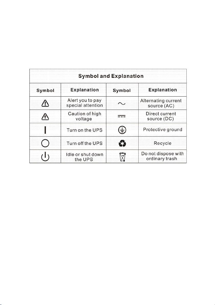
2. Description of Commonly Used Symbols ......................................... 5
3. Introduction .......................................................................................... 6
3.1 Feature ............................................................................................ 6
3.2 Electrical specifications ................................................................... 7
3.3 Operating Environment ................................................................... 8
3.4 Typical backup time (Typical values at 25°C in minutes)................ 9
3.5 Dimensions and weights ................................................................. 9
4. Installation .......................................................................................... 12
4.1 Moving to the installation site ........................................................ 12
4.2 Unpacking and inspection ............................................................. 12
4.3 Input and output power wires and protective earth ground
installation............................................................................................ 13
4.4 Operating procedure for connecting with the external battery......17
4.5 EPO Connection............................................................................ 18
5. Operation............................................................................................. 19
5.1 Display Panel................................................................................. 19
5.2 Operating mode............................................................................. 22
5.3 Turning on and Turning off UPS.................................................... 28
5.4 LCD operation ............................................................................... 29
6. Special function.................................................................................. 40
6.1 HE function .................................................................................... 40
6.2 Converter function ......................................................................... 41
6.3 Parallel function ............................................................................. 41
7. Trouble Shooting................................................................................ 47
7.1 Trouble Shooting According To Warning Indication ...................... 47
7.2 Trouble Shooting According To Fault Indication............................ 49

7.3 Trouble Shooting In Else Cases.................................................... 50
8. Battery Maintenance .......................................................................... 51
9. Communication Port.......................................................................... 52
9.1 USB Interface ................................................................................ 52
9.2 Dry contact Interface ..................................................................... 52
9.3 Intelligent slot................................................................................. 52
10. Software ............................................................................................ 53

1
1. Safety and EMC Instructions
Please read carefully the following user manual and the
safety instructions before installing the unit or using the
unit!
1.1 Installation
★
This is permanently connected equipment, and it must be
installed by qualified maintenance personnel.
★
Condensation may occur if the UPS is moved directly from a
cold to a warm environment. The UPS must be absolutely dry
before being installed. Please allow an acclimatization time of at
least two hours.
★
Do not install the UPS near water or in damp environment.
★
Do not install the UPS where it would be exposed to direct
sunlight or near heat.
★
Do not connect appliances or items of equipment which would
overload the UPS (e.g. laser printers, etc) to the UPS output.
★
Place cables in such a way that no one can step on or trip over
them.
★
Connect UPS with the earth reliably before connecting to the
building wiring terminal, and external battery source must also
be earthed.
★
An integral single emergency switching device which prevents
further supply to the load by the UPS in any mode of operation
should be provided in the building wiring installation.
★
An appropriate disconnect device as short-circuit backup
protection should be provided in the building wiring installation.
★
The equipment is powered by two sources: the mains source,
the internal battery or the external battery source.

2
★
With the installation of the equipment, the sum of the leakage
current of the UPS and the connected load does not exceed 5%
of rated value of input current.
★
Do not block ventilation openings in the UPS’s housing. Ensure
allow at least 50cm of space on front and rear of the UPS.
1.2 Operation
★
Do not disconnect the mains cable on the UPS or the building
wiring terminals during operation since this would remove the
protective earth from the UPS and all connected loads.
★
The UPS output terminal block may still be electrically lived
even if the UPS is not connected to the building wiring terminal,
for there is internal current source (batteries).
★
In order to fully disconnect the UPS, first turn the input breaker
in the “OFF” position, then disconnect the mains lead.
★
Indiscriminate operation of switches may cause output loss or
damage to equipment. Refer to instruction before conducting
any control.
★
While the UPSs work as a parallel system, the external parallel
cable should be reinforced insulation.
★
Ensure that no liquid or other foreign objects can enter the UPS.
1.3 Maintenance, servicing and faults
★
Do not remove the enclosure since the UPS operates with
hazardous voltages. It is to be serviced only by qualified
maintenance personnel.
★
Caution - risk of electric shock. Even after the unit is
disconnected from the mains power supply (building wiring
terminal), components inside the UPS are still connected to the
battery which are potentially dangerous.

3
★
Before carrying out any kind of service and/or maintenance,
isolate UPS and disconnect the batteries. Verify that no current
is present and no hazardous voltage exists in the capacitor or
BUS capacitor.
★
Batteries must be replaced only by qualified personnel.
★
Batteries have a high short-circuit current and pose a risk of
shock. Take all precautionary measures specified below and
any other necessary measures when working with batteries:
-
remove all jewellery, wristwatches, rings and other metal
objects
-
use only tools with insulated grips and handles.
★
When changing batteries, replace with the same quantity and
the same type of batteries.
★
Do not attempt to dispose of batteries by burning them. It could
cause explosion.
★
Do not open or destroy batteries. Effluent electrolyte can cause
injury to the skin and eyes. It may be toxic.
★
Replace the fuse only by a fuse of the same type and of the
same spec in order to avoid fire hazards.
1.4 Transport
★
★★
★
Please transport the UPS only in the original packaging to
protect against shock and impact.
1.5 Storage
★
The UPS must be stockpiled in the room where it is ventilated
and dry.

4
1.6 Standards
* Safety
IEC/EN 62040-1-1
* EMI
Conducted Emission..........................:IEC/EN 62040-2 Category C3
Radiated Emission.............................:IEC/EN 62040-2 Category C3
* EMS
ESD...................................................:IEC/EN 61000-4-2 Level 3
RS.....................................................:IEC/EN 61000-4-3 Level 3
EFT....................................................:IEC/EN 61000-4-4 Level 4
SURGE..............................................:IEC/EN 61000-4-5 Level 4
CS……………………………………...:IEC/EN 61000-4-6 Level 3
MS……………………………………..: IEC/EN 61000-4-8 Level 3
Voltage Dips……………………….....: IEC/EN 61000-4-11
Low Frequency Signals.....................:IEC/EN 61000-2-2
Warning: This is a product for cmmercial and industrial application in the
second environment-installation restrictions or additional measures may be
needed to prevente disturbances.

5
2. Description of Commonly Used Symbols
Some or all of the following symbols may be used in this manual. It is
advisable to familiarize yourself with them and understand their
meaning:

6
3. Introduction
This On-Line series is an uninterruptible power supply incorporating
double-converter technology. It provides perfect protection specifically
for computer equipments, communication servers, and data centers.
The double-converter principle eliminates all mains power
disturbances. A rectifier converts the alternating current from the utility
power to direct current. On the basis of this DC voltage, the inverter
generates an AC sinusoidal voltage, which constantly supplies the
loads. In the event of power failure, the maintenance-free batteries
power the inverter.
This manual covers the UPS listed as follows. Please confirm whether
it is the model you intend to purchase by performing a visual inspection
of the Model No. on the rear panel of the UPS.
“S” Model: Extended backup time
3.1 Feature
This series UPS is a new generation of UPS, which provides the
outstanding reliability, and most cost-performance ratio in the industrial.
Following benefit the product has:
True online double-conversion technology with high power
density, utility frequency independence, and generator
compatibility.
Output power factor is 0.9, perfect output sine waveform,
suitable almost all critical equipment.
High input power factor >0.99, overall high efficiency >0.92,
save power and wiring expense for user. Low input current
distortion, avoid power pollution.
Model No.
Type Model No.
Type
6K 6KS
10K Standard 10KS
Extended backup
time

7
Outstanding adaptability to the worst mains input condition.
Extra wide input voltage, frequency range and waveform, avoid
excessive dissipating limited battery energy.
Internal charger could be up to 4Amps to decrease recharging
time of battery. Optional external large charging current charger
which is up to 12Amps could be supplied.
N+X parallel redundancy to increase the reliability and flexibility.
Number of parallel operating UPS is up to 4.
HE mode with high efficiency >0.96, save power expense for
user.
Input or output ISO transformer compatibility.
Start-able without battery.
3.2 Electrical specifications
INPUT
Model No. 6K(S) 10K(S)
Phase Single
Voltage 176~276VAC
Frequency (45~55)/(54~66) Hz
Current(A)
THDI < 5% @ full load
Power Factor > 0.99 @ full load
OUTPUT
Model No. 6K(S) 10K(S)
Power rating 6kVA/5.4kW 10kVA/9kW
Voltage 208*/220/230/240×
(
1
士
1%
)
VAC
Frequency 50/60×
(
1±0.1
)
Hz (Battery mode)
Wave form sinusoidal

8
Load type PF 0.5~1, lagging
THDV < 2% @ full linear load
<5% @ full non linear load
Overload
In Line mode**:
10 min 105~125%
1 min 125~150%
10 s >150%
1 s >170%
In Battery mode:
2 min 105~125%
30 s 125~150%
1 s >150%
*Derating to 90% when the output voltage is adjusted to 208VAC.
**The overload capacity should be derated in Line mode while the circumstance
temperature is larger than 35 degree.
BATTERIES
Model No. 6K 10K
Internal BAT
number and type
20×12V 7Ah 20×12V 9Ah
Current
of external
BAT pack 30Amax 50Amax
3.3 Operating Environment
Operating Temperature 0
o
C to 45
o
C
Operating humidity < 95%
Altitude < 1000m*
Storage temperature -15
o
C to 50
o
C
*The load capacity should be derated 1% every 100m heightened on the basis
of 1000m.

9
3.4 Typical backup time (Typical values at 25°C in minutes)
Model No. 100 % Load 50 % Load
6K 5 ?
10K 5 ?
3.5 Dimensions and weights
Model No. Dimensions W×H×D
(mm)
Net Weight
(kg)
6K 260 x 708 x 550 89
6KS 260 x 708 x 550 34
10K 260 x 708 x 550 92
10KS 260 x 708 x 550 37

10
Fig. 3-1 Front view of 6K(S)/10K(S)

11
6K(S) 10K(S)
Fig. 3-2 Back View of 6K(S)/10K(S)

12
4. Installation
4.1 Moving to the installation site
The Innova series UPS has wheels making it easy to move the UPS
to the installation site after it has been unpacked. However, if the
receiving area is far from the installation site, it is recommended to
move the UPS by using a pallet jack or a truck before unpacking the
UPS.
4.2 Unpacking and inspection
1. At the installation site, the utmost care shall be taken when
removing the packaging in order to avoid damaging the equipment.
Cut the plastic poly-straps around the shipping container and
remove the corrugated carton and the PS foam on the top of the
UPS. With one or two people on each side of the UPS, lift the UPS
out of the pallet.
Warning: the plastic poly-straps around the shipping container
are under tension. While cutting, don’t face to them, they will
spring back and may cause eye injury.
The shipping materials are recyclable. After unpacking,
save them for later use or dispose of them appropriately.
The system may be installed and wired only by qualified
electricians in accordance with applicable saf
ety regulations!
When installing the electrical wiring, please note the nominal
amperage of your incoming feeder
.

13
2. Check all packaging materials to ensure that no items are missing.
The shipping package contains:
●A UPS
●A user manual
●A communication cable
●A parallel cable
●A parallel port cover plate
●Terminal connectors 12pcs
3. Inspect the appearance of the UPS to see if there is any damage
during transportation. Do not turn on the unit and notify the carrier
and dealer immediately if there is any damage or lacking of some
parts.
4.3 Input and output power wires and protective earth
ground installation
4.3.1 Notes for installation
1) The UPS must be installed in a location with good ventilation,
far away from water, inflammable gas and corrosive agents.
2) Ensure the air vents on the front and rear of the UPS are not
blocked. Allow at least 0.5m of space on each side.
3) Condensation to water drops may occur if the UPS is unpacked
in a very low temperature environment. In this case it is
necessary to wait until the UPS is fully dried inside out before
proceeding installation and use. Otherwise there are hazards of
electric shock.
4) The additional side mounting brackets
(
optional accessory
)
can
be fixed to obtain grater stability of the UPS enclosure. See Fig.
4-5.

14
Fig. 4-5 Additional stability
4.3.2 Installation
Use cable cross section and protective device specification
Model 6k 10k
Protective earthing conductor
Min cross section 4mm
2
(10AWG)
10 mm
2
(6AWG)
Input L, N, G
Min conductor cross section
4mm
2
(10AWG)
10 mm
2
(6AWG)
Input breaker 50A/250VAC 80A/250VAC
Input fuse 60A/250VAC 90A/250AC
Output L,N,
Min conductor cross section 4mm
2
(10AWG)
10 mm
2
(6AWG)
External Battery Cabinet
Positive Pole(+), Negative pole(-),
Neutral Pole
Min conductor cross section
4mm
2
(10AWG)
10 mm
2
(6AWG)
External Battery Cabinet Fuse
in Positive Pole(+), Negative pole(-),
Neutral Pole
60A/240VDC 90A/240VDC
For safety, please cut off the mains power switch before
installation
!

15
External Battery Cabinet Breaker
in Positive Pole(+), Negative pole(-),
Neutral Pole
60A/240VDC 90A/240VDC
Backfeed protection device A 2-pole disconnection device with
80A/250VAC, less than 15s break
time and min. 1.4mm clearance
should be used in final installation for
backfeed protection.
Torque for fixing above terminals 3.95~4.97Nm
(35~44 1b in)
2) No matter the UPS is connected to the utility power or not, the
output of the UPS may be electrically live. The parts inside the
unit may still have hazardous voltage after turning off the UPS.
To make the UPS have no output, power off the UPS, and then
cut off the utility power supply, wait the UPS shut down
completely.
3) Open the terminal block cover located on the rear panel of UPS,
please refer to the appearance diagram.
4) For 6KVA UPS, it is recommended to select the UL1015
10AWG/4mm
2
or other insulated wire which complies with AWG
Standard for the UPS input and output wirings.
5) For 10KVA UPS, it is recommended to select the UL1015
6AWG/10mm
2
or other insulated wire which complies with AWG
Standard for the UPS input and output wirings.
6) Ensure the capacity of mains power supply. Do not use the wall
receptacle as the input power source for the UPS, as its rated
current is less than the UPS’s maximum input current.
Otherwise the receptacle may be burned and destroyed.
7) The protective earth ground wire should be installed first
according to the following diagram. It is better to use green wire
or green wire with yellow ribbon wire.

16
8) Connect other input and output wires to the corresponding input
and output terminals according to the following diagram.
9) It is recommended to use the accessorial terminal connectors
which can be compacted on the wires tightly, to ensure the
connection between the wires and the terminal block is reliable.
Fig. 4-6 Input and output Terminal Block wiring diagram
Important notes: If the UPS is used in single mode, JP1 and JP2
must be connected. If the UPS is used in parallel mode, the Jumper
between JP1 and JP2 must be removed.
10) Install an output breaker between the output terminal of UPS
and the load, and the breaker should with leakage current
protective function if necessary.
11) Turn off all the loads first before connecting the load with the
UPS, then perform the connection and finally turn on the loads
one by one.
12) After completing the installation, check all the wires is
connected correctly and tightly.
13) Suggest charging the batteries for 8 hours before use. After
installation, turn on the mains power switch and turn the input
breaker in the “ON” position, the UPS will charge the batteries
automatically. It can also use the UPS immediately without
charging the batteries, but the backup time may be less than the
standard value.

17
14) If it is necessary to connect the inductance load such as a
monitor or a laser printer to the UPS, the start-up power should
be used for calculating the capacity of the UPS, as its start-up
power consumption is too big to make the UPS which capacity
is small fail easily.
4.4 Operating procedure for connecting with the external
battery
1. The nominal DC voltage of external battery pack is 240VDC. Each
battery pack consists of 20 pieces of 12V maintenance free
batteries in series. To achieve longer backup time, it is possible to
connect multi-battery packs, but the principle of “same voltage,
same type” should be strictly followed.
2. For 6KVA, select the UL1015 10AWG/4mm
2
respectively or other
insulated wire which complies with AWG Standard for the UPS
battery wirings.
3. For 10KVA, select the UL1015 6AWG/10mm
2
respectively or other
insulated wire which complies with AWG Standard for the UPS
battery wirings.
4. The external battery pack must be independent for each UPS. It is
forbidden that two UPSs use same external battery pack.
5. The procedure of installing battery pack should be complied with
strictly. Otherwise it may encounter the hazardous of electric
shock.
1) Ensure the UPS is not powered on and the mains input
breaker is set in the “OFF” position.
2) A DC breaker must be installed between the external battery
pack and the UPS. The capacity of breaker must be not less
than the data specified in the general specification.
This manual suits for next models
4
Table of contents
Popular UPS manuals by other brands

Falcon
Falcon SG700RM-1SC user manual

CyberPower
CyberPower 649532210046 Specification sheet

Schrack Technik
Schrack Technik GENIO Dual Power Series Installation and use manual

Riello UPS
Riello UPS GUARD TOWER GTT 6000 quick guide

Eaton
Eaton DIN24240DC Advanced user's guide

Gamatronic
Gamatronic Centric 3x480 Vac installation guide