INO-ROPE I-BONE User manual

Original textile solutions
High-tech fibers at the core of our innovations
MODE D’EMPLOI
-
USER’S MANUAL


Butée de drisse Ino-Stopper
Mode d’emploi
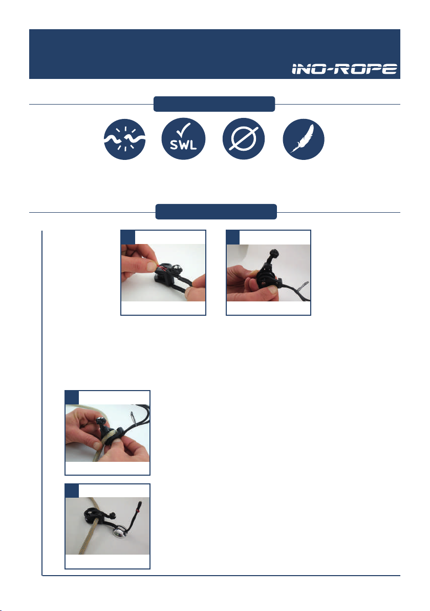
1/ Présenter la
butée de drisse par
son côté le moins
large sur un œil
épissé et insérer
l’œil dans la gorge
basse.
2/ Tourner d’1/4
de tour de sorte
à ce que les deux
brins de l’œil épissé
soient engagés dans
les gorges prévues à
cet eet.
3/ Bien posionner
la butée de drisse à
la perpendiculaire
du cordage pour
une meilleure
ecacité.
SPECIFICATIONS
INSTALLATION
La butée de drisse Ino-Stopper doit être installée dans un œil épissé ajusté au plus
serré.
La taille de l’œil de l’œil épissé ne doit pas excéder la largeur de la butée :
- 25mm pour une drisse de diam. 6mm
- 30mm pour une drisse de diam. 8mm
- 35mm pour une drisse de diam. 10mm
- 40mm pour une drisse de diam. 12mm
Existe pour drisses de
diamètre 6, 8, 10 et
12mm
Diam. 6: 3gr
Diam. 8: 7gr
Diam.10: 16gr
Diam.12: 20gr
123
3

Ino-Stopper halyard stopper
Instrucons
1/ Place the halyard
stopper with its
narrowest side onto
a spliced eye and
insert the eye in the
lower groove.
2/ Make a ¼ turn to
let the two strands
of the spliced eye
enter the intended
groove.
3/ For the most
eciency, posion
the halyard stopper
perpendicularly to
the line.
SPECIFICATIONS
INSTALLATION
The Ino-Stopper halyard stopper must be set up in a spliced eye adjusted as ghtly
as possible.
The size of the eye of the spliced eye must not be wider than the stopper’s width:
- 25mm for a 6mm halyard
- 30mm for an 8mm halyard
- 35mm for a 10mm halyard
- 40mm for a 12mm halyard
Available for halyards
of 6, 8, 10 and 12mm
diameter
Diam. 6: 3gr
Diam. 8: 7gr
Diam.10: 16gr
Diam.12: 20gr
123
4

5
Poulie ouvrante Ino-Snatch-Block
Mode d’emploi
SPECIFICATIONS
INSTALLATION
Charge de
rupture :
1200kg
Charge de
travail :
400 kg
Diam. Max :
10 mm
Poids :
28 gr.
- Ouvrir la manille
texle en vous
servant de la ree
d’ouverture facile.
- Ouvrir la poulie en
faisant pivoter les deux
pares de la poulie de
manière à avoir accès
a la gorge du réa (une
rotaon de 90° sut).
- Insérer le cordage sur le réa.
- Refermer les joues en les posionnant bien face à
face et jusqu’au « clic ».
- Passer la manille texle autour de son point
d’accroche.
- Refermer la manille texle.
- Rincer votre Ino-Snatch-Block à l’eau claire.
SPECIFICATIONS
INSTALLATION
1 2
3
4
6
Ino-Snatch-Block
Instrucons
SPECIFICATIONS
INSTALLATION
- Open the so shackle with
the easy opening pull.
- Open the block by rotang
both parts of the block in order
to have access to the sheave’s
groove (a 90° rotaon is
enough).
- Insert the line on the sheave.
- Close cheeks making sure they align, unl
you hear the clicking sound.
- Pass the so shackle around its anchor
point.
- Close the so shackle.
- Rinse your Ino-Snatch-Block with clean
water.
3
4
1 2
BL :
1200kg
SWL :
400 kg
Diam. Max :
10 mm
Weight :
28 gr.

7
Padeye Ino-Rope-Padeye
Mode d’emploi
- A l’aide d’une scie cloche,
percer le pont au diamètre
adapté.
- Réaliser un cordon de joint
polyuréthanne autour du
perçage.
- Insérer la padeye en orientant
son accroche dans le sens de
l’eort.
- Une fois correctement
posionnée, visser l’écrou
intérieur, ce dernier est
asymétrique an de s’adapter à
plusieurs épaisseurs de pont.
- Serrer légèrement l’écrou.
- Aendre que le joint
polyuréthanne soit sec puis
serrer fermement l’écrou en
bloquant la padeye.
SPECIFICATIONS
INSTALLATION
P-4: WL 800kg
P-6: WL 1800kg
P-8: WL 3000kg
P-4: 98gr
P-6: 96gr
P-8: 26gr
1
2
1
2
2
4
3

8
Ino-Padeye
Instrucons
- Cut the appropriate size hole
in the deck.
- Fill and seal the cut surfaces
with polyurethane sealant.
- Insert the padeye by
direcng its anchor in the
intended load direcon.
- Once it is correctly
posioned, screw the inner
nut, this is asymmetrical in
order to adapt to dierent
deck widths.
- Tighten the nut lightly.
- Once the polyurethane seal
has dried, close the nut rmly
by blocking the padeye.
SPECIFICATIONS
INSTALLATION
P-4: WL 800kg
P-6: WL 1800kg
P-8: WL 3000kg
P-4: 98gr
P-6: 96gr
P-8: 26gr
1
2
1
2
2
4
3

9
Poulies Ino-Block
Mode d’emploi
SPECIFICATIONS
INSTALLATION
1
2
1
24
Rincer à
l’eau claire
après chaque
utilisation
Charge de
rupture
(tonnes)
Charge de
travail
(tonnes)
Cordage
Accepté
(mm)
Poids
(grammes)
Modèle IB
2.4
43
6-10
0.8
3.6
48
6-10
1.2
5.4
130
8-14
1.8
7.2
135
10-14
2.4
9
245
10-17
3
12
250
10-17
4
15
400
12-20
5
18
410
12-20
6
Les poulies INO-BLOCK sont vendues avec un lashing Dyneema® épissé
d’un côté. Avant de commencer, assurez-vous que la padeye n’a pas de
bord tranchant. Dans le cas contraire, le lashing peut s’user et casser
subitement, entraînant des dommages à votre bateau, à vos équipiers ou à
vous-même. La xaon de votre Ino-Block est constuée de deux boucles
sur le dessus de la poulie. Pour éviter tout dommage à votre Ino-Block,
eectuer le lashing en passant par les deux boucles simultanément.
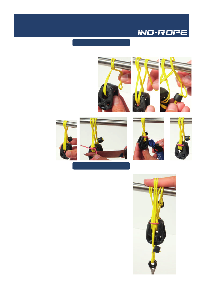
1/ Pour xer votre Ino-Block, commencer par une tête d’alouee sur les
deux boucles du loop de la poulie.
2/ Passer ensuite dans la cadène (padeye) puis sous les deux boucles du
loop.
3/ Répéter 2 fois cee opéraon pour avoir 3 tours de lashing.
4/ Faire les demi clés avec le brin qui ressort de la poulie.
5/ Finir avec un demi nœud, couper puis brûler.
6/ Votre poulie est prête a l’emploi.
5 6
2
3
GARANTIES
La garane couvre tout défaut d’origine matérielle ou d’assemblage constaté dans un délai de un an
à compter de la date d’achat par le client nal. Le scker de marque (ex: ”3.6”) fait oce de garane.
Si le scker est décollé, le client nal sera intégralement responsable pour tout dommage.
L’axe texle doit être vérié chaque année ou tout les 10.000 miles. Commandez vos pièces de
rechange sur inorope.com
Pour bénécier d’un an d’extension de garane, pensez à notre service après vente pour la
maintenance de vos poulies. Plus d’informaons sur inorope.com.

10
Ino-Block
Instrucons
SPECIFICATIONS
INSTALLATION
1
2
1
24
NO-BLOCK are sold with a lashing already spliced at one end. Before you
start, make sure you e it to a padeye with round edges. Otherwise, it
may damage the line and break suddenly causing damage to your vessel,
personal injury or death.
The padeye on the INO-BLOCK consists in two loops on the top of the block.
You may pass under both loops simultaneously, otherwise you will damage
the INO-BLOCK.
1/ To e your block, start with a lark’s head on the two loops of the block.
2/ Then, pass through the padeye and again under the two loops of the
block.
3/ Repeat this operaon 2 mes to have 3 rounds of lashing.
4/ Tie a half hitch with the line coming from the block.
5/ Finish with an overhand knot, then cut and burn it.
6/ Your block is ready to use.
5 6
2
3
WARRANTY INFORMATION
The warranty covers any original material or workmanship defects declared within one year of the
date of receipt of the product by the end user. The brand sckers (ex: ”3.6”) is a warranty seal. If
removed, the end user will be responsible for any damage or defects.
The axle loop should be checked every year or every 10,000 miles. Spare parts can be ordered on
inorope.com.
Our aer-sales service can do the maintenance of your block and extend for one more year the
warranty. Find out more on inorope.com.
Rince with
fresh water
after use
Breaking
Load
(tons)
Safe Working
Load
(tons)
Rope Accepted
(mm)
Weight
(grams)
Model IB
2.4
43
6-10
0.8
3.6
48
6-10
1.2
5.4
130
8-14
1.8
7.2
135
10-14
2.4
9
245
10-17
3
12
250
10-17
4
15
400
12-20
5
18
410
12-20
6

Ino-Block 0.6 & 1.2
Mode d’emploi
SPECIFICATIONS
Rinse with
fresh water
after use
and inspect
line every
time you sail
Les INO-BLOCK LIGHT 0.6 et INO-BLOCK LIGHT 1.2 sont vendus avec un lashing ou
une I-CONNECT. Ce manuel d’ulisaon décrit les diérents modes d’assemblage
(0 °, 90 °, I-CONNECT, large diamètre et opon ringot).
Avant de commencer, assurez-vous d’accrocher la poulie sur un pontet avec les
bords arrondis. Sinon, des arêtes vives peuvent endommager la tresse pouvant
alors casser subitement causant des dommages à votre navire, blessure
personnelle ou mort.
L’axe texle et l’aache au pontet est fait avec le même morceau de Dyneema
®. INO-ROPE ne sera pas tenu responsable des défauts en raison d’une ulisaon
inappropriée ou d’un assemblage défectueux. Veuillez contacter votre revendeur
local pour toute aide sur le assemblage ou pour d’autres informaons.
Breaking
Load
(tons)
Safe Working
Load
(tons)
Rope Accepted
(mm)
Weight
(grams)
Model IB
0.6
8
3-8
0.2
1.2
19
4-10
0.4
Installaon lashing à 0° (poulie et axe de xaon dans le même axe) :
1/ Pour aacher votre poulie, passez une extrémité de la tresse
à travers la poulie (à travers le réa et l’écarteur).
2/ Puis exécutez cee même opéraon autour de l’axe de
xaon (dans le même sens de rotaon).
3/ Répétez cee opéraon 3 fois an d’avoir un lashing à 4 brins
de chaque côté, merci de respecter le sens de rotaon à chaque
tour.
4/ Une n du lashing doit venir de la poulie et l’autre de la
xaon.
5/ Ensuite, ajustez l’espacement entre votre poulie et la xaon
en rant ou en relâchant les deux extrémités (ne rapprocher la
poulie trop près de la xaon).
6/ Avec le brin venant de la poulie, faites 3 demi-clés proche de
la xaon (ne pas oublier de serrer l’autre brin du lashing dans
la demi-clé).
7/ Avec le brin venant de la xaon, faites 3 demi-clés proche
de la poulie.
8/ Finissez les deux dernières demi-clés par un nœud simple,
coupez et bruler le bout du nœud.
9/ Vous devez obtenir un lashing avec 4 brins de chaque côté,
verrouillé avec trois demi-clés et un nœud simple de chaque
côté.
10/ Sécuriser ensuite votre lashing à votre poulie avec le pet
boute fournis avec la poulie. Aachez-le avec un nœud plat
11/ Votre poulie est prête à être ulisé.
INSTALLATION À 0°
11
Rincer à l’eau claire
après ulisaon
et inspecter
la tresse avant
chaque navigaon
Charge
de rupture
(tonnes)
Charge
de travail
(tonnes)
Cordage
accepté
(mm)
Poids
(grammes)

12
Ino-Block 0.6 & 1.2
Mode d’emploi
INSTALLATION À 90°
Installaon lashing à 90° (poulie perpendiculaire à l’axe de xaon) :
1/ Pour aacher votre poulie, passez une extrémité de la
tresse à travers la poulie (à travers le réa et l’écarteur).
2/ Puis exécutez cee même opéraon autour de l’axe de
xaon
3/ Passez ensuite ce brin à travers la poulie dans le même
côté que précédemment.
4/ Répétez cee opéraon 3 fois an d’avoir un lashing à 4
brins de chaque côté.
5/ Une n du lashing doit venir de la poulie et l’autre de la
xaon.
6/ Ensuite, ajustez l’espacement entre votre poulie et la
xaon en rant ou en relâchant les deux extrémités (ne
rapprocher la poulie trop près de la xaon).
7/ Avec le brin venant de la poulie, faites 3 demi-clés proche
de la xaon (ne pas oublier de serrer l’autre brin du lashing
dans la demi-clé).
8/ Avec le brin venant de la xaon, faites 3 demi-clés proche
de la poulie.
9/ Finissez les deux dernières demi-clés par un nœud simple,
coupez et bruler le bout du nœud.
10/ Vous devez obtenir un lashing avec 4 brins de chaque
côté, verrouillé avec trois demi-clés et un nœud simple de
chaque côté.
11/ Sécuriser ensuite votre lashing à votre poulie avec le pet
boute fournis avec la poulie. Aachez-le avec un nœud plat
12/ Votre poulie est prête à être ulisé.
INSTALLATION AUTOUR D’UN OBJET À DIAMÈTRE LARGE
Installaon lashing autour d’un objet à diamètre large :
1/ Pour aacher votre poulie, passez une extrémité de la tresse à travers
la poulie (à travers le réa et l’écarteur).
2/ Croisez le brin à chaque fois que vous passez autour de l’objet et de
la poulie.
3/ Passez ensuite ce brin autour de la xaon (mât, bôme, etc…) en
croisant les brins.
4/ Passez ce brin ensuite à travers la poulie toujours en croisant les brins.
5/ Répétez cee opéraon 3 fois an d’avoir un lashing à 4 brins de
chaque côté.
6/ Une n du lashing doit venir de la poulie et l’autre de la xaon.
7/ Ensuite, ajustez l’espacement entre votre poulie et la xaon en rant
ou en relâchant les deux extrémités (ne rapprocher la poulie trop près
de la xaon).
8/ Avec le brin venant de la poulie, faites 3 demi-clés proche de la
xaon (ne pas oublier de serrer l’autre brin du lashing dans la demi-clé).
9/ Avec le brin venant de la xaon, faites 3 demi-clés proche de la
poulie.
10/ Finissez les deux dernières demi-clés par un nœud simple, coupez et
bruler le bout du nœud.
11/ Vous devez obtenir un lashing avec 4 brins de chaque côté, verrouillé
avec trois demi-clés et un nœud simple de chaque côté.
12/ Sécuriser ensuite votre lashing à votre poulie avec le pet boute
fournis avec la poulie. Aachez-le avec un nœud plat
13/ Votre poulie est prête à être ulisé.
Ino-Block 0.6 & 1.2
Mode d’emploi
OPTION I-CONNECT
Installaon I-CONNECT :
1/ Pour aacher votre poulie, passez l’extrémité de la
manille (avec l’œil) à travers la poulie (à travers le réa
et l’écarteur).
2/ Croisez le brin à chaque fois que vous passez autour
de l’objet et de la poulie.
3/ Passez ensuite ce brin autour de la xaon (mât,
bôme, etc…) en croisant les brins.
4/ Répétez cee opéraon une nouvelle fois pour
obtenir deux tours dans la manille texle. Essayez de
maintenir les brins parallèles.
5/ Fermez la manille texle, en ouvrant l’œil et en y
insérant la boule à travers. Fermez l’œil en rant fort sur
votre poulie.
6/ Sécuriser ensuite votre I-Connect à votre poulie avec
le pet boute fournis avec la poulie. Aachez-le avec un
nœud plat
7-Votre poulie est prête à être ulisé.
OPTION RINGOT
Installaon ringot (Le ringot peut être ajouté au lashing ou à une
I-Connect) :
1/ Une opon ringot est disponible. Elle consiste à une
I-connect xée autour du point de xaon avec un seul
tour.
2/ Passez votre ringot (I-Connect) autour de votre point
de xaon et fermez l’I-Connect en ouvrant l’œil et en y
insérant la boule à l’intérieur. Fermez l’œil en rant fort
sur votre ringot.
3/ N’oubliez pas d’insérer votre ringot dans le boute de
sécurité.
4/ Votre ringot est prêt à être ulisé.
13
14
Ino-Block 0.6 & 1.2
Mode d’emploi
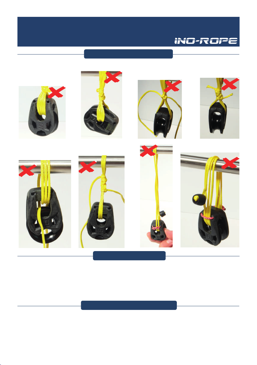
ASSEMBLAGE INCORRECT
Exemple d’assemblage incorrect :
Absence du boute de blocage
sur la poulie
L’axe texle n’est pas posionné
autour de l’anneau
Manque de tours sur le
lashing (2 tours au lieu de 4
tours)
Manque d’un tour
sur l’I-Connect (1
tour réalisé au lieu
de 2 tours)
Mauvais assemblage de l’I-Connect.
Les tours ne sont pas croisés
Le dernier nœud n’a pas
été coupé et brulé an
sécuriser le lashing de
chaque coté
Absence d’une demi-clé sur
le lashing (un par extrémité
au lieu de 3 par extrémité)
MAINTENANCE
Inspecter la tresse pour des dommages de froement ou d’UV après chaque navigaon. Remplacer la tresse endommagée
immédiatement.
Remplacez la tresse sans dommages visibles chaque année. Les pièces de rechange peuvent être commandées sur ino-
rope.com.
Nos poulies sont conçues pour un entreen minimal. Cependant, un entreen minimum est nécessaire pour donner la
meilleure sasfacon et se conformer à la garane INO-ROPE. Gardez votre équipement propre et libre de tourner en le
rinçant fréquemment à l’eau claire. Neoyer votre poulie périodiquement avec de l’eau et du savon.
INFORMATION DE GARANTIE
La garane couvre tous les défauts de fabricaon ou matériels déclarés dans un délai d’un (1) an à compter de la date de
récepon du produit par l’ulisateur nal.
L’axe texle doit être vérié chaque année ou tous les 10 000 milles. Les pièces de rechange peuvent être commandées
sur ino-rope.com.
Notre service après-vente peut eectuer la maintenance de votre poulie et prolonger la garane pour une (1) année
supplémentaire.

Ino-Block 0.6 & 1.2
Instrucons
SPECIFICATIONS
Rinse with
fresh water
after use
and inspect
line every
time you sail
INO-BLOCK 0.6 and INO-BLOCK 1.2 are sold with a lashing or an
I-CONNECT. This user manual describes dierent ways of assembling (0°,
90°, I-CONNECT, large diameter and becket opon)
Before you start, make sure you e it to a padeye with round edges.
Otherwise, sharp edges may damage the line and break suddenly causing
damage to your vessel, personal injury or death.
The texle axle and the aachment to a padeye is made with the same
piece of Dyneema
®
.
INO-ROPE will not be held responsible for any defects
due to inappropriate use or a faulty assembly.
Please contact your local dealer for any help on the assembly or for
further informaon.
Breaking
Load
(tons)
Safe Working
Load
(tons)
Rope Accepted
(mm)
Weight
(grams)
Model IB
0.6
8
3-8
0.2
1.2
19
4-10
0.4
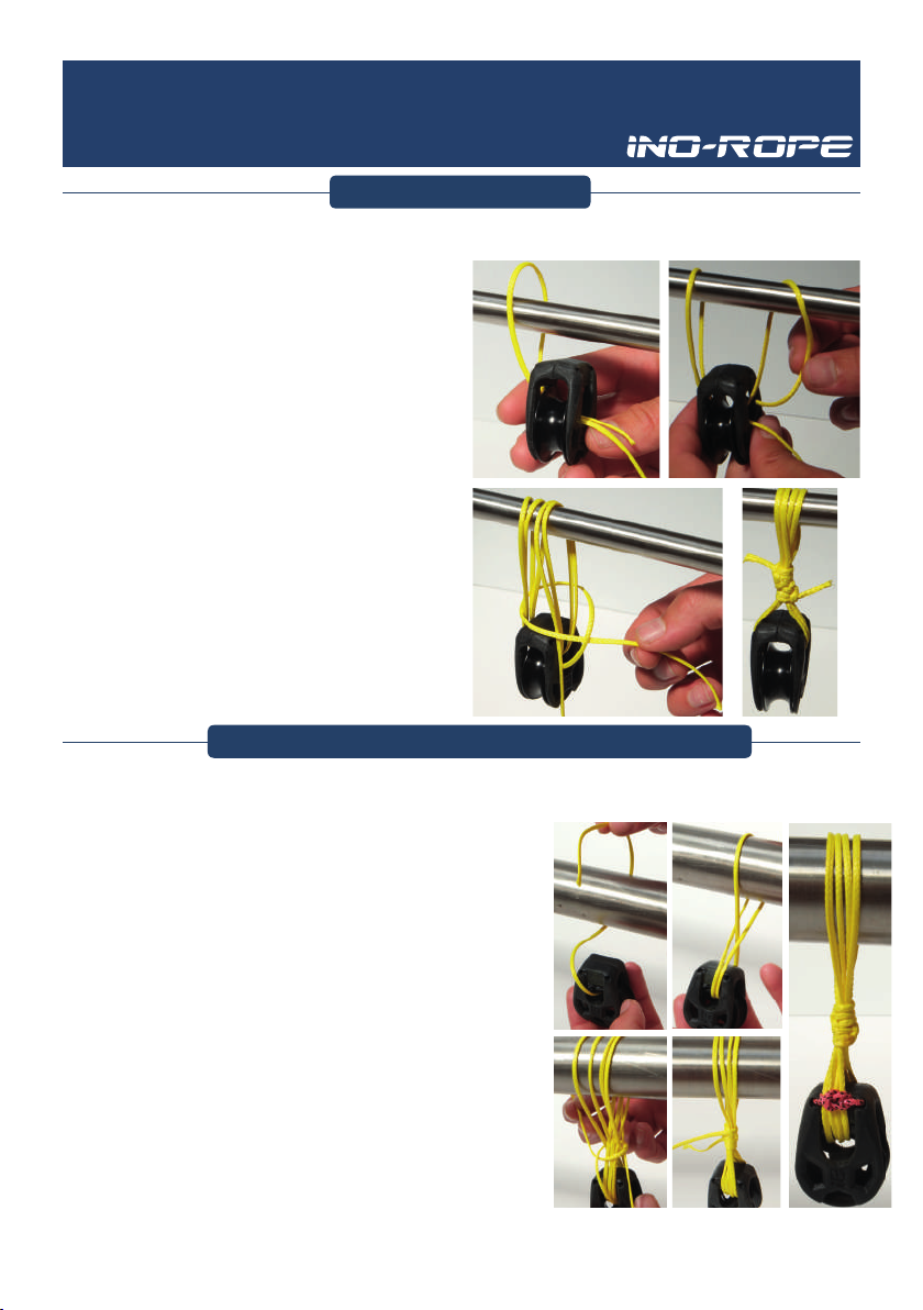
Lashing Installaon at 0° (Block and Bail In-Line):
1/ To e your block, run one end of the line through the block
(through sheave and spacer).
2/ Then run this same end through your xaon or around the
bail (in the same direcon of rotaon).
3/ Repeat this operaon 3 mes to have a lashing with 4 loops
each side, please respect the direcon of rotaon for all the
rounds.
4/ One end of the lashing comes from the block and the other
from the xaon.
5/ Then, adjust spacing of your block by pulling or releasing the
two ends (do not e too close to the xaon).
6/ With the line coming from the block , e 3 half hitches close
to the xaon (don’t forget to ghten the other end of the
lashing inside the half hitch).
7/ With the line coming from the xaon, e 3 half hitches close
to the block.
8/ Finish the two half hitches with a square knot or granny knot,
then cut and burn them.
9/ You should obtain a lashing with 4 loops each side, locked
with three half hitches each side plus square knots.
10/ Then secure your lashing strands to the block with the
smaller line provided with the block. Tie it with a square knot
or «granny knot»
11/ Your block is ready to use.
INSTALLATION
15
16
Ino-Block 0.6 & 1.2
Instrucons
INSTALLATION AT 90°
Lashing Installaon (Block at 90° to Bail):
1/ To e your block, run one end of the line through the block
(through sheave and spacer)
2/ Then run this same end through your xaon or around
the bail
3/ Run this end through the block back in the same side of
block.
4/ Repeat this operaon 3 mes to have a lashing with 4
loops each side of the block.
5/ One end of the lashing comes from the block and the
other from the xaon or bail.
6/ Then, adjust spacing of your block by pulling or releasing
the two ends (do not e too close to the xaon).
7/ With the line coming from the block , e 3 half hitches
close to the xaon (don’t forget to ghten the other end of
the lashing in the half hitch)
8/ With the line coming from the xaon, e 3 half hitches
close to the block.
9/ Finish the two half hitches with a square knot or granny
knot, then cut and burn them.
10/ You should obtain a lashing with 4 loops each side,
locked with three half hitches each side plus square knots.
11/ Then secure your lashing strands to the block with the
smaller line provided with the block. Tie it with a square knot
or «granny knot»
12/ Your block is ready to use.
INSTALLATION WITH LARGE DIAMETER OBJECT
Lashing Installaon on large object:
1/ To e your block, run one end of the line through the block (through
sheave and spacer)
2/ Cross line each me you pass around the object and the block.
3/ Run the line around the xaon by crossing line (boom, mast etc ...)
4/ Run this end through the block by crossing lines.
5/ Repeat this operaon 3 mes to have a lashing with 4 loops each side
of the block.
6/ One end of the lashing comes from the block and the other from the
xaon or bail.
7/ Then, adjust spacing of your block by pulling or releasing the two ends
(do not e too close to the xaon).
8/ With the line coming from the block , e 3 half hitches close to the
xaon (don’t forget to ghten the other end of the lashing in the half
hitch)
9/ With the line coming from the xaon, e 3 half hitches close to the
block.
10/ Finish the two half hitches with a square knot or granny knot, then
cut and burn them.
11/ You should obtain a lashing with 4 loops crossing each side, locked
with three half hitches each side plus square knots.
12/ Then secure your lashing strands to the block with the smaller line
provided with the block. Tie it with a square knot or «granny knot»
13/ Your block is ready to use.

Ino-Block 0.6 & 1.2
Instrucons
I-CONNECT OPTION
I-CONNECT installaon (so shackle):
1/ To e your block, run the end of the shackle with
the eye through the block (through sheave and spacer).
2/ Cross line each me you pass around the object and
the block.
3/ Run this end around the xaon point (boom, mast
etc ...)
4/ Repeat previous operaons once more to obtain
a double laps texle shackle . Try to keep the strands
parallel.
5/ Close the texle shackle, by opening the eye and put
the ball through this eye. Close the eye by pulling hard
on the block.
6/ Then secure your double laps texle shackle to the
block with the smaller line provided with the block. Tie it
with a square knot or «granny knot»
7/ Your block is ready to use.
BECKET OPTION
Becket Installaon (the becket can be in addion of a lashing or an
I-CONNECT):
1/ A becket opon is available. It consists of an I-CONNECT
xed around the bail or xaon point with only one lap.
2/ Run your becket (I-CONNECT) around your bail or xa-
on point and close the I-CONNECT by opening the eye
and put the ball through this eye. Close the eye by pulling
hard on the becket.
3/ Don’t forget to include the becket behind the secured
line.
4/ Your becket is ready to use
17

18
Ino-Block 0.6 & 1.2
Instrucons
INCORRECT ASSEMBLY
Example of incorrect assembly:
Missing line to lock the
lashing on the block
Missing texle axle around the
sheave
Missing laps on lashing (two
laps instead of fours laps)
Missing lap on
I-Connect (one lap
instead of two laps)
Wrong assembly of I-connect. Laps
are not crossed.
Missing square knot
burned to secure the half
hitches
Missing half hitches on
lashing (one per extremity
instead of 3 per extremity)
MAINTENANCE
Inspect lashing line for chafe or UV damage every me you sail. Replace damaged line immediately.
Replace line with no visible damage every year. Spare parts can be ordered on ino-rope.com
Our blocks are designed for minimal maintenance. However, some upkeep is required to give the best service and comply
with INO-ROPE limited warranty. Keep your equipment clean and free-running by frequently rinsing with fresh water.
Periodically clean with soap and water.
WARRANTY INFORMATION
The warranty covers any original material or workmanship defects declared within one year of the date of receipt of the
product by the end user. The axle loop should be checked every year or every 10,000 miles. Spare parts can be ordered
on ino-rope.com.
Our aer-sales service can do the maintenance of your block and extend the warranty for one more year.

I-Bone
Mode d’emploi
ATTENTION
INSTALLATIONCONDITION D’ASSEMBLAGE
SPECIFICATIONSSPECIFICATIONS
Il est fortement recommandé de faire installer les I-Bone par un mateloteur professionnel.
INO-ROPE n’est peut être tenu pour responsable pour tout accident lié à une mauvaise
installaon ou utlisaon de l’I-Bone. Avant de commencer, vériez que vous avez choisi
l’I-Bone correspondant à la charge de travail et au diamètre du câble texle.
L’I-Bone doit être uniquement en contact avec du texle. Un I-Bone fait généralement la
connecon entre deux épissures simples ou doubles tresses.
L’oeil autour de du diamètre intérieur de l’I-Bone doit être le plus serré possible et l’I-Bone
doit être cousu à la tresse.
L’I-Bone doit être choisi en foncon de sa charge de travail, après un I-Bone de taille
supérieure peut être seleconné correspondant au diamètre de tresse. Si l’I-Bone fait la
connecon entre deux yeux, il est recommandé de faire une longueur d’oeil égale à la
longueur de l’I-Bone.
Charge de
rupture*
(tonnes)
2
Poids
(g)
6
Diamètre
tresse
(mm)
6-81.0
I-BONE 6 2.5 92 5
38 8-10
1.5 2.5 12 33
5.4 19 10-122.7 2.5 16 41
7.2 30 12-143.6 2.5 18.5 49
Charge
maximale
d’utilisation*
(tonnes)
I-BONE 8
I-BONE 10
I-BONE 12
Longueur
(mm)
Diamètre du
perçage pour la
couture (mm)
Diamètre
central (mm)
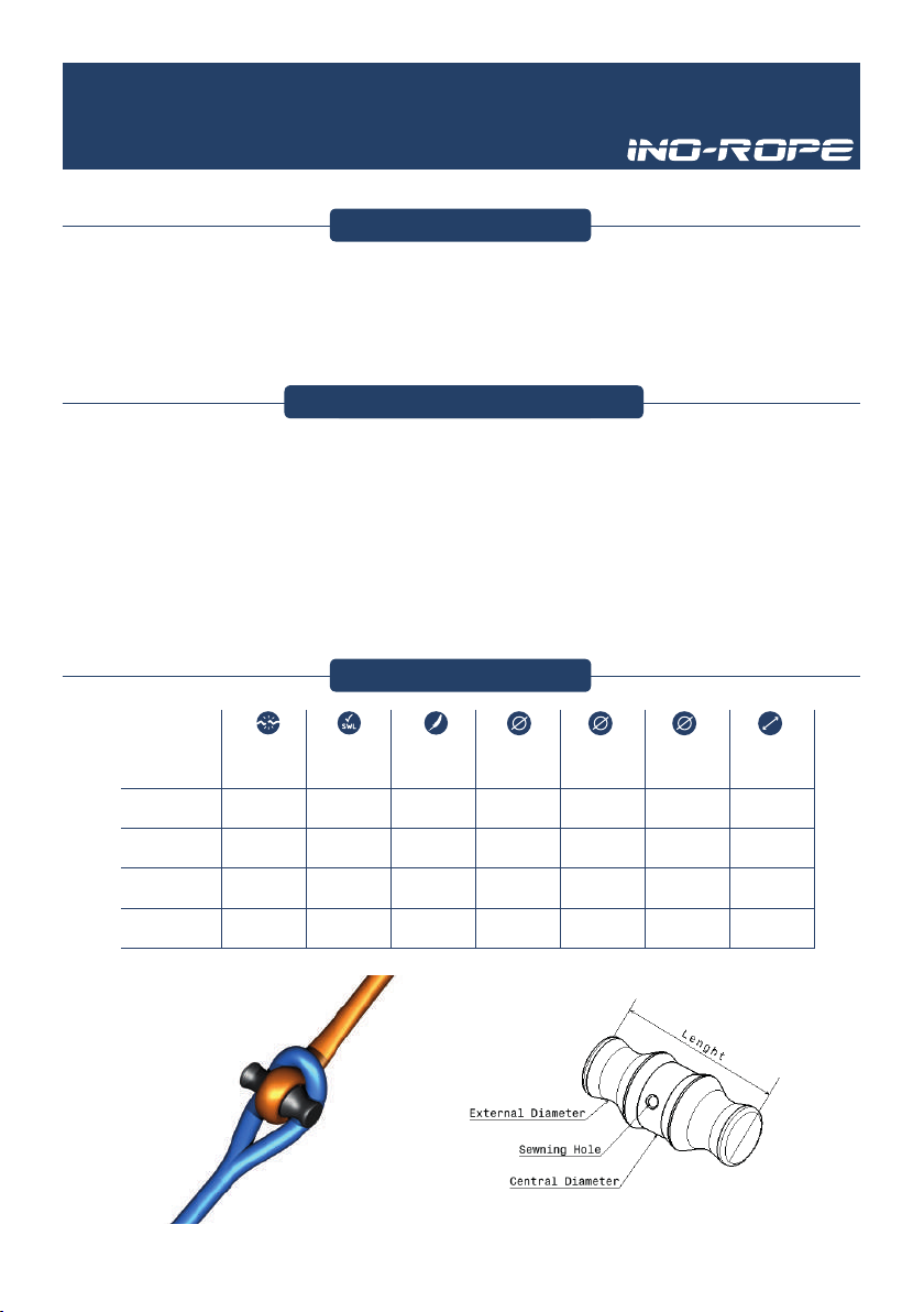
* La charge de rupture et la charge de travail ont été déterminé et testé à partir d’une installation classique de t-bone comme indiqué sur l’image ci-dessous.
Montage courant d’un I-BONE Schéma I-BONE
19
20
I-Bone
Instrucons
WARNINGS
INSTALLATIONMOUNTING CONDITIONS
SPECIFICATIONSSPECIFICATIONS
It’s highly recommended to have your I-BONE installed by a professional rigger. INO-ROPE
will not be held responsible for any defects due to inappropiate use or a faulty assembly.
Before you start, make sure you have chosen the correct model of I-BONE that corresponds
to the working load and the diameter of your texle cable.
The I-BONE must only be in contact with rope. It is used to connect two splice eyes of single
or double braided rope.
The center splice has to be ghtened as close as possible from the I-BONE and the eye has
to be sewn with hole of the I-bone.
In rst, the I-BONE has to chose in funcon of the working load, aer an upper I-BONE can
be chose for the diameter. If the I-BONE connects two eyes, it is recommended to have a
eyes length and the I-BONE lenght equal.
Breaking Load
maximum*
(tons)
2
Weight
(grams)
6
Rope Diameter
(mm)
6-81.0
I-BONE 6 2.5 92 5
38 8-10
1.5 2.5 12 33
5.4 19 10-122.7 2.5 16 41
7.2 30 12-143.6 2.5 18.5 49
Safe Working
Load maximum*
(tons)
I-BONE 8
I-BONE 10
I-BONE 12
Length
(mm)
Sewing hole
Diameter (mm)
Center
Diameter (mm)
* The safe working load ans the breaking load was determinated and tested with the common I-BONE installation represented on the right below picture.
Common I-BONE installation I-BONE drawing
This manual suits for next models
22
Table of contents
Languages:
Popular Boating Equipment manuals by other brands

Airmar
Airmar Sealcast TM258 Owner's guide & installation instructions

Xtreme Heaters
Xtreme Heaters Heater owner's manual

Muir
Muir STORM VR 2500 manual

BAY SPORTS
BAY SPORTS PEDAL PRO FISH instructions

Doyle Sailmakers
Doyle Sailmakers StackPack installation manual

Garelick
Garelick 75400 installation instructions


