iNO EURO MINI User manual

INO BREŽICE d.o.o.
8262 Krška vas 34 b, Slovenija
Tel.: ++386 (0) 749 59 233;
Fax: ++ 386 (0) 749 59 151
E-mail: ino@inobrezice.si
Internet: www.inobrezice.com
F
FL
LA
AI
IL
L
M
MO
OW
WE
ER
R
E
EU
UR
RO
O
M
MI
IN
NI
I
O
OP
PE
ER
RA
AT
TI
IN
NG
G
I
IN
NS
ST
TR
RU
UC
CT
TI
IO
ON
NS
S
S
SP
PA
AR
RE
E
P
PA
AR
RT
TS
S
L
LI
IS
ST
T
I
IT
T
I
IS
S
M
MA
AN
ND
DA
AT
TO
OR
RY
Y
T
TO
O
R
RE
EA
AD
D
A
AN
ND
D
F
FO
OL
LL
LO
OW
W
T
TH
HE
ES
SE
E
I
IN
NS
ST
TR
RU
UC
CT
TI
IO
ON
NS
S
B
BE
EF
FO
OR
RE
E
C
CA
AR
RR
RY
YI
IN
NG
G
O
OU
UT
T
A
AN
NY
Y
O
OP
PE
ER
RA
AT
TI
IO
ON
N!
!

2
CONTENT
1. General information…………………………………………… 4
Purpose of use………………………………………………………. 5
Warranty...………………………………………………………….. 5
Identification of the machine ……………………………………… 6
2. Technical data ………………………………………………… 7
Noise ………………………………………………………………… 7
Technical specification …………………………………………….. 8
Optional equipment………………………………………………… 8
3. Safety………………………..………………………………….. 9
General safety rules………………………………………………... 9
Attachment on the tractor and transport.………………………... 10
PTO drive……………………..………………………………….… 11
Hydraulic system...……………………………………………..….. 12
Safety rules during use…………………………………………….. 13
Warning decals…………………………………………………….. 14
List of guards…..…………………………………………………... 15
4. Description and operating of the machine…………………… 15
5. Transport and attachment of the machine…………………… 16
Transport to the customer.………………………………………... 16
Attachment and detachment from the tractor…………………... 16
Fitting the PTO shaft………………………..…………………….. 18
Stability of the tractor…………………………………………….. 19
6. Adjustment and setting up…………………………………… 20
Regulating the height of cut……………………………………….. 20
Offsetting ………………………………………………………….. 20
Belt tension adjustment……………………………………………. 21
7. Operating….…….……………………………………………… 22
8. After the job done……………………………………………… 24
Cleaning……………………………………………………………. 24
9. Maintenance.…………………………………………………… 25
Oil level control…………………………………………………….. 26
Greasing…………………………………………………………….. 27
Plan of maintenance jobs……….…………………………………. 28
Replacement of working tools…………………………………….. 29
At the end of the season……………………………………….…… 29
Demolition when out of order…………………………………….. 29
10. Trouble shooting……………………………………...…..…… 30
11. Spare parts……………………………..………………….…… 31
3
D
D
De
e
ea
a
ar
r
r
C
C
Cu
u
us
s
st
t
to
o
om
m
me
e
er
r
r!
!
!
We are glad that you decided to buy our product. We would like to thank you
for your trust. We are sure that you won't be disappointed with your choice. A
quality of the material, appropriate technical characteristics and after sales
services go together with your choice. For eventual questions our stuff is always
at your disposal.
We will specially respect your suggestions and observations that can be of a
great help for future development of the machine Through all the past of our
company experiances from the praxis represent a basement of development and
innovations.
INO d.o.o., General Manager
4
1. General information
This operation and maintenance manual is intented to the operator. It
consists of operating instructions, maintenance part and spare parts list for
the machine.
It is mandatory to follow these instructions in order to prevent events
which could endanger the operator's, other people's and animal's safety,
apart from the correct functioning of the machine. In case of doubt do not
experiment, call INO after-sales service instead, or a specialized INO
dealer.
It is mandatory to read these instructions to understand
the operating of the machine!
In the case of re-sale of the machine it is necessary to give
these instructions to the new owner!
A meaning of decals in this book
Very important information!
Technical warning!
Safety warning!

5
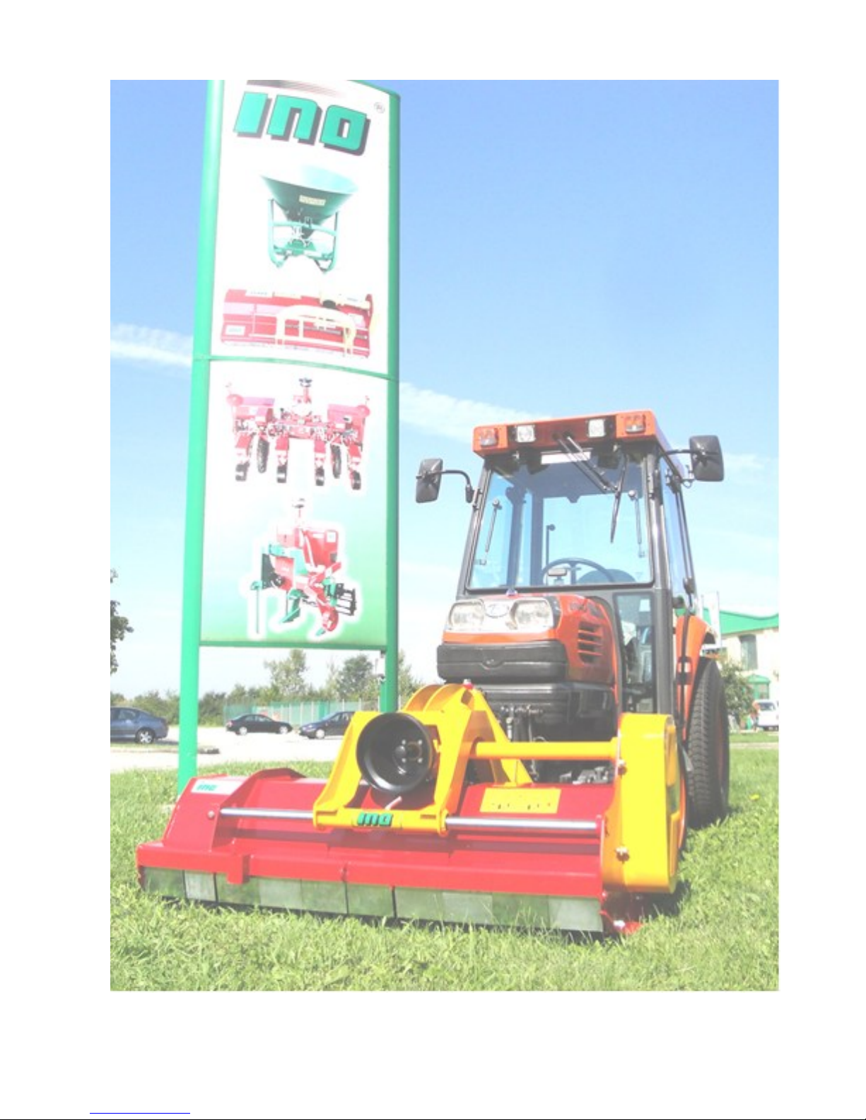
1.1 Purpose of use
Flail mower EURO MINI is universal flail mower, purposed mostly
for mulching grass, branches and vines, smaller bushes and other crop
residues. It is appropriate for all green areas, vineyards and orchards and
also in agriculture. We use it also on other public areas. Its construction
is rigid, designed for intensive use. It is very important also in ecological
way. With mulching we avoid the use of herbicides.
1.2 Warranty
Warranty period for the machine is 24 months.
This machine is in conformity with the following provisions of law:
-Directive Machine 89/392/CEE and following additions:
91/368/CEE, 93/44/CEE and 93/68/CEE
-Regulations UNI EN 292/1 and 292/2 (Machinery Safety)
-Regulation SIST EN 745 (Rotary and flail mowers safety)
A producer can ensure normal operating of the machine
only with use of original spare parts!
INO is not responsible for any damage or injuries, if the
user doesn't consider the rules in this book!
INO is not responsible for any damage or injuries due to
improper use of the machine!
After receiving the machine it is necessary to check that the machine
was not injured during transport and that it is equipped with all basic and
additional equipment ( if ordered). A customer can claim any missing or
damaged part in the period of 8 days after receiving the machine.
Table of contents
Other iNO Lawn Mower manuals


