iNO DOMINATOR User manual


2
CONTENT
1. General information………………………………………………… 4
1.1 Purpose of use…………….………………………………………….. 4
1.2 Warranty……………………………………………………………… 5
1.3 Identification of the machine..……………………………………… 6
2. Technical data…..……………………………………………………. 7
2.1 Noise.. ………………………………………………………………… 7
2.2 Technical specification ……………………………………………… 8
2.3 Optional equipment……………………………………………….… 8
3. Safety….……………………………………………………………… 9
3.1 General safety rules………………………………………………….. 9
3.2 Attachment on the tractor and transport…………………………. 10
3.3 PTO drive……………………..………………………………….…. 10
3.4 Hydraulic system...……………………………………………..…... 11
3.5 Safety rules during use, maintenance and servicing……………... 12
3.6 Warning decals……………………………………………………... 13
3.7 List of guards…..………………………………………………….... 14
4. Description and operating of the machine………………………… 15
5. Transport and attachment of the machine……………………….. 16
5.1 Transport to the customer..………………………………………... 16
5.2 Attachment and detachment from the tractor…………………... 16
5.3 Fitting the PTO shaft………………………..……………………... 17
5.4 Stability of the tractor…………………………………………….. 18
6. Adjustment ……………………………………………………….. 19
6.1 Support roller adjustment………………………………………. 20
6.2 Roller setup…………………….……………………………………… 21
6.3 Offsetting……………………………………………….. 22
6.4 Belt tension adjustment………..…………………………………… 23
7. Operating….….……………………………………………………. 24
8. After the job is done..………………………………………………… 26
8.1 Cleaning…………………………………………………………….. 26
9. Maintenance……………………………………………………….. 27
9.1 Oil control in the gearbox ………..……………………………….. 27
Greasing ……..…………………………………………………….. 28
9.2 Plan of maintenance jobs ……….…………………………………. 29
9.3 Replacement of working tools……………………………………... 29
9.4 At the end of the season …………………………………………… 30
9.5 Demolition when out of order ………………...…………………… 30
10. Trouble shooting …..……………………………………………….. 31

3
Dear Customer!
We are grateful that you decided to buy our product.We would like to
thank you for your trust. We are sure that you won't be disappointed with
your choice. A quality of the material, appropriate technical characteristics
and after sales services go together with your choice. For eventual
questions our stuff is always at your disposal.
We will specially respect your suggestions and observations that can be
of a great help for future development of the machine Through all the past
of our company experiances from the praxis represent a basement of de-
velopment and innovations.
INO Brežice d.o.o.

4
1. General information
This operation and maintenance manual is intented to the operator. It
consists of operating instructions, maintenance part and spare parts list for
the machine.
It is mandatory to follow these instructions in order to prevent events
which could endanger the operator's, other people's and animal's safety,
apart from the correct functioning of the machine. In case of doubt do not
experiment, call INO after-sales service instead, or a specialized INO dealer.
It is mandatory to read these instructions to understand the
operating of the machine!
In the case of re-sale of the machine it is necessary to give
these instructions to the new owner!
A meaning of decals in this book
Very important information!
Technical warning!
Safety warning!

5
Purpose of use
Flail mower DOMINATOR is a heavy duty professional machine, purpo-
sed for use on large agriculture and green areas, for mulching maize and
other crop residues, grass and bushes on green and abandoned areas. This
machine is very rigid and made for use in hard working conditions.
Warranty
Warranty period for the machine is 24 months.
WE DECLARE WITH FULL RESPONSIBILITY THAT THIS TYPE OF THE PRO-
DUCT FULFILLS ALL THE RELEVANT PROVISIONS OF THE FOLLOWING DI-
RECTIVES:
DIRECTIVE MACHINE 2006/42/EC
AND FOLLOWING ADDITIONS:
91/368/CEE, 93/44/CEE, 93/68/CEE
HARMONISED STANDARDS APPLIED IN ORDER TO VERIFY COMPLIANCE
WITH DIRECTIVES:
SIST-EN 292-1, SIST-EN 292-2, SIST EN ISO 4254-12:2012
A producer can ensure normal operating of the machine only
with use of original spare parts!
INO is not responsible for any damage or injuries, if the user
doesn't consider the rules in this book!
INO is not responsible for any damage or injuries due to impro-
per use of the machine!
After receiving the machine it is necessary to check that the machine
has not been injured during transport and that it is equipped with all basic
and additional equipment ( if ordered). A customer can claim any missing
or damaged part in the period of 8 days after receiving the machine.

6
INO does not accept any responsibility in the case of:
•Improper maneuvring the machine,
•Improper maintenance,
•Unauthorized repairing ormodifications on the machine or use
of non-genuine spare parts,
•Non-respecting these rules,
•Overloading of the machine (see Table nr.1 –limited values)
Identification of the machine
Each machine is fitted with an identification plate with the following
data: producer and address, CE sign, name of the machine, type, weight,
identification number and year of production.
Fig. 1
MULCER
DOMINATOR
1093 kg
2019
123
7
2. Technical data
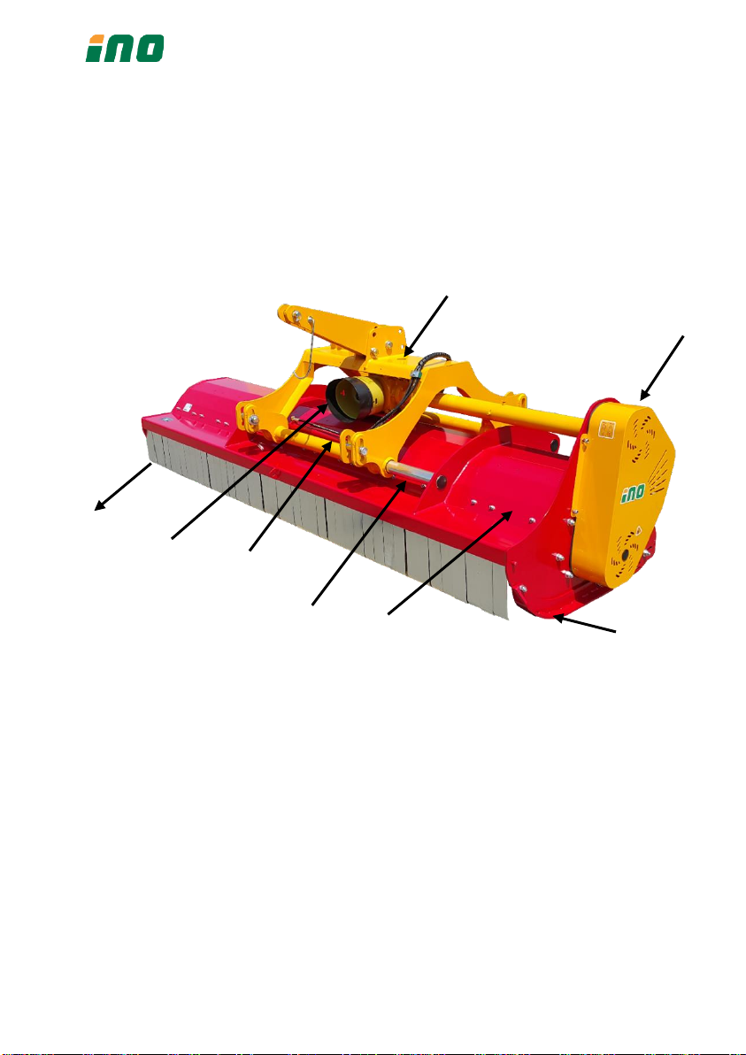
Fig. 2
1. frame
2. gearbox
3. belt drive
4. linkage
5. flaps
6. hydraulic cylinder
7. skids
8. sliding tubes
Noise
The sound level of this machine, as measured at the operator's ear,
ranges from 70 to 90 dB when the rear window of tractor is open. We
recommend the use of ear protectors
1
2
3
1
5
4
7
6
8

8
Optional equipment
According to the working requirements we recommend the following
additional equipment:
•Y-blades
•Double skin
•Reversible gearbox
•Gearbox 540 rpm
•INO VIBRATION CONTROL
Technical specification
Table. 1: Technical data
Type
Unit
DOMINATOR
250
DOMINATOR
270
DOMINATOR
300
Working width
cm
244
277
312
Min.tract.power
HP
65
75
90
Max.tract.power
HP
110
110
130
RPM
min-1
540/1000
540/1000
540/1000
Y blades
nr.
84
96
108
Hammers
nr.
28
32
36
Weight
kg
971
1023
1093
Offsetting
cm
50
50
50
Linkage
cat.
II
II
II
Total width
cm
267
300
333

9
3. Safety
General safety rules
1. Before starting the machine, functionality, road safety and acci-
dent prevention rules must be checked.
2. Together with the operating and maintenance rules for the ma-
chine it is necessary to consider general health and security rules
and warnings.
3. Before starting it is mandatory to know everything regarding the
equipment and operating of the machine. Reading instructions
when operating is too late.
4. Security and warning decals on the machine are very important.
Respect them always.
5. Even when using the machine correctly, stones or other objects
may accindentally fly a long distance. Therefore everybody must
stand out of the danger area. Special attention must be paid when
working near roads or buildings.
6. Use tractor with the cabin.
7. Whenever using public roads, respect traffic rules.
8. Never wear loose or fluttering clothes.
9. Keep the machine clean to avoid fire danger.
10. Before starting check the surrounding area for the likely presence
of children and/or animals.
11. Never carry passengers on the machine.
12. Never overload the machine and the tractor. Use the ballast if ne-
cessary.
13. Start the machine only if all guards of the machine are fit on proper
places .
14. It is forbidden to stand in the range of operating of the machine.
15. Do not enter the working zone of the PTO shaft. It is dangerous to
approach the rotating parts of the machine.
16. Keep a safety distance from drive parts outside the machine (PTO
shaft, hydraulic pipes).
17. Before leaving the tractor with the machine attached disconnect
the tractor, put the machine steadily on the ground (with the

10
hydraulic lift), apply the hand brake and if the ground is steeply
slooping, wedge the tractor.Take out the starting key.
18. Do not enter the zone between the tractor and the machine. It is
strongly forbidden to be in this zone if the tractor is not properly
disconnected, hand brake applied and starting key taken out.
Attachment to the tractor and transport
1. Before attaching the machine or detaching it of the tractor be sure
that hydraulic lift system is in a neutral position.
2. Check that a category of 3-point linkage on the tractor corresponds
to that one on the machine.
3. Be careful! There is a danger of injuries when working near or with
3-point linkage.
4. It is forbidden to be in the zone between the tractor and the ma-
chine while working with the hydraulics.
5. Put the 3-point linkage into the position that makes the moving of
the machine impossible.
6. During transport secure the lever of hydralic lift to avoid any
unplanned moving of the machine.
7. ever leave the tractor cab when the tractor is working.
8. Adjust driving speed to the road conditions.
PTO drive
1. Use only PTO shafts with all guards, as directed by the producer.
2. All guards on PTO shaft must be in good order .
3. Take care that all guards on the PTO shaft are in proper position
during transport or operating. Respect the producer's instructions.
4. The PTO shaft must be assembled or diassambled only with the
engine stopped and the starting key removed.
5. The guards of the PTO shaft must be fixed to the machine and to
the tractor with chains to prevent rotation.
6. Before starting always check that the speed and the rotational di-
rection correspond to those on the machine.

11
7. With some tractors a number of rotations depends on the speed
and a direction of rotating depends on the direction of driving.
Take care about that.
8. Before starting the PTO shaft be sure, that noone is in the danger
area.
9. Never try to start the PTO shaft when the tractor engine is discon-
nected.
10. It is forbidden to be in the zone of drive axle exit, when it is enga-
ged.
11. After the drive is disconnected wait that the drive axle stops to ro-
tate completely. Never approach before it stops.
12. Never carry out maintenance of a machine or tractor while the en-
gine is running. The engine should be switched off and the key re-
moved.
13. If the PTO shaft is damaged, immediately stop with any operating.
Hydraulic system
1. Take care! Hydraulics is under very high pressure.
2. When connecting the pipes on the tractor check that the pressure
is not too low.
3. We recommend that an official service tests the pipes before ope-
rating and than at least ones per year. Damaged or worn outpipes
should be replaced immediately with others of the same specifica-
tion.
4. When checking pipes it is necessary to wear protection clothes and
gloves to avoid injuries.
5. The oil under high pressure may sweep into the skin causing seri-
ous infections. In this case contact a doctor immediately.
6. Before working on the hydraulic system lower the machine, take
pressure out and stop the tractor.
7. Approximate using period of the pipes is 6 years. After that the
pipes should be replaced to avoid any damage.
8. Used oils and greases must be stored and disposed according to
antipollution rules.
9.

12
Safety rules during use, maintenance and servicing
1. Never start or continue to work with the machine if the tractor or
the drive axles are engaged
2. Always remove the starting key after you stopped the tractor.
3. Periodically check that bolts and nuts are tighten properly.
4. When maintaining it is sometimes necessary to lift the machine. It
is mandatory to put under the machine an appropriate support to
avoid falling the machine at eventual damage on hydraulics.
5. Use the gloves and appropriate tools at changing sharp parts of the
machine to avoid injuries.
6. Used oils and greases should be removed according to the rules.
7. Always disconnect electric cables on the tractor before any wel-
ding or other operation when using electricity is necessary.
8. Only original spare parts should be installed

13
Warning decals
1. Always turn off the machine of the tractor and
read the instructions carefully before starting
servicing and/or lubrification operations.
2. Keep at a safety distance from the machine to
avoid the risk of flying objects.
3. Never remove the guards while the parts of
the machine are moving. It can injure the
hands.
4. Keep at a safety distance from the machine to
avoid the risk of injuring the feet.
5. It is forbidden to stand on the machine be-
cause of the risk of fall!
14
List of guards
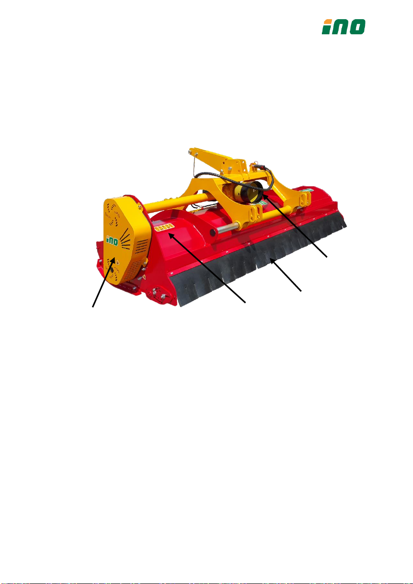
Fig. 3
1. PTO shaft shield PVC
2. belt shield
3. warning decals
4. rubber guard
1
2
3
4
15
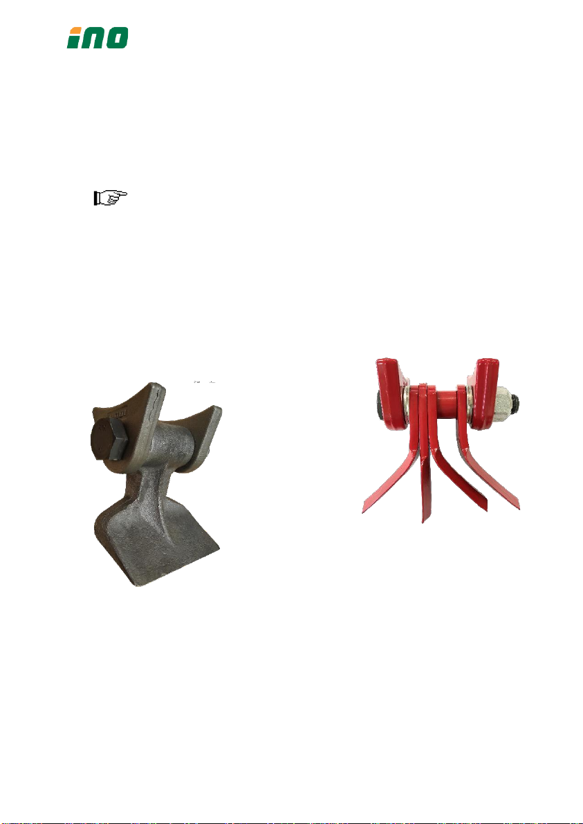
4. Description and operating of the machine
The machine is equipped with hammers on the rotor shaft. Hammers
are used for material with diameter with diameter Ø 6 cm. Optional wor-
king tools Y-blades are used for cutting material with diameter Ø 3
cm.While rotating working tools cut the material and lift it under the top of
the frame. Falling material is again cut several times by rotating hammers.
Maximal thickness of the material depends on the sort and
hardness of the wood. Up-mentioned diameters are valid for
the fresh wood only.
Fig. 4
Fig. 5

16
5. Transport and attachment of the machine
Transport to the customer
Unload the machine with special care to avoid any damage. Check that
all nuts and bolts are fixed and tightened. Specially check the bolts and nuts
for the working blades.
Attachment and detachment from the tractor
Before any operation check:
•That the machine is in good condition,
•That all guards are in proper places and in good condition,
•That working blades are complete and undamaged,
•That all greasing points are greased well and that in gearbox is
enough oil,
•Appropriate tensioned belts,
•That rpm and direction of rotation on the drive axle correspond
to those on the machine.
When you attach the machine to the tractor, bring the tractor lower
lines near the machine, to the points corresponding to the pins. Insert the
pins and secure them with the spring clips. Fit the top link, raise the ma-
chine to a perpendicular position to the ground. Adjust the two tractor
lower linkage stabilizers thus fixing the machine to the tractor in a central
position. Connect the hydraulic cylinders and check if it works.
3-point hitch of the machine must be in a simetrical position
with the tractor.
Top linkage point has two working modes: floating and fixed linkage.
Use floating position whenever working on hilly, uneven terrain to avoid
damaging the machine or linkage. To get floating position just remove the
pin, fixing the top linkage bracket, on the opposite site of the linkage
bracket (see Fig.6).

17
Fig 6
It is mandatory to use floating linkage on hilly or sloping ter-
rain!
Before any change af attachment (front, rear) it is mandatory to
check that rpm and direction of rotation on the drive axle correspond
to those on the machine.
Fitting the PTO shaft
Attach the machine on the tractor. Split the tubes into both parts and
put one part on the tractor and another on the machine. At the machine
laying on the ground, minimum overlapping of the tubes mustn't be less
than 1/3 of total length. Cut too long part of the tube and clean the edges.
Cut on the proper length also the guard as on fig. 13. Measure the length
when the PTO shaft is in horisontal position. Grease before putting them
together.
Too long PTO shaft can seriously damage tractor or flail
mower.
Never put PTO shaft on the tractor without all guards and cha-
ins fitted properly.

18
Fig. 7: Appropriate length of PTO shaft at the machine on the ground
Fig. 8: Appropriate length of the guard when machine is lifted.
Stability of the tractor
At attachment of the machine on the tractor always take care
about allowed weight of the attachment and axle load. First
axle of the tractor should always be loaded with min.20% of
the weight of the tractor itself. This is very important specially
on this machine because of its distance between the tractor
and working part of the machine!
Fig. 9
1/3 shaft

19
6. Adjustment
Working height adjustment
Height of cut depends on working conditions and volume of the mate-
rial. The height of cut can be regulated with the hydraulic system on the
tractor or/and with adjusted rear roller of the machine (Fig. 13). The min.
height of cut should be between 1-3 cm. The machine always run on the
rear roller and not on the skids.
Working tools should never touch the ground. The skids are
only the protection against injures.

20
Support roller adjustment
You can set the roller in two positions depending how you want to dis-
perse the material and working conditions and volume of the material.
Fig. 12
Table of contents
Other iNO Lawn Mower manuals


