iNO MKM User manual

1
INO BREŽICE d.o.o.
8262 Krška vas 34 b, Slovenija
Tel.: ++386 (0) 749 59 233;
Fax: ++ 386 (0) 749 59 151
Internet: www.inobrezice.com
F
FL
LA
AI
IL
L
M
MO
OW
WE
ER
R
M
MK
KM
M
O
OP
PE
ER
RA
AT
TI
IN
NG
G
I
IN
NS
ST
TR
RU
UC
CT
TI
IO
ON
NS
S
S
SP
PA
AR
RE
E
P
PA
AR
RT
TS
S
L
LI
IS
ST
T
I
IT
T
I
IS
S
M
MA
AN
ND
DA
AT
TO
OR
RY
Y
T
TO
O
R
RE
EA
AD
D
A
AN
ND
D
F
FO
OL
LL
LO
OW
W
T
TH
HE
ES
SE
E
I
IN
NS
ST
TR
RU
UC
CT
TI
IO
ON
NS
S
B
BE
EF
FO
OR
RE
E
C
CA
AR
RR
RY
YI
IN
NG
G
O
OU
UT
T
A
AN
NY
Y
O
OP
PE
ER
RA
AT
TI
IO
ON
N!
!

2
CONTENT
1. General information……………………………………………….. 4
Purpose of use………………………………………………………. 5
Warranty...…………………………………………………………. 5
Identification of the machine …………………………………….. 6
2. Technical data …………………………………………………….. 7
Noise ……………………………………………………………….. 7
Technical specification ……………………………………………. 8
Optional equipment……………………………………………….. 9
3. Safety………………………..……………………………………… 10
General safety rules……………………………………………….. 10
Attachment on the tractor and transport.……………………….. 11
PTO drive……………………..………………………………….… 12
Hydraulic system...……………………………………………..….. 13
Safety rules during use……………………………………………. 14
Warning decals…………………………………………………….. 15
List of guards…..…………………………………………………... 16
4. Description and operating of the machine……………………….. 17
5. Transport and attachment of the machine………………………. 18
Transport to the customer.………………………………………... 18
Attachment and detachment from the tractor…………………... 19
Fitting the PTO shaft………………………..…………………….. 20
Stability of the tractor…………………………………………….. 21
6. Adjustment and setting up………………………………………… 22
Regulating the height of cut………………………………………. 22
Belt tension adjustment…………………………………………… 23
7. Operating….…….…………………………………………………. 24
8. After the job done…………………………………………………. 27
Cleaning……………………………………………………………. 28
9. Maintenance.………………………………………………………. 29
Belt tension control………………………………………………... 30
Oil level control……………………………………………………. 31
Control of bolts……………………………………………………. 31
Greasing……………………………………………………………. 32
Plan of maintenance jobs……….………………………………… 34
Replacement of working tools……………………………………. 34
At the end of the season……………………………………….….. 35
Demolition when out of order……………………………………. 35
10. Trouble shooting……………………………………...…..……….. 36
11. Spare parts……………………………..………………….………. 37

3
Dear Customer!
We are glad that you decided to buy our product.
We would like to thank you for your trust. We are sure that you won't be
disappointed with your choice. A quality of the material, appropriate technical
characteristics and after sales services go together with your choice. For
eventual questions our stuff is always at your disposal.
We will specially respect your suggestions and observations that can be of a
great help for future development of the machine Through all the past of our
company experiances from the praxis represent a basement of development and
innovations.
INO d.o.o., General Manager
4
1. General information
This operation and maintenance manual is intented to the operator. It
consists of operating instructions, maintenance part and spare parts list for
the machine.
It is mandatory to follow these instructions in order to prevent events
which could endanger the operator's, other people's and animal's safety,
apart from the correct functioning of the machine. In case of doubt do not
experiment, call INO after-sales service instead, or a specialized INO
dealer.
It is mandatory to read these instructions to understand
the operating of the machine!
In the case of re-sale of the machine it is necessary to give
these instructions to the new owner!
A meaning of decals in this book
Very important information!
Technical warning!
Safety warning!

5
1.1 Purpose of use
Flail mower MKM is purposed mostly for mulching grass, branches
and vines, smaller bushes and other crop residues. It is appropriate for all
green areas, vineyards and orchards. We use it on public areas, for banks
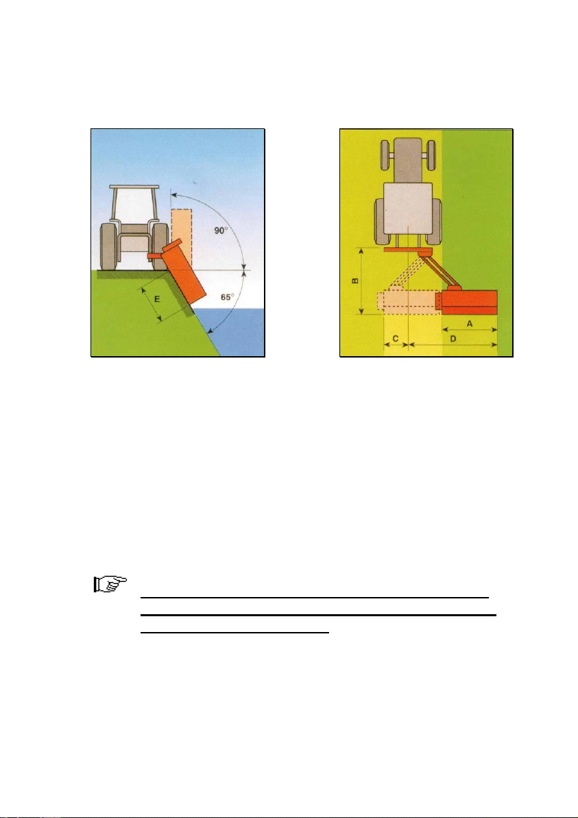
and verges. Its construction is rigid, designed for intensive use, under the
angle +90°/-65°. It is very important also in ecological way. With
mulching we avoid the use of herbicides.
1.2 Warranty
Warranty period for the machine is 24 months.
WE DECLARE WITH FULL RESPONSIBILITY THAT THIS TYPE OF THE PRODUCT
FULFILS ALL THE RELEVANT PROVISIONS OF THE FOLLOWING DIRECTIVES:
DIRECTIVE MACHINE 89/392/CEE
AND FOLLOWING ADDITIONS:
91/368/CEE, 93/44/CEE, 93/68/CEE AND 2006/42/CEE
HARMONISED STANDARDS APPLIED
IN ORDER TO VERIFY COMPLIANCE
WITH DIRECTIVES: SIST-EN 292-1, SIST-EN 292-2, SIST EN 745
A producer can ensure normal operating of the machine
only with use of original spare parts!
INO is not responsible for any damage or injuries, if the
user doesn't consider the rules in this book!
INO is not responsible for any damage or injuries due to
improper use of the machine!
After receiving the machine it is necessary to check that the machine
was not injured during transport and that it is equipped with all basic and
additional equipment ( if ordered). A customer can claim any missing or
damaged part in the period of 8 days after receiving the machine.

6
INO does not accept any responsibility in the case of:
Improper maneuvring the machine,
Improper maintenance,
Unauthorized repairing or modifications on the machine or
use of non-genuine spare parts,
Non-respecting these rules,
Overloading of the machine (see Table nr.1 –limited values)
1.3 Identification of the machine
Each machine is fitted with an identification plate with the following
data: producer and address, CE sign, name of the machine, type, weight,
identification number and year of production.
Fig. 1
MULČER
MKM 190
693 kg
2012
123
7
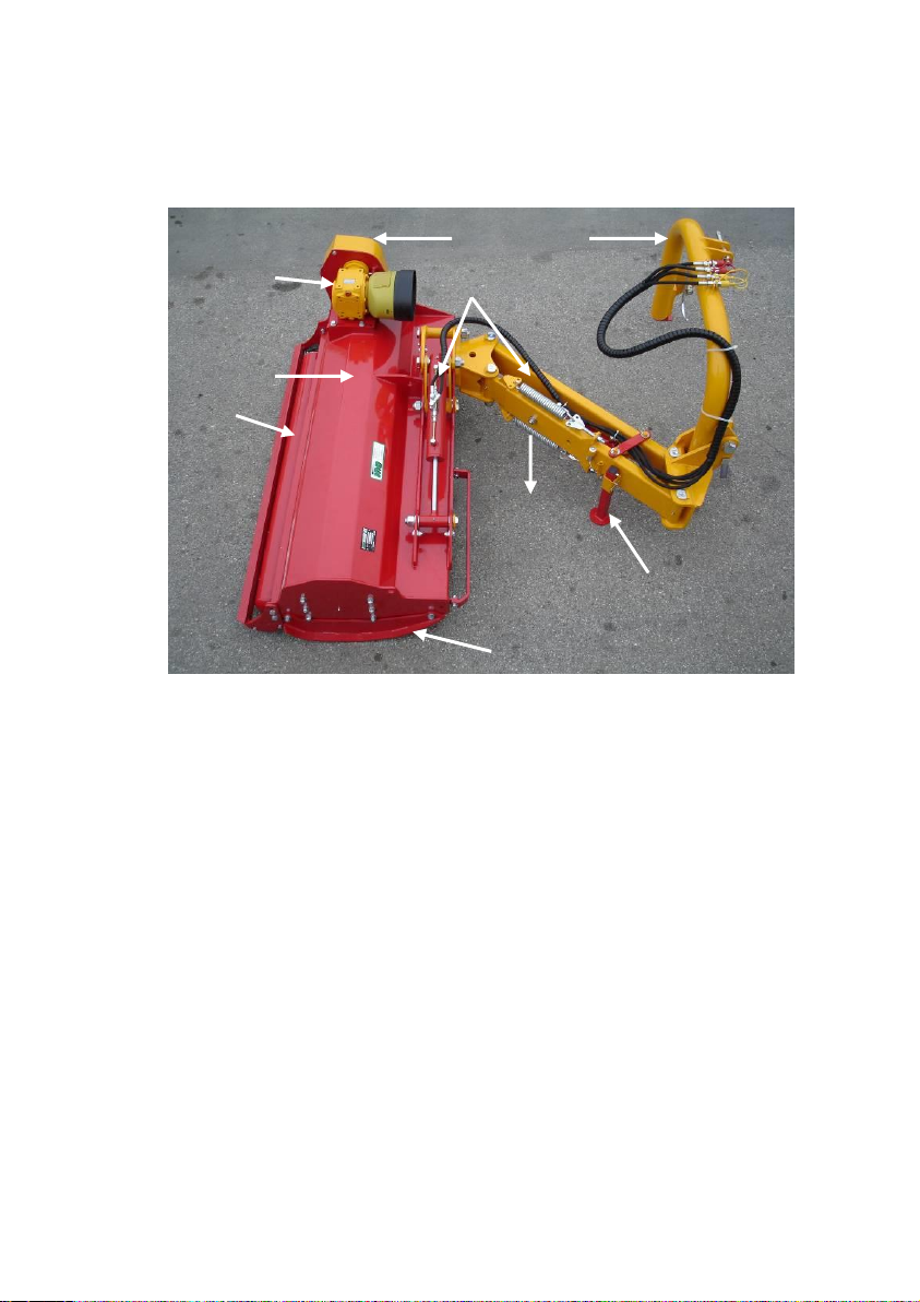
2Technical data
Fig. 2
1. frame
2. gear box
3. belt drive
4. 3-point linkage
5. rear roller
6. support foot
7. skid
8. sliding tubes
9 mower arm
2.1 Noise
The sound level of this machine, as measured at the operator's ear,
ranges from 70 to 90 dB when the rear window of tractor is open. We
recommend the use of ear protectors
4
9
6
7
1
5
3
2
8

8
2.2 Technical specification
Tab. 1: Technical data for MKM
Type
130
160
190
225
245
Working width
cm
132
162
192
227
242
Tractor power
HP
40/70
50/80
70/90
80/100
90/120
Min.tractor weight
kg
1800
2200
2400
2600
2800
Min.tractor width
cm
160
180
200
200
200
drive
rpm
540
540
540
540
540
Weight
kg
522
575
693
748
810
linkage
cat
II
II
II,III
II,III
II,III
Angle
°
+90/-65
+90/-65
+90/-65
+90/-65
+90/-65
Y-bl
nr
32
40
48
56
60
hammer
nr
16
20
24
28
30
width
cm
153
183
213
248
263
height
cm
100
100
100
100
100
Transp.length
cm
165
165
165
165
165
Tab.2: Working width in different positions
MKM
Unit
MKM
130
MKM
160
MKM
190
MKM
225
MKM
245
A
cm
132
162
192
227
242
B
cm
200
200
200
200
200
C
cm
34
37
37
37
37
D
cm
230
260
290
325
345
E
cm
104
134
164
199
219
9
Fig. 3
Fig. 4
2.3 Optional equipment
According to the working conditions we recommend the following
additional quipment:
Y blade (for cutting material till max. 3 cm in diameter)
Hammers (for cutting material till max 5 cm in diameter)
Maximal thickness of the material depends on the sort
and hardness of the wood. Up-mentioned diameters are
valid for the fresh wood only.

10
3. Safety
3.1 General safety rules
1. Before starting, checks on the tractor and the machine must be
carried out as regards: functionality, road safety, accident
prevention rules.
2. Together with the operating and maintenance rules for the
machine it is necessary to consider general health and security
rules and warnings.
3. Before starting it is mandatory to know everything regarding the
equipment and operating of the machine. Reading instructions
among operating is too late.
4. Security and warning decals on the machine are very important.
Respect them always.
5. Even when using the machine correctly, stones or other objects
may be thrown on a long distance. Therefore nobody must stand
within the danger area. Special attention must be paid when
working near roads or buildings.
6. Use tractor with the cabin.
7. Whenever using public roads, respect traffic rules.
8. Never wear loose or fluttering clothes.
9. Keep the machine clean to avoid fire danger.
10. Before starting check the surrounding area for the likely presence
of children and/or animals.

11
11. Never carry passengers on the machine.
12. At connecting the machine on the tractor put both support feet
into the working position (up). After removal put the support feet
into the standing position (down). Take care about the stability of
the machine when it is removed.
13. Never overload the machine and the tractor. Use the ballast if
necessary.
14. Start the machine only if all guards of the machine are fit on
proper places .
15. It is forbidden to stand in the range of operating of the machine.
16. Do not enter the working zone of the PTO shaft. It is dangerous to
approach the rotating parts of the machine.
17. Keep a safety distance from drive parts outside of the machine
(PTO shaft, hydraulic pipes).
18. Before leaving the tractor with the machine attached disconnect
the tractor, put the machine steadily on the ground (with the
hydraulic lift), apply the hand brake and if the ground is steeply
slooping, wedge the tractor.Take out the starting key.
19. Do not enter the zone between the tractor and the machine. It is
strongly forbidden to be in this zone if the tractor is not properly
disconnected, hand brake applied and starting key taken out.
Attachment on the tractor and transport
1. Before attaching the machine on or detaching it of the tractor be
sure that hydraulic lift system is in a neutral position.
2. check that a category of 3-point linkage on the tractor
corresponds to that one on the machine.

12
3. Be careful! There is a danger of injuries when working near or
with 3-point linkage.
4. It is forbidden to be in the zone between the tractor and the
machine while working with the hydraulics.
5. Put the 3-point linkage into the position that moving of the
machine during transport is not possible.
6. During transport secure the lever of hydralic lift to avoid any
unplanned moving the machine.
7. It is mandatory to install a horisontal blockade during transport.
8. Never leave the tractor cab when the tractor is working.
9. Adjust driving speed to the road conditions.
PTO drive
1. Use only PTO shafts with all guards, as directed by the producer.
2. All guards on PTO shaft must be in good order .
3. Take care that all guards on the PTO shaft are in proper position
during transport or operating. Respect the producer's instructions.
4. The PTO shaft must be assembled or diassambled only with the
engine stopped and the starting key removed.
5. The guards of the PTO shaft must be fixed to the machine and to
the tractor with chains, to prevent rotation.
6. Before starting always check that the speed and the rotational
direction correspond to those on the machine.
7. At some tractors a number of rotations depends on the speed and
a direction of rotating depends on the direction of driving. Take
care about that.

13
8. Before starting the PTO shaft be sure, that noone is in the danger
area.
9. Never try to start the PTO shaft when the tractor engine is
disconnected.
10. It is forbidden to be in the zone of drive axle exit, when it is
engaged.
11. After the drive is disconnected wait that the drive axle stops to
rotate completely. Never approach before it stops.
12. Never carry out maintenance of a machine or tractor whilst the
engine is running. The engine should be switched off and the key
removed.
13. If the PTO shaft is damaged, immediately stop with any
operating.
Hydraulic system (optional equipment)
1. Take care! Hydraulics is under very high pressure.
2. At connecting the pipes on the tractor check that the pressure is
not too low.
3. We recommend that an official service tests the pipes before
operating and than at least ones per year. Damaged or worn pipes
should be replaced immediately with others of the same
specification.
4. at checking pipes it is necessary to wear protection clothes and
gloves to avoid injuries.
5. The oil under high pressure may sweep into the skin causing
serious infections. In this case contact a doctor immediately.

14
6. Before working on the hydraulic system lower the machine, take
pressure out and stop the tractor.
7. Approximate using period of the pipes is 6 years. After that the
pipes should be replaced to avoid any damage.
8. Used oils and greases must be stored and disposed of according to
antipollution rules.
Safety rules during use
1. Never start or continue to work with the machine if the tractor or
the drive axle are engaged
2. Always remove the starting key after you stopped the tractor.
3. Periodically check that bolts and nuts are tighten properly.
4. At maintaining it is sometimes necessary to lift the machine. It is
mandatory to put under the machine an appropriate support to
avoid falling the machine at eventual damage on hydraulics.
5. Use the gloves and appropriate tools at changing sharp parts of
the machine to avoid injuries.
6. Used oils and greases should be removed according to the rules.
7. Always disconnect electric cables on the tractor before any
welding or other operation when using electricity is necessary.
8. Only original spare parts should be installed.

15
Warning decals
1. Always take off previously the machine of
the tractor and read the instructions carefully
before starting servicing and or lubrification
operations.
2. Keep at a safety distance from the machine to
avoid the risk of projection of objects.
3. Never remove the guards while the parts of
the machine are moving. It is dangerous to
injure the hands.
4. Keep at a safety distance from the machine to
avoid the risk of cutting the feet.
5. It is forbidden to mount on the machine
because of the risk of fall.

16
List of guards
Fig.5
1. PTO shaft shield
2. belt shield
3. warning decals
4. Side guard
5. flaps
6. horisontal blockade
7. vertical hydraul. blockade
8. frame guard
9. mechanic breakaway
10. floating
1
5
2
4
3
6
4
7
8
9
7
10
17
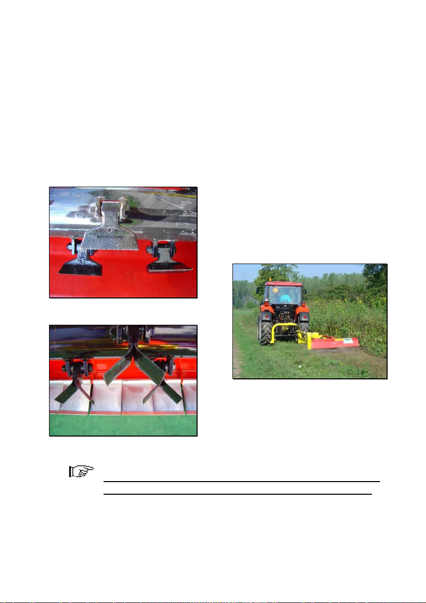
4. Description and operating of the machine
The machine is equipped with hammers (Fig.6) on the rotor shaft or
with y-blades (Fig.7) as an option. Hammers are appropriate for more
hard work, for material with diameter till 5 cm. Y-blades are used for
material with diameter max. 3 cm. While rotating working tools cut the
material and lift it under the top of the frame. Falling material is again cut
several times by rotating hammers (or Y-blades).
Fig.6
Fig.7
Fig.8
Operator manuals are made for all types of the machine.
All special details are described for each type separately.

18
Fig. 9
Fig. 10
5. Transport and attachment of the machine
Transport to the customer
Unload the machine with special care to avoid any damage. For
unloading use special holes on the frame (Fig.11). Check that all nuts and
bolts are fixed and tightened. Specially check the bolts and nuts for the
working blades and on connection arm-frame (Fig.11/1)
Fig.11
According to the dimensions of the machine and different possibilities
of the transport, the machine can be sent split assembled on the pallet or
in the box.
+90°
-65°
1

19
5.2. Attachment and detachment from the tractor
Before any operation check:
That the machine is in good condition,
That all guards are on proper places and in good condition,
That working blades are complete and undamaged,
That all greasing points are greased well and that in gearbox
is oil enough,
Appropriate tensioned belts,
That rpm and direction of rotation on the drive axle
correspond to those on the machine.
To attack the machine to the tractor, bring the tractor lower lines near
the machine, to the points corresponding to the pins. Insert the pins and
secure them with the spring clips. Fit the top link, raise the machine to a
perpendicular position with the ground. Adjust the two tractor lower
linkage stabilizers thus fixing the machine to the tractor in a central
position. Connect the hydraulic cylinders and check if it works.
Before testing of hydraulic system move away blockade
for horisontal movement.
Before transport put on the blockade for horisontal movement. MKM
130,160 and 190 transport in the horisontal position. MKM 225 is
transported in a vertical position because of its total width (Fig 13/1).
Vertical transport position is secured with vertical hydraulic blockade.
Fig. 12
Fig. 13

20
It is mandatory to put on a horisontal blockade during
transport.
3-point hitch of the machine must be in a simetrical
position with the tractor.
At connecting hydraulic pipes first split both parts of
hydraulic connecting ends for each hydraulic cylinder and
properly connect with those on the tractor.
At the machine attached put both support feet into a
transport position.
5.3 Fitting the PTO shaft
Attack the machine on the tractor. Split the tubes into both parts and
put one part on the tractor and another on the machine. At the machine
laying on the ground, minimum overlapping of the tubes mustn't be less
than 1/3 of total length. Cut too long part of the tube and clean the edges.
Cut on the proper length also the guard as on fig. 15. Measure the length
when the PTO shaft is in horisontal position. Grease before putting them
together.
Too long PTO shaft can seriously damage tractor or flail
mower.
Table of contents
Other iNO Lawn Mower manuals


