Inovance MD38CAN2 User manual

User Guide
MD38CAN2 (CANopen) Card
Optional Part for the MD Series Modular Vector AC Drive
MD38CAN2 (CANopen) Card User Guide
Copyright Shenzhen Inovance Technology Co., Ltd.
Shenzhen Inovance Technology Co., Ltd.
Add.: Building E, Hongwei Industry Park, Liuxian Road, Baocheng No. 70 Zone, Bao’an District, Shenzhen
Tel: +86-755-2979 9595
Fax: +86-755-2961 9897
Service Hotline: 400-777-1260
http: //www.inovance.com
Suzhou Inovance Technology Co., Ltd.
Add.: No. 16 Youxiang Road, Yuexi Town, Wuzhong District, Suzhou 215104, P.R. China
Tel: +86-512-6637 6666
Fax: +86-512-6285 6720
Service Hotline: 400-777-1260
http: //www.inovance.com
Min
A00
Data code 19010927
User Guide

Contents
1 Overview .................................................................................................................................. 1
2 Installation and Setting........................................................................................................... 2
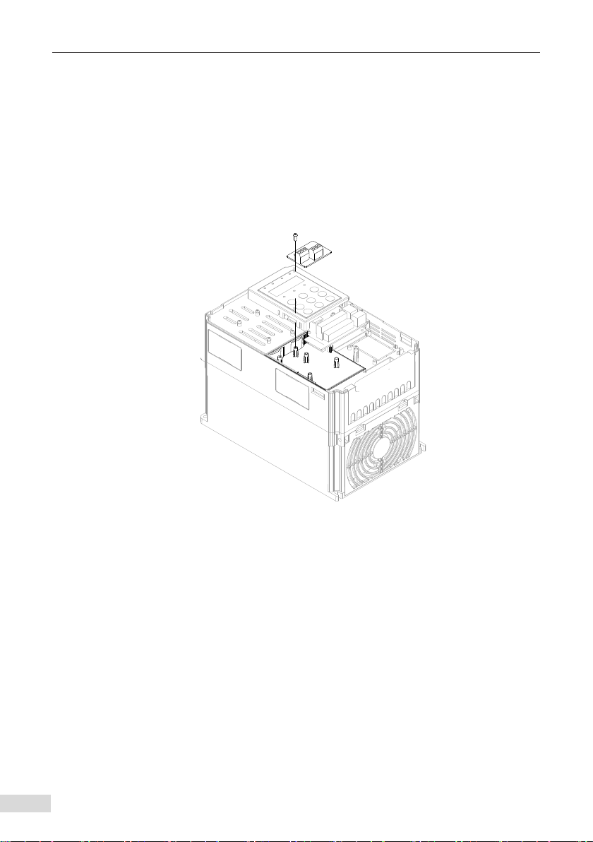
2.1 Installation of MD380CAN2 ........................................................................................... 2
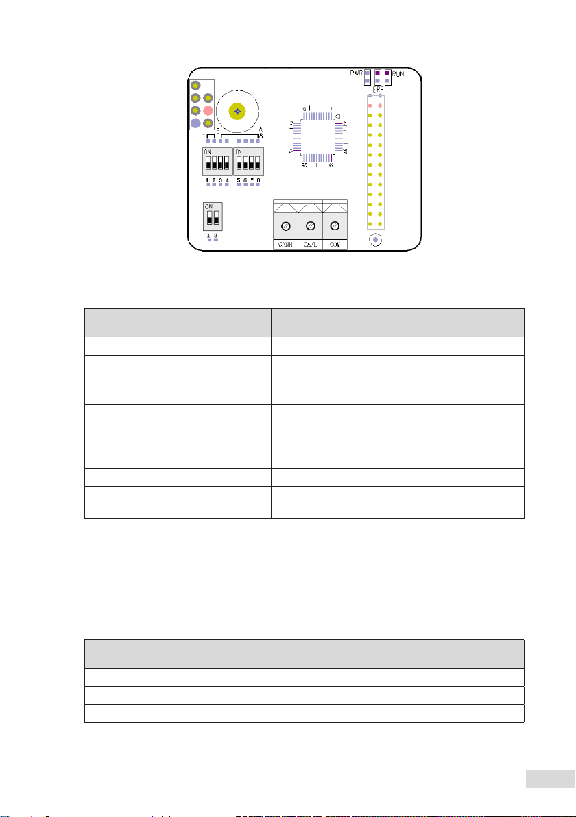
2.2 Hardware Layout ........................................................................................................... 2
2.3 Interface Description ..................................................................................................... 3
3 Protocol Description of the MD38CAN2................................................................................. 7
3.1 Software Feature ........................................................................................................... 7
3.2 COB-ID ............................................................................................................................ 7
3.3 Parameter Operation of AC Drive.................................................................................. 8
3.4 SDO Read-Write Operations........................................................................................ 10
3.5 PDO AC Drive Operation.............................................................................................. 13
4 Parameters Related to CANopen Communication ............................................................. 15
4.1 CANopen Card Enabling.............................................................................................. 15
4.2 Parameters Related to Communication Control....................................................... 15
4.3 Parameters Related to Communication Monitoring................................................. 16
4.4 Emergency Message and AC Drive Fault Description................................................ 19
5 Simple Diagnosis................................................................................................................... 21
5.1 Brief Introduction ........................................................................................................ 21
5.2 Diagnosis...................................................................................................................... 21
5.3 Troubleshooting .......................................................................................................... 21
6 Overview of the CANopen Protocol ..................................................................................... 22
6.1 Brief Introduction ........................................................................................................ 22
6.2 Object Dictionary......................................................................................................... 22
6.3 Common Communication Objects............................................................................. 23
7 Format Description of CANopen Message........................................................................... 24
7.1 NMT Module Control Message.................................................................................... 24
7.2 NodeGuarding Message .............................................................................................. 24
7.3 Heartbeat Message...................................................................................................... 25
Revision History ....................................................................................................................... 26
Warranty Agreement................................................................................................................ 27

1 Overview
- 1 -
1 Overview
Thank you for purchasing Inovance's MD38CAN2 (CANopen) card, the eld bus adapter
for the MD series AC drives.
The MD38CAN2 (CANopen) card is a communication extension card specialized for CAN
communication of the MD series AC drives. It enables the AC drive to access the high-
speed CAN communication network and implements control of the eld bus.
CANopen is a universal eld bus standard and devices that support this protocol can
access the CANopen network.
Before using the product, read this user guide thoroughly.

2 Installation and Setting
- 2 -
2 Installation and Setting
2.1 Installation of MD380CAN2
The MD38CAN2 card is installed inside Inovance's AC drive. Before the installation,
power o the AC drive, wait about 10 minutes until the charging indicator on the AC
drive becomes OFF, and insert the card in the position shown in the following gure.
Then, x the card with screws.
Note that the MD38CAN2 card cannot be inserted at power-on.
Figure 2-1 Installation of the MD38CAN2
2.2 Hardware Layout
The following gure shows the hardware layout of the MD380CAN2. CN1 is the CAN bus
communication interface; DIP switch S1 is used to congure the CAN bus termination
resistor; DIP switches S2 and S3 are used to set the baud rate and address for CAN
communication; the three LED indicators indicate the running state; SW1 is the factory
test interface, and do not connect it.

2 Installation and Setting
- 3 -
CN1
J2
SW1
3
2
1
S2 S3 J1
LED
H
S1
Figure 2-2 Hardware layout of the MD38CAN2
Mark Hardware Name Function Description
SW1 SW1 pin header It is used for the factory test. Do not connect it.
S2/S3 DIP switch It is used to set the baud rate and address for CAN
communication.
S1 Termination resistor setting It is used to set the termination resistor.
J1 Interface for connecting AC
drive It is used to connect the card to the AC drive.
HScrew xing hole It is used to x the card with the M3*8 self-taping
screw.
CN1 Wiring terminal It is the CANopen bus wiring terminal.
LED State indicator The three indicators are used to indicate the
running state.
2.3 Interface Description
1) Communication interface
Terminal CN1 is used to connect the CAN bus. It includes three interfaces, as described
in Table 2.1.
Table 2-1 Interface description of CN1
No. Mark Description
1 CANH Connect positive of the CAN bus.
2 CANL Connect negative of the CAN bus.
3 CGND Connect the shield of the CAN bus.

2 Installation and Setting
- 4 -
2) CAN bus connection
The following gure shows the CAN bus connection. The shielded twisted pairs are
recommended for CAN bus connection. The two sides of the bus are respectively
connected with two 120-Ω terminal matching resistors to prevent signal reection.
Single-point grounding is generally used for the shield.
120 Ω
* Built-in jumper
can be enabled on
the CANlink card.
*
CANL CANH
CANH
Four-core STP
CGND
Avoid sharing the common
ground between the grounding
cable and large-power devices.
Do not remove too much of the shielding layer.
CANL CANH
CGND
Servo drive
CANL
120 Ω
* Built-in jumper can
be enabled on the
CANlink card.
*
+24V
PLC with CAN card
Slave station
CANL CANH
CGND +24V
PLC with CAN card or remote
extension module
24 V power
+-
Master station
CANL CANH
CGND
AC drive with CAN card
Slave station Slave station
[Note 1] [Note 2]
[Note 1] Select a CANlink interface card according to the PLC type.
[Note 2] Select a CANlink interface card according to the AC drive type.
Figure 2-3 CAN bus connection
NOTE
◆Inovance's PLC and MDCAN2 are equipped with built-in resistors, which
can be enabled by the DIP switch.
3) CAN bus transmission distance
The CANopen bus transmission distance is directly related to the baud rate and
communication cable. The following table describes the relationship between the
maximum bus length and the baud rate.
Table 2-2 Relationship between the bus length and the baud rate
Baud Rate (bps) 1 M 500 K 250 K 125 K
Bus Length (m) 30 80 150 150
4) DIP switch
DIP switch S1 of MD38CAN2 composes a 2-digit DIP switch for setting the CAN bus
termination resistor. It is recommended that the termination resistor be used at two
sides of the network topology structure. The switch on the ON position indicates 1, and
indicates 0 otherwise.
Table 2-3 Setting the termination resistor for MD38CAN2
DIP Switch No. Termination Resistor
1 2
0 0 Disconnected
1 1 Connected

2 Installation and Setting
- 5 -
The DIP switches S2 and S3 compose an 8-digit DIP switch for setting the baud rate and
device address for CAN bus communication. The following gure shows the numbering
of DIP switches. Switches 1 and 2 are used to set the baud rate, and switches 3 to 8 are
used to set the CANopen device addresses. The switch on the ON position indicates 1,
and indicates 0 otherwise.
1 2 3 4 5 6 87
Baud rate CANopen device address
Figure 2-4 Numbering of MD38CAN2 DIP switches
■Baud rate
The following table describes the relationship between the DIP switch states and the
baud rates.
Table 2-4 Setting the baud rate for MD38CAN2
DIP Switch No. Baud Rate
1 2
0 0 125 Kbps
0 1 250 Kbps
1 0 500 Kbps
1 1 1 Mbps
■CANopen device address
MD38CAN2 provides six switches for setting the CANopen device addresses. Switch 3 is
the highest bit, and switch 8 is the lowest bit. Switches 3 to 8 correspond to b5 to b0 of a
16-bit binary integer. The address range to be set is 1–63, as listed in the following table.
Address 0 is reserved and cannot be used. If you set address 0, MD38CAN2 will not work.
Table 2-5 Addresses set by the DIP switches of the MD38CAN2
DIP Switch No. Address
3 4 5 6 7 8
0 0 0 0 0 0 Reserved
0 0 0 0 0 1 1
0 0 0 0 1 0 2
0 0 0 0 1 1 3
…… …
1 1 1 1 1 1 63

2 Installation and Setting
- 6 -
5) State indicators
Table 2-6 Description of MD38CAN2 state indicators
Indicator State Description
PWR
(red)
ON Power-on normal
OFF Power-on abnormal (check whether the installation is
correct)
ERR
(red)
ON Internal AC drive communication timeout
Blinking quickly CANopen address setting incorrect
Blinking twice CANopen emergency message indicating AC drive fault
RUN
(green)
ON CANopen "Operational"
Blinking CANopen "Pre-Operational"
OFF CANopen "Stopped"

3 Protocol Description of the MD38CAN2
- 7 -
3 Protocol Description of the MD38CAN2
3.1 Software Feature
MD38CAN2 supports ve protocols, described as follows:
■NodeGuarding: The master can query the device state with this function.
■Heartbeat: The slave reports its current state periodically to the master.
■Service data object (SDO): Only expedited transfer is supported. Two bytes of a
parameter is transferred each time.
■Three transmit process data objects (TPDOs) and three receive process data objects
(RPDOs)
■Emergency (EMCY) objects
3.2 COB-ID
CANopen provides many types of communication objects (COBs), each having dierent
features (for details, see the description of the CANopen standard protocol). Dierent
communication objects are used based on the actual application scenarios. MD38CAN2
adopts the pre-dened communication object identiers (COB-IDs), as follows:
1) Network management (NMT) object: 0x000
2) Synchronization (SYNC) object: 0x080
3) SDO:
■Transmit SDO: 0x600+Node-Id
■Receive SDO: 0x580+Node-Id
4) PDO:
■RPDO1: 0x200+Node-Id
■RPDO2: 0x300+Node-Id
■RPDO3: 0x400+Node-Id
■TPDO1: 0x180+Node-Id
■TPDO2: 0x280+Node-Id
■TPDO3: 0x380+Node-Id
5) EMCY object: 0x80+Node-Id
■Node-Id: Indicates the device ID (node address), and it is set by the DIP switch.
■COB-ID is xedly allocated and cannot be changed.

3 Protocol Description of the MD38CAN2
- 8 -
3.3 Parameter Operation of AC Drive
1) AC drive parameter mapping
■AC drive parameter address
The AC drive parameter addresses are classied into parameter addresses and non-
parameter addresses. For details, see the related description in the section of the
Modbus communication protocol in the MD380 Series High-Performance AC Drive User
Manual.
■Mapping description
The AC drive parameter addresses map to the range of 0x2000 to 0x20FF. The object
dictionary subindex can be obtained by adding one to the parameter number. For
example, if the AC drive parameter is F0-03, the object dictionary index is 0x20F0, and
the subindex is 0x04.
■Mapping description of AC drive parameters
The MD380 parameters are divided into three large groups, groups F0 to FF, groups A0
to AF, and groups U0 to UF.
The following table lists the mapping addresses at the read parameter operation.
Parameter Group CANopen Address Index
F0 to FF 0x20F0 to 0x20FF
A0 to AF 0x20A0 to 0x20AF
U0 to UF 0x2070 to 0x207F
The following table lists the mapping addresses at the read EEPROM operation.
Parameter Group CANopen Address Index
F0 to FF 0x20F0 to 0x20FF
A0 to AF 0x20A0 to 0x20AF
The following table lists the mapping addresses at the read RAM operation.
Parameter Group CANopen Address Index
F0 to FF 0x2000 to 0x200F
A0 to AF 0x2040 to 0x204F
You can obtain the CANopen subindex by adding one to the parameter index.
Parameter Group Index CANopen Subindex
0x0 to 0xFE 0x1 to 0xFF
Take the parameter F0-17 (Acceleration time 1) as an example.

3 Protocol Description of the MD38CAN2
- 9 -
■When the operation is F0-17 reading, the object dictionary index is 0x20F0, and the
subindex is 0x12.
■When the operation is F0-17 reading and writing to EEPROM, the object dictionary
index is 0x20F0, and the subindex is 0x12.
■When the operation is F0-17 reading and writing only to RAM, the object dictionary
index is 0x2000, and the subindex is 0x12.
NOTE
◆Motor auto-tuning cannot be implemented by changing the parameter
values by means of communication.
◆The AC drive parameters are stored in the EEPROM. They can be read
repeatedly but cannot be rewritten many times. Pay attention to the
parameter rewrite command. The PLC programs cannot be driven
unconditionally to prevent cyclic communication write operation which
may damage the storage of the AC drive.
◆If parameters need to be rewritten repeatedly, the mapping addresses
of the parameters at the read RAM operation can be used. For example,
repeated rewriting of the RAM mapping address 0x2002 for F0-02 is
allowed. However, the EEPROM mapping address 0x20F2 cannot be
rewritten repeatedly.
2) AC Drive Operation Example (SDO)
Set the CANopen address of the AC drive to 0x06.
■Read the AC drive command source.
To read the parameter F0-02 of the AC drive, the master sends a CANopen message, as
described in the following table.
Table 3-1 Master sending a message to read F0-02
Message Identier (Hex) RTR Data (Hex)
0x606 040 F0 20 03 00 00 00 00
The AC drive returns a CANopen response message, as described in the following
table. The value of F0-02 is 0x0002, indicating that the current command source is
communication control.
Table 3-2 AC drive's response to F0-02 reading
Message Identier (Hex) RTR Data (Hex)
0x586 0 4B F0 20 03 02 00 00 00
■Set the command source to operating panel control.
To set the command source to operating panel control, the AC drive parameter F0-
02 must be written to 0. The master sends a CANopen message, as described in the
following table.

3 Protocol Description of the MD38CAN2
- 10 -
Table 3-3 Master sending a message to write F0-02
Message Identier (Hex) RTR Data (Hex)
0x606 02B F0 20 03 00 00 00 00
The AC drive returns a CANopen response message, as described in the following
table. The value of F0-02 is written to 0, and the current command source is changed to
operation panel control.
Table 3-4 AC drive's response to F0-02 writing
Message Identier (Hex) RTR Data (Hex)
0x586 060 F0 20 03 00 00 00 00
3.4 SDO Read-Write Operations
1) SDO Read AC Drive Operation
The CANopen SDO is used to perform the read operation on the AC drive. The data
format of the SDO sent by the server is described in the following table.
CAN CANopen Data Description
11-bit ID 0x600+Node-ID Node-ID (device address) set by the DIP
switch
RTR 0Remote frame ag "0"
DATA0 Command code (0x40) 0x40 read command
DATA1 Low byte of index Parameter group (F0 "0xF0")
DATA2 High byte of index Mapping address (see the description in
section 4.3.1)
DATA3 Subindex Parameter number + 1 ("0x03")
DATA4 Data 1 Reserved "0"
DATA5 Data 2 Reserved "0"
DATA6 Data 3 Reserved "0"
DATA7 Data 4 Reserved "0"
The data format of the SDO returned by the client is described in the following table.
If the operation is successful, the return value for the command code is 0x4B, with the
index unchanged; the return value of data 4 and 5 is the read data, and that of data 6
and 7 is 0.
If the operation fails, the return value for the command code is 0x80, with the index
unchanged; the return value of data 4 to 7 is the SDO failure error code (for details about
the error code, see the description of the CANopen protocol).

3 Protocol Description of the MD38CAN2
- 11 -
Table 3-5 SDO returned for reading operation
CAN CANopen Data Description
11-bit ID 0x580+Node-ID Node-ID (device address) set by the DIP switch
DATA0 Return of the
command code Success: 0x4B, error: 0x80
DATA1 Low byte of index Parameter group (F0 "0xF0")
DATA2 High byte of index Mapping address (see the description in section 4.3.1)
DATA3 Subindex Parameter number +1 ("0x03")
DATA4 Data 1 Low byte of data
DATA5 Data 2 High byte of data
DATA6 Data 3 Success: 0
Error: SDO failure error code
(refer to the CANopen protocol)
DATA7 Data 4
2) SDO Write AC Drive Operation
The CANopen SDO is used to perform the write operation on the AC drive. The data
format of the SDO sent by the server is described in the following table.
Table 3-6 SDO sending for write operation
CAN CANopen Data Description
11-bit ID 0x600+Node-ID Node-ID (device address) set by the DIP switch
RTR 0Remote frame ag "0"
DATA0 Command code 0x2B
DATA1 Low byte of index Parameter group (F0 "0xF0")
DATA2 High byte of index Mapping address (see the description in section 4.3.1)
DATA3 Subindex Parameter number + 1 ("0x03")
DATA4 Data 1 Low byte of data
DATA5 Data 2 High byte of data
DATA6 Data 3 Reserved "0"
DATA7 Data 4 Reserved "0"
The data format of the SDO returned by the client is described in the following table.
If the operation is successful, the return value for the command code is 0x60, with the
index unchanged; the return data of data 4 to 7 is 0.
If the operation fails, the return value for the command code is 0x80, with the index
unchanged; the return data of data 4 to 7 is the SDO failure error code (for details about
the error code, see the description of the CANopen protocol).

3 Protocol Description of the MD38CAN2
- 12 -
Table 3-7 Table 3-8 SDO returned for write operation
CAN CANopen Data Description
11-bit ID 0x580+Node-ID Node-ID (device address) set by the DIP switch
RTR 0Remote frame ag "0"
DATA0 Return of the
command code Success: 0x60, error: 0x80
DATA1 Low byte of index Parameter group (F0 "0xF0")
DATA2 High byte of index Mapping address (see the description in section 4.3.1)
DATA3 Subindex Parameter number + 1 ("0x03")
DATA4 Data 1
Success: 0
Error: SDO failure error code
(refer to the CANopen protocol)
DATA5 Data 2
DATA6 Data 3
DATA7 Data 4
3) SDO failure error code
Error Code Description Error Code Description
0x05040000 SDO access timeout 0x06070010 Data type not matched, service
parameter length not matched
0x06010000 Object access not
supported 0x06090011 Subindex not exist
0x06010001 Reading write-only object 0x06090030 Parameter range exceeded for the
write operation
0x06010002 Writing read-only object 0x08000022[1]
Data failed to be transferred or
stored to the application due to
current device status
0x06020000 Object dictionary not exist 0x08000000 General error
[1] This error code is returned when the AC drive is operated to map the object dictionary
parameter, parameters and parameter addresses cannot be changed during AC drive running,
and read-only parameters are written.

3 Protocol Description of the MD38CAN2
- 13 -
3.5 PDO AC Drive Operation
1) RPDO AC Drive Operation
Three RPDOs are supported, namely, RPDO1, RPDO2, and RPDO3. The following table
describes the PDO mapping. For more details, see the MD380CANopen.eds le.
Table 3-8 RPDO mapping
RPDO Name Description
RPDO1
FE-00 AC drive control command
FE-01 AC drive set frequency
FE-02
FE-03
RPDO2
FE-04
FE-05
FE-06
FE-07
RPDO3
FE-08
FE-09
FE-10
FE-11
Drivecom: AC drive control command (The command source is communication control,
that is, F0-02 is set to 2.)
0001: Forward RUN
0002: Reverse RUN
0003: Forward jog
0004: Reverse jog
0005: Coast to stop
0006: Decelerate to stop
0007: Fault reset
Frequency: AC drive set frequency (The frequency source is communication setting, that
is, F0-03 is set to 9. The frequency unit is 0.01 Hz.)
2) TPDO AC Drive Operation
Three TPDOs are supported, namely, TPDO1, TPDO2, and TPDO3. The following table
describes the PDO mapping. For more details, see the MD380CANopen.eds le.

3 Protocol Description of the MD38CAN2
- 14 -
Table 3-9 RPDO mapping
TPDO Name Description
TPDO1
FE-20 AC drive running state (xed mapping)
FE-21 AC drive running frequency
FE-22
FE-23
TPDO2
FE-24
FE-25
FE-26
FE-27
TPDO3
FE-28
FE-29
FE-30
FE-31
Drive Status: AC drive running state
Bit0: 0 indicating stop, and 1 indicating running
Bit1: 0 indicating forward RUN, and 1 indicating reverse RUN
Bit2: 0 indicating no fault, and 1 indicating AC drive fault
Bit3: 0 indicating not reached, and 1 indicating set frequency reached
Bit4 to bit7: Reserved
Bit8 to Bit15: AC drive error code
Frequency: AC drive running frequency (The frequency unit is 0.01 Hz.)
Note: PDO mapping must contain the command word and status word.

4 Parameters Related to CANopen Communication
- 15 -
4 Parameters Related to CANopen Communication
4.1 CANopen Card Enabling
To enable the CANopen card, set the parameters as described in the following table.
Table 4-1 Related parameters for CANopen card enabling
Parameter Parameter Name Setting Range
F0-28 Communication
extension card type
0: 485 communication card
1: Communication extension card (CANopen or DP)
F0-02 Command source
selection
0: Operation panel control
1: Terminal control
2: Communication control
F0-03 Main frequency source
X selection 9: Communication setting
F0-04 Auxiliary frequency
source Y selection Same as F0-03 (Main frequency source X selection)
4.2 Parameters Related to Communication Control
The following table lists the major parameters related to communication control. The
main index address is 0x2073. For details on other parameters, see the MD380 Series
High-Performance AC Drive User Manual.
Table 4-2 Major parameters related to communication control
Parameter Parameter Name CANopen
Subindex Setting Range
U3-16 Frequency setting 0x11
-Maximum frequency to
+Maximum frequency
0.01 Hz

4 Parameters Related to CANopen Communication
- 16 -
Parameter Parameter Name CANopen
Subindex Setting Range
U3-17 Control command 0x12
0001: Forward RUN
0002: Reverse RUN
0003: Forward jog
0004: Reverse jog
0005: Coast to stop
0006: Decelerate to stop
0007: Fault reset
U3-18 DO control 0x13
Bit0: DO1 output control
Bit1: DO2 output control
Bit2: Relay1 output control
Bit3: Relay2 output control
Bit4: FMR output control
Bit5: VDO1
Bit6: VDO2
Bit7: VDO3
Bit8: VDO4
Bit9: VDO5
U3-19 AO1 control 0x14 0 to 7FFF indicates 0% to 100%.
U320 AO2 control 0x15 0 to 7FFF indicates 0% to 100%.
U3-21 FMP control 0x166 0 to 7FFF indicates 0% to 100%.
U3-22 Reserved Reserved Users cannot write this parameter.
U3-23 Rotation speed
control 0x18 Signed value.
1 rpm
4.3 Parameters Related to Communication Monitoring
The following table lists the major parameters related to communication monitoring.
For details on other parameters, see the MD380 Series High-Performance AC Drive User
Manual.
Table 4-3 Major parameters related to communication monitoring
Parameter Parameter Name CANopen
Subindex Unit
U0-00 Running frequency (Hz) 0x01 0.01 Hz
U0-01 Set frequency (Hz) 0x02 0.01 Hz
U0-02 Bus voltage (V) 0x03 0.1 V
U0-03 Output voltage (V) 0x04 1 V
U0-04 Output current (A) 0x05 0.01 A

4 Parameters Related to CANopen Communication
- 17 -
Parameter Parameter Name CANopen
Subindex Unit
U0-05 Output power (kW) 0x06 0.1 kW
U0-06 Output torque (%) 0x07 0.1%
U0-07 DI state 0x08 1
U0-08 DO state 0x09 1
U0-09 AI1 voltage (V) 0x0A 0.01 V
U0-10 AI2 voltage (V) 0x0B 0.01 V
U0-11 AI3 voltage (V) 0x0C 0.01 V
U0-12 Count value 0x0D 1
U0-13 Length value 0x0E 1
U0-14 Load speed display 0x0F 1
U0-15 PID setting 0x10 1
U0-16 PID feedback 0x11 1
U0-17 PLC stage 0x12 1
U0-18 Pulse input frequency (Hz) 0x13 0.01 kHz
U0-19 Feedback speed (Hz) 0x14 0.01 Hz
U0-20 Remaining running time 0x15 0.1 min
U0-21 AI1 voltage before correction 0x16 0.001 V
U0-22 AI2 voltage before correction 0x17 0.001 V
U0-23 AI3 voltage before correction 0x18 0.001 V
U0-24 Linear speed 0x19 1 m/min
U0-25 Current power-on time 0x1A 1 min
U0-26 Current running time 0x1B 0.1 min
U0-27 Pulse input frequency 0x1C 1 Hz
U0-28 Communication setting value 0x1D 0.01%
U0-29 Encoder feedback speed 0x1E 0.01 Hz
U0-30 Main frequency X display 0x1F 0.01 Hz
U0-31 Auxiliary frequency Y display 0x20 0.01 Hz
U0-32 Viewing any memory address
value 0x21 1
U0-33 Synchronous motor rotor
position 0x22 0.1°
U0-34 Motor temperature 0x23 1℃
U0-35 Target torque (%) 0x24 0.1%
U0-36 Resolver position 0x25 1
U0-37 Power factor angle 0x26 0.1°
U0-38 ABZ position 0x27 1

4 Parameters Related to CANopen Communication
- 18 -
Parameter Parameter Name CANopen
Subindex Unit
U0-39 Target voltage upon V/F
separation 0x28 1 V
U0-40 Output voltage upon V/F
separation 0x29 1 V
U0-41 DI state display 0x2A 1
U0-42 DO state display 0x2B 1
U0-43 DI function state visual
display 1 (1–40) 0x2C 1
U0-44 DI function state visual
display 2 (41–80) 0x2D 1
U0-45 Fault information 0x2E 1
U0-58 Z signal counting 0x3B 1
U0-59 Set frequency (%) 0x3C 0.01%
U0-60 Running frequency (%) 0x3D 0.01%
U0-61 AC drive state 0x3E 1
U0-62 Current fault code 0x3F 1
U0-63 Master-sent data of point-to-
point communication 0x40 0.01%
U0-64 Slave-received data of point-
to-point communication 0x41 0.01%
U0-65 Torque upper limit 0x42 0.1%
U0-66 Extension card model 0x43 100: CANopen
200: PROFIBUS-DP
U0-67 Extension card version No. 0x44 Two decimal places
U0-68 AC drive state 0x45
U0-69 Running frequency 0x46
U0-70 Motor speed 0x47 1 rmp
U0-71 Output current 0x48 0.1 A
U0-72 Bus state CAN bus
disconnection times
Table of contents
Popular Adapter manuals by other brands

Sony
Sony TDM-iP10 operating instructions

Zenisu Keisoku,Inc.
Zenisu Keisoku,Inc. ZS-6224P user manual

Fujitsu Siemens Computers
Fujitsu Siemens Computers MegaRAID 320 user guide

Aiphone
Aiphone TB-ADM10 Installation & operation manual

TRENDnet
TRENDnet TPL-407E user guide

Allied Telesis
Allied Telesis AT-2700 series user guide