1
2
1. Overview
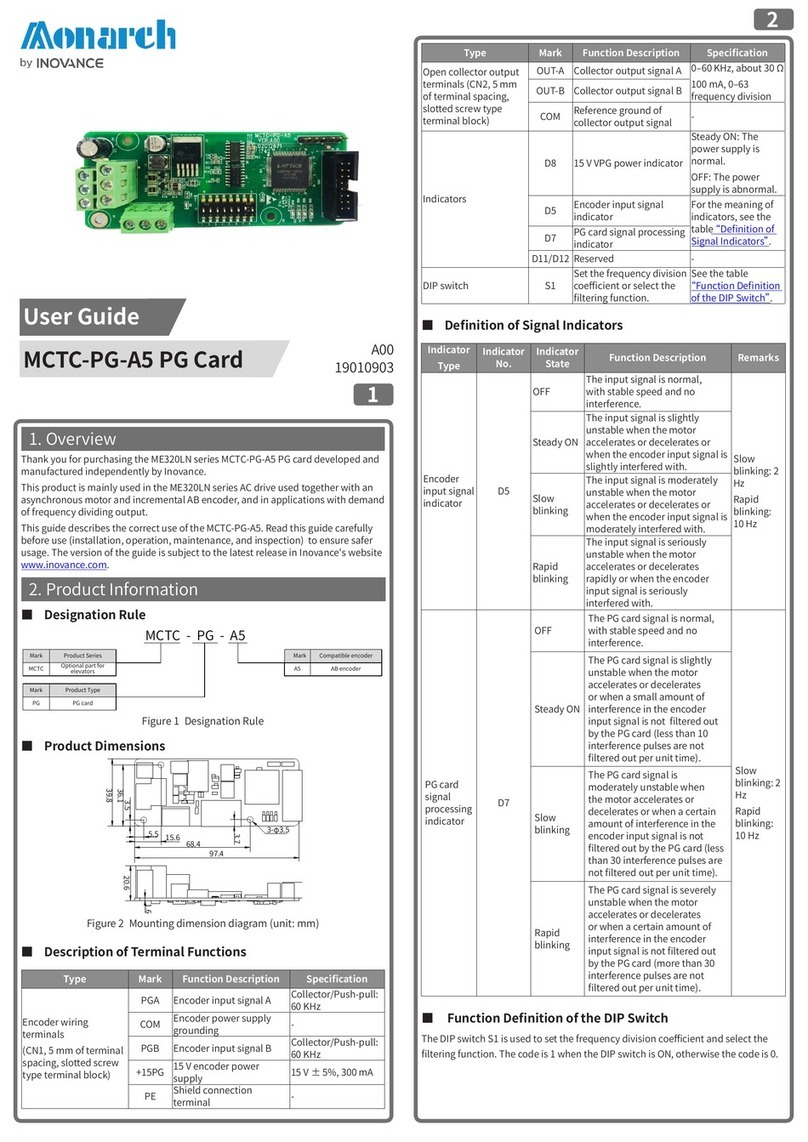
Thank you for purchasing the MCTC-PG-E6 series PG card developed and
manufactured independently by Inovance.
This product is compatible with the SIN/COS rotary encoder.
This guide describes the correct use of the MCTC-PG-E6. Read this guide carefully
before use (installation, operation, maintenance, and inspection) to ensure safer
usage. The version of the guide is subject to the latest release in Inovance's website
www.inovance.com.
2. Product Information
■Designation Rule
MCTC - PG - E6
Mark Product Series
MCTC Optional part for
elevators
Mark Product Type
PG PG card
Mark Compatible Encoder
SIN/COS rotary encoderE6
Figure 1 Designation Rule
■Technical Specications
Item Specication
Power supply Input 24 V, 500 mA
Output 5 V, 200 mA
Environment
requirements
Installation
environment
Indoors, free from direct sunlight, dust, corrosive
gas, combustible gas, oil mist, vapor and salt
Ambient
temperature -10℃ to 50℃
Humidity Less than 95% RH, without condensing
Vibration Less than 5.9 m/s2(0.6 g)
Storage
temperature -20℃ to 60℃
Cooling mode Self-cooling
Storage Stored in a clean and dry indoor place
Transport Transported in standard packing boxes by means
of car, train, plane, ship, or other tools.
■Terminals
Type Denition Function Description
CN2
A+ Encoder dierential input signal A
A-
B+ Encoder dierential input signal B
B-
Z+ Encoder dierential input signal Z
Z-
CN3
VCC Output power: 5 V, 200 mA
COM Grounding terminal
C+ Encoder dierential input signal C
C-
D+ Encoder dierential input signal D
D-
3. Installation and Wiring
■Mounting Dimensions
55.12
41.4
Ø3.5
84
74.17
17.8
1.6
17.6
16.1
8.35
Figure 2 Mounting dimension diagram (unit: mm)
■Wiring of the PG card
编码器
A+
A-
B+
B-
Z+
Z-
5V
CO
M
C+
C-
D+
D-
控
制
板
PG
卡
接
口
Encoder
PG card interface of the
control board
Box header
connector
(28 PIN)
Figure 3 Wiring of the PG card
4. EMC Guidelines
1 ) During on-site installation and commissioning, the signal cables (such as
the encoder cables) and power cables must be laid in dierent ducts. Never
bundle the encoder cables and power cables together to prevent the encoder
interference.
2 ) The motor housing must be connected to the PE terminal of the AC drive, and
the grounding cable on the side of the motor housing must be connected
properly.
3 ) It is recommended to use the shielded twisted pair cables. For the dierential
encoder, the cables must be twisted with dierential pairs and the cable shield
must be connected to the PE terminal of the AC drive.
4 ) For some large-scale equipment, the long motor cable (>10 m) caused by
the long distance between the AC drive and the motor can result in high
inductance, which aects the grounding eect. In this condition, the encoder
shield needs not to be connected to the PE terminal of the AC drive.
MCTC-PG-E6 PG Card
User Guide
19010902A01
*19010902A01*


