1
WEILER E1250
1-2
General Information
1
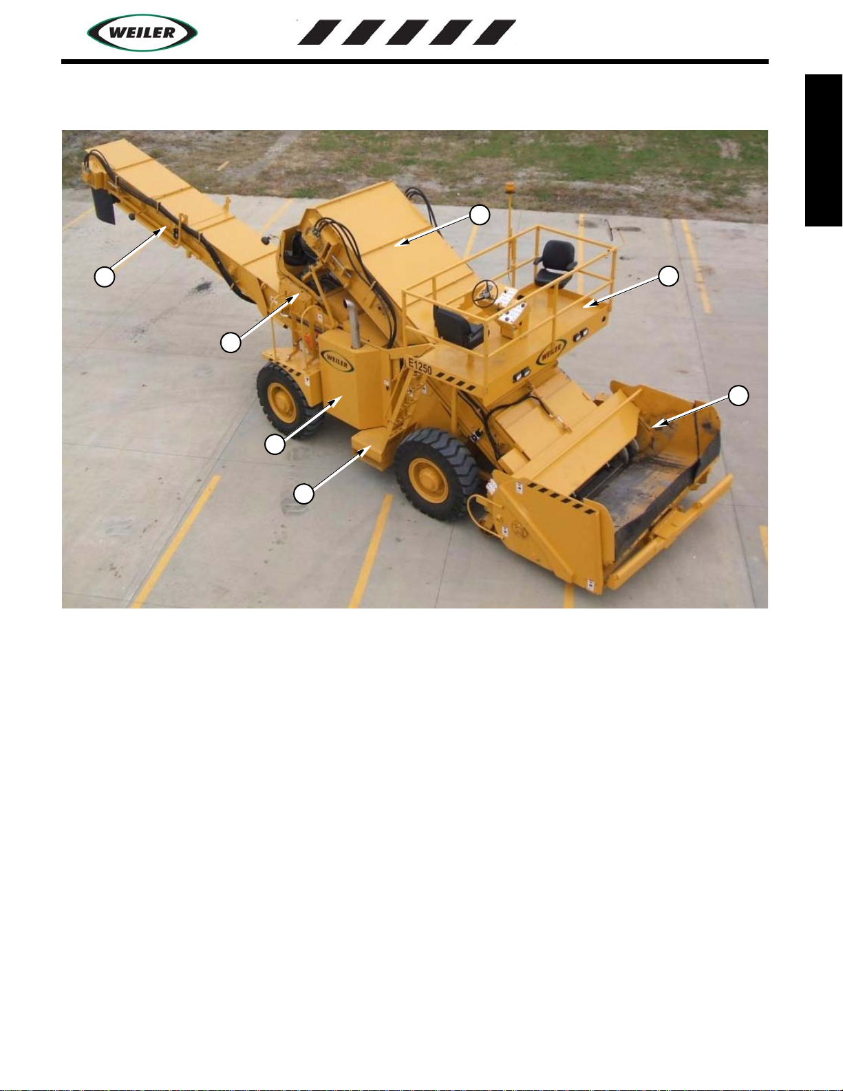
MACHINE DESCRIPTION
The Weiler E1250 is a self-propelled elevator used for
transfering hot-mix asphalt from transport vehicles to an
asphalt paver. The E1250 is used in non-contact,
continuous paving and helps to eliminate truck end
segregation, and add a surge capacity to the paving train.
Optional Weiler hopper inserts for the paver will add
more capacity as well.
The E1250 is equipped with a CAT C7, 250 HP, 6-
cylinder turbocharged diesel engine. Power is
transmitted to all four wheels on the E1250, through two
variable speed hydrostatic pumps, driving four two-
speed hydrostatic motors and planetaries. The two
speed hydraulic motors allow smooth on-the-go shifting
at any speeds.
High-flotation 20 ply 17.5” x 25” tires and differential
lock allow the Weiler E1250 to operate in numerous
paving conditions from first to final lifts. The short
wheel base with set forward axle and wide stance, along
with low center of gravity, allow the E1250 to be very
stable and have a very tight turning radius of 17’.
Material is dumped into the wide, high capacity dump
hopper, where it is picked up by 28” diameter, wear
resistant augers. The augers move the material to the
drag slats in the center of the machine where it is
conveyed up the 60” wide elevator and discharges into
either the conveyor or the optional remix hopper. In the
remix hopper, two 16” diameter interlaced augers mix
the material and move it to the center of the machine to
transfer to the conveyor. The conveyor transfers the
material into either the paver hopper or the optional
hopper insert. The conveyor swings 55 degrees from
center in each direction and raises up to 12 feet off of the
ground. This allows the machine to be very versatile
and be used for paving over string lines, barrier walls,
and other obstacles encountered in the paving operation.
The elevator and conveyor on the Weiler E1250 are
powered by variable speed hydrostatic pumps and high-
torque direct drive motors. The elevator is rated at 1000
tons per hour and the conveyor is rated at 600 tons per
hour.
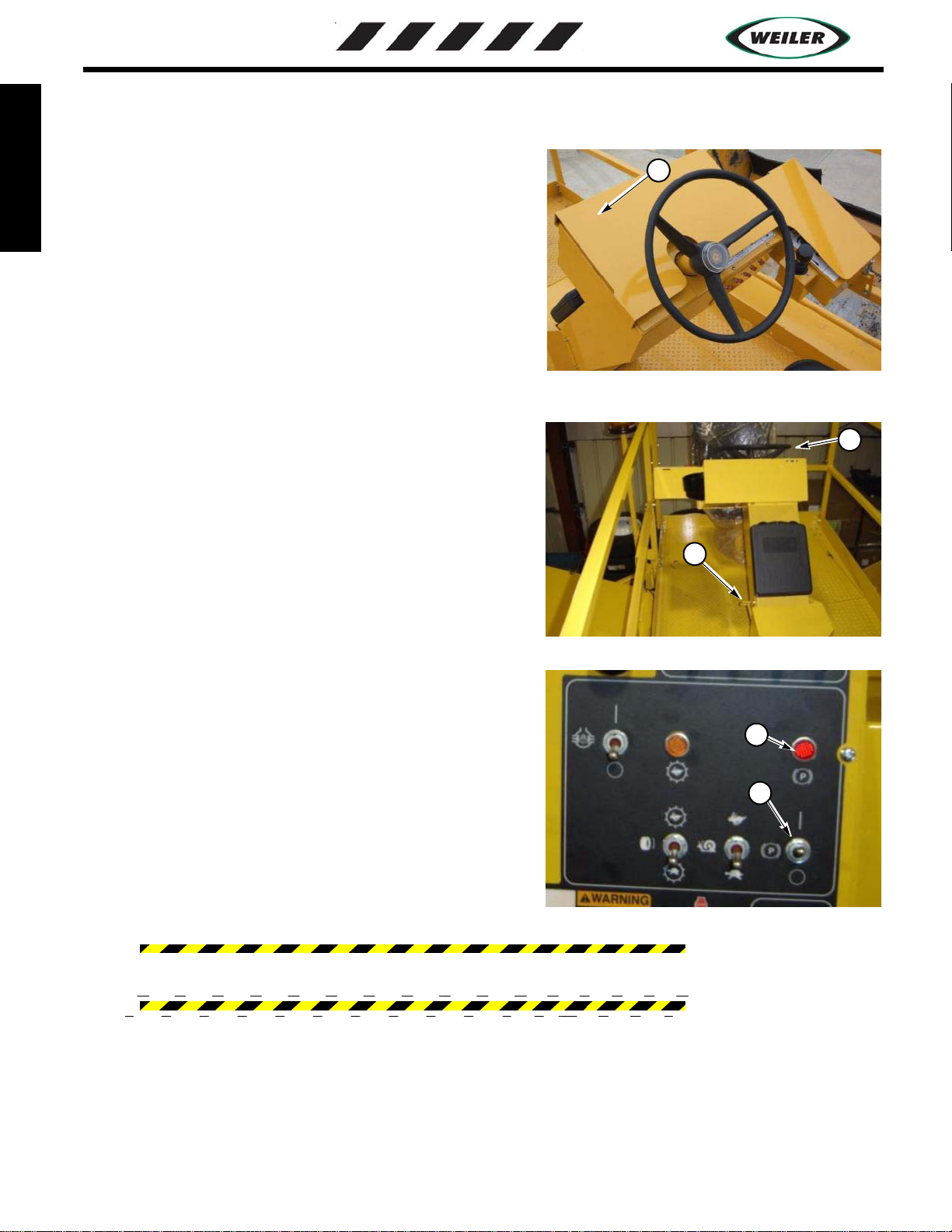
A dual position, rotating operator’s station is provided
along with two operator’s seats to allow for the operator
to move from left to ride side of the machine. All
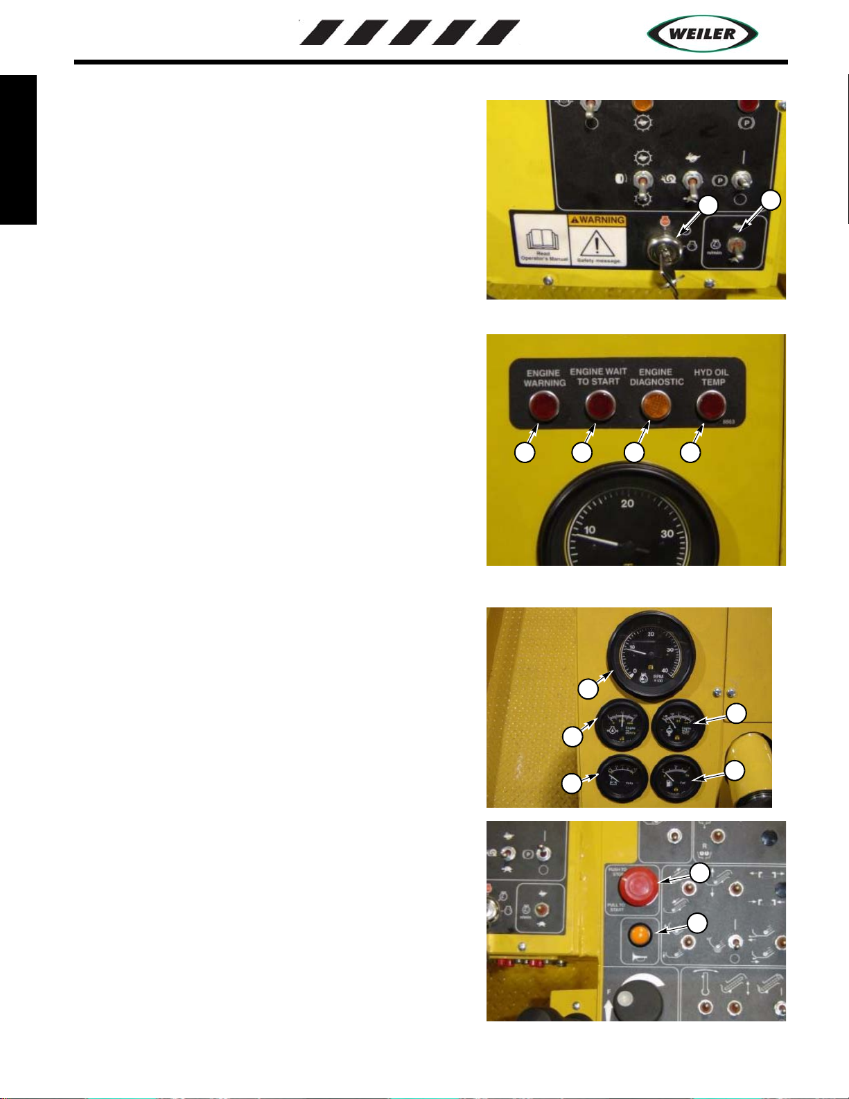
operation functions are controlled from the operators
platform. Two control panels are located on the ground
near dump hopper on either side of the machine for the
truck dump operator to control the hopper functions, as
well as clean out functions. An additional service
control panel is located near the rear of the machine to
aid in conveyor and mix hopper clean up.
A washdown system with electrical pump is provided
with each machine along with a separate tank for wash
down solvents. The wash down system includes a 50ft
hose reel and quick attach wand for reducing asphalt
build up on the contacted components and lubricating
them before use.
Options avaliable are rotating beacon light, 9KW
generator, additional working lights, hopper insert, truck
hitch, windrow pickup unit, and cold start kit.