Instar IN-4011 User manual

Chromium
Firefox
Internet Explorer
Safari
/ Automatic 4x Optical Zoom
/ Scheduled motion detection via image analysis
/ Pan & Tilt control: horizontal 355° / vertical 90°
/ Auto-swtching IR-Cut Filter delivers vibrant colour image
/ Night Vision through 66 integrated IR-LEDs
/ Automatic alarm by email and FTP snapshot upload
/ Video recording via your Internet Explorer
/ Easy camera configuration via the integrated WebUI
/ Multi-level user managment and access control
/ Remote access via web browser (free DDNS service)
/ Full smartphone integration (iOS & Android App)
/ Easy integration into your existing WiFi/LAN network
/ MJPEG video compression for plugin-free playback
User Manual
IN-4011
4011

4011

1
INSTAR
e following topics will be shortly explained in this Quick Installation Guide:
INSTAR VGA IP Camera – Quick Installation
IN-4011 WiFi/LAN IP Camera
1. SAFETY WARNINGS...............................................................................3
2. PRODUCT FEATURES.............................................................................4
3. INSTALLATION..........................................................................................5
4. START UP...................................................................................................8
5. THE WEB USER INTERFACE................................................................11
5.1 SOFTWARE..............................................................................................12
5.1.1 LANGUAGE...................................................................................................12
5.1.2 BACKUP..........................................................................................................12
5.1.3 UPGRADE......................................................................................................12
5.1.4 RESET..............................................................................................................12
5.1.5 REBOOT.........................................................................................................12
5.2 NETWORK...............................................................................................13
5.2.1 IP CONFIGURATION.................................................................................13
5.2.2 WiFi.................................................................................................................13
5.2.3 DDNS..............................................................................................................14
5.2.4 UPnP................................................................................................................15
5.2.5 ADSL...............................................................................................................15
5.3 DISPLAY...................................................................................................15
5.3.1 VIEW ONLOAD...........................................................................................15
5.3.2 MULTI DEVICE (only Internet Explorer).................................................15
5.3.3 SIMPLE VIEW...............................................................................................15
5.4 SYSTEM....................................................................................................16
5.4.1 DEVICE INFO...............................................................................................16
5.4.2 ALIAS..............................................................................................................16
5.4.3 DATE&TIME.................................................................................................16
5.4.4 USER...............................................................................................................17
5.4.5 LOG.................................................................................................................17
5.5 ALARM.....................................................................................................18
5.5.1 ALARM...........................................................................................................18
5.5.2 EMAIL.............................................................................................................19

2
Your Manufacturer for Network and
Security Technology
More information (German/English) can be found
on www.instar.de
is Quick-Installation Guide
was made exclusively for INSTAR customers.
5.5.3 FTP...................................................................................................................19
5.5.4 SERVER...........................................................................................................20
5.5.5 PATH (only Internet Explorer).....................................................................21
5.6 MENU BAR.............................................................................................21
5.6.1 SNAPSHOT....................................................................................................21
5.6.2 RECORD (only Internet Explorer)..............................................................21
5.6.3 AUDIO (only Internet Explorer)..................................................................21
5.6.4 TALK (only Internet Explorer).....................................................................21
5.6.6 HELP................................................................................................................21
5.7 VIDEO MENU BAR.................................................................................22
5.8 PTZ - PAN&TILT CONTROL..................................................................23
5.8.1 CONTROL PAD............................................................................................23
5.8.2 POSITIONS....................................................................................................23
7. RESET YOUR CAMERA..........................................................................23
6. FIRMWARE UPDATE..............................................................................24
8. LENSEADJUSTMENT.............................................................................24
9. NIGHT VISION.......................................................................................25
10. ANDROID AND iPHONE APP.............................................................27
11. WINDOWS SOFTWARE.........................................................................28
12. VIDEO STREAMING...............................................................................29
13. TECHNICAL DATA.................................................................................30
14. WARRANTY & DISPOSAL....................................................................31
15. FAQ Questions&Answers........................................................................32
16. AVAILABLE ACCESSORIES..................................................................33

3
CE-Conformity
1 SAFETY WARNINGS
l
Please read the following safety warnings carefully and keep them in a safe place.
is device suites the basic requirements of the European regulations for electromagnetic
compliance (2004/108/EC) and the low voltage regulations (2006/95/EC ).
Please read the following safety warnings carefully and keep them in a safe place.
Make sure the power cord is not near any hot surfaces.
Place the power and network cable properly so that no one can be hurt.
To avoid damage to the pan and tilt mechanics, never try to pan or tilt the lense by
hand.
is device shall not be used by people (including children) with limited
physical, sensory and mental capabilities. Only the trained person that knows
how to use the device carefully can use the device.
Children should be supervised to make sure they don’t play with the device.
If the power cord of this device gets damaged, it can only be replaced by the
manufacturer or the customer service person or a similar qualied person to
avoid any damage to you and the device.
Never do any repair by yourself. By opening the device the warranty will automatical-
ly expire. If any repair is needed, please contact your INSTAR Service Center.
When cleaning, please never place the device in water.
Make sure you only install the device in a 100V - 230V power socket.
Only use this device to secure your home, oce and similar places. If you are plan-
ning to install the device in an public area please make sure you have all certicates
to do so.
Never install the device near explosive or ammable substances.
Don’t use the camera for any other purpose that it isn’t made for.
INSTAR does not give any warranty if you use any third party rmware or WebUI.
»
»
»
»
»
»
»
»
»
»
»
»
»

4
2 PRODUCT FEATURES
l
»High Quality Weather-Proof IP-65 Metal Camera Housing
»Integrated Alarm I/O Relay for External Sensors and Signalling Devices
»Resolution: 640 x 480 (VGA), 320 x 240 (QVGA), 160 x 120 (QQVGA)
»Interchangeable Lenses with a Wide Range of Focal Length
»Automatic 4x optical Zoom Lense
»Infrared Cut-Filter automatically lters IR-lights in bright environments
»Short-range IR-LED lighting allows Night Vision
»Pan & Tilt mechanism: horizontal 355° vertical 90°
»Audio-Input and Audio-Output can be used as a two-way intercom system
»High-sensitive 1/5 inch CMOS sensor (300.000 Pixel)
»Supported Network Protocols: TCP/IP, HTTP, ARP, RARP, TCP, ICMP, DHCP, UPnP
»Integrated 10/100Mbit Network Interface
»Supports W-LAN (Wi-Fi 802.11b/g/n)
»Integrated Webserver with Web User Interface (based on HTML5/CSS3 and jQuery)
»Free DDNS Address for Remote Access preinstalled
»MJPEG Video Compression
»Snapshot Function and Video Recording (the latter only in Internet Explorer!)
»Adjustable Framerate (only in Internet Explorer)
»Remote Pan and Tilt control
»Motion Detection Alarm Notication by Email (6 Snapshots)
»FTP Snapshot Upload - Continuous and Alarm Triggered
Hardware
Connectivity
Software

5
3 INSTALLATION
l
1Lense Standard Zoom-Lense
(4x optical zoom, focal length: 3.7-14.8mm, 18-56°)
2 Photosensor Triggers the IR-Cut Filter
3 Infrared LEDs Enables short-range Nightvision (850nm)
4 Audio-Input Audio-Transmission (Internet Explorer or ASF Stream)
5 Audio-Output Headphone / active loudspeaker connector
6 Power Connector 12V/3A DC voltage / plug: 2.1mm inside, 5.5mm outside
7 Reset Button Reset to factory settings
8 I/O-Output For external alarm indicator
(potential-free alarm output: max. 60VDC/125VAC and 1A)
9 I/O-Input For external motion detector
10 Network Port RJ45 Connector for the supplied LAN Cable
11 Antenna Connector RP-SMA wi antenna connector
12 Antenna To ensure a stable WiFi-connection
11
21 4 5 6 7 8 9
12
103

6
e green LED signals a hardware link to your router and
therefore should be on continuously. e orange LED
should be ashing irregularly indicating network trac.
e green status LED on the powersupply has to be on con-
tinuously indicating a steady power supply. Please plug the
powersupply directly into a wall socket. Using it on a multi
power strip or an extension cord is not recommended.
Connect the camera to your Network
Connect the WiFi antenna to the RP-SMA connector on
the back of camera (see #11 and #12, page 5), align it ver-
tically to your router and place the camera close to your
Wi router for the rest of the installation process. Please
be aware that the camera has to be installed via LAN cable
rst before it can be used in your wireless network.
Connect the power adapter to the camera cable (see #6, page 5)
and plug it into a suitable power outlet. Both network indicator
LEDs on the network port will light up showing that the cam-
era is connected to your network and the camera will execute
a pan&tilt calibration. An IP-address will be assigned to your
camera.
Plug the ethernet cable to the RJ45 LAN port on
the camera case (see #10, page 5) and use it to con-
nect the camera to a free LAN port of your network
router. For a direct connection to your Windows PC
or Mac, please refer to our online FAQ section on
www.faq.instar.de. We recommend to connect the
camera to your network router for the initial instal-
lation.
Take out the package content from the box: the camera, a CAT5e LAN cable, a 10dBi RP-
SMA WiFi antenna, mounting bracket, microphone with Y-Cable and the soware CD.
Chromium
Firefox
InternetExplorer
Safari
4009
/ Scheduled motion detection via image analysis
/ Automatic alarm byemail and F TP snapshotupload
/ Videorecording via your Internet Explorer
/ Easy camera configuration via the integrated WebUI
/ Multi-leveluser managment and access control
/ Accessible overthe internet DDNS
/ Full smartphone integration(iOS & Android App)
/ Easy integration into your existing WiFi/LAN network
/ MJPEG video compression for plugin-free playback
User Manual
IN-4009

7
Troubleshooting
e green LED isn’t on
Your camera doesn’t have a connection to your router, because the LAN cable is dam-
aged, the connector is loose or your camera is connected to a wrong port on your router
or switch.
e green LED goes on and o every x seconds
Your camera is continously restarting - probably because of a loose contact. Please check
the power connector on the camera side. Turn the plug by 180 degrees in both direction
and check if the problem persists. Make sure the green status LED on the power supply
is on continuously.
Connect the camera using an IN-LAN® Adapter (optional)
Simply plug one IN-LAN adapter into a power socket next to your broadband router
and connect the adapter to your router via an Ethernet cable. Plug the second IN-LAN
unit into an outlet close to your INSTAR camera and connect the camera to the IN-LAN
adapter using the camera’s Ethernet cable.
IN-LAN 500/p
Powerline Adapter
IN-LAN uses the household pow-
er grid to transfer data between
computers equipped with suitable
Additional accessories, like the IN-LAN Adapter, can be found in the accessories of your camera model on www.instar.de and are sold separately.
adapters and other network components. As a result, any power outlet can be used as a
network access point. IN-LAN is an intelligent and secure technology that lets you set
up a home network easily via your household power grid - without the need of complex
and expensive dedicated cabling.
For a direct cable connection between camera and computer, please note:
e network cable provided with the camera is not a crossover cable. It is just a nor-
mal patch cable. Most modern computers network interfaces support the automatic
switching between crossover and normal patch cable - you can use the cable that came
with the camera to connect it directly. If you are using an older system to connect your
camera directly you might need a crossover network cable.
To set up the camera for the rst installation we recommend to connect the camera
directly to your router. is router on the other side has to be connected with your com-
puter. Other ways of connections are only recommended to experienced users. Please
refer to our online documentation on www.faq.instar.de.
8
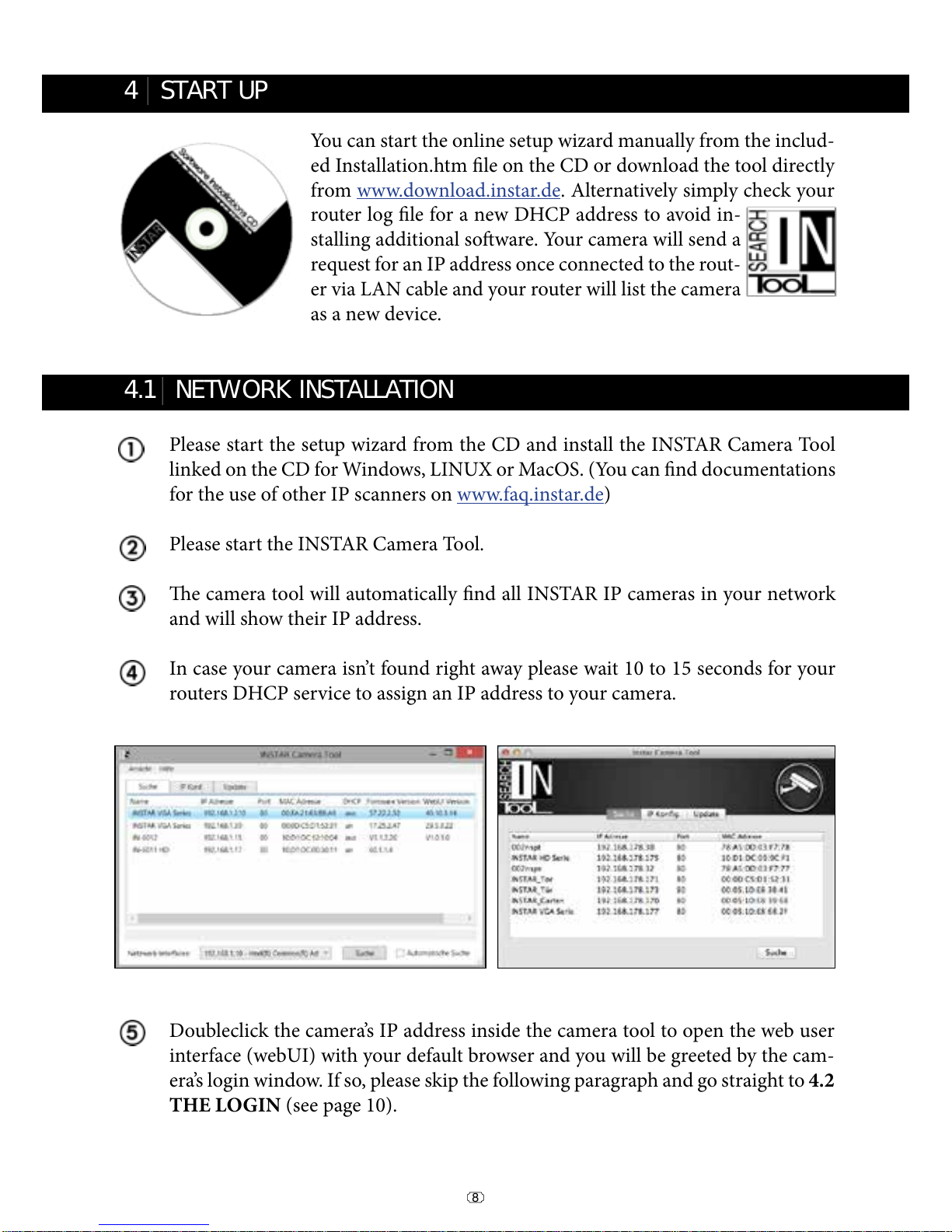
Please start the setup wizard from the CD and install the INSTAR Camera Tool
linked on the CD for Windows, LINUX or MacOS. (You can nd documentations
for the use of other IP scanners on www.faq.instar.de)
Please start the INSTAR Camera Tool.
e camera tool will automatically nd all INSTAR IP cameras in your network
and will show their IP address.
In case your camera isn’t found right away please wait 10 to 15 seconds for your
routers DHCP service to assign an IP address to your camera.
You can start the online setup wizard manually from the includ-
ed Installation.htm le on the CD or download the tool directly
from www.download.instar.de. Alternatively simply check your
router log le for a new DHCP address to avoid in-
stalling additional soware. Your camera will send a
request for an IP address once connected to the rout-
er via LAN cable and your router will list the camera
as a new device.
4 START UP
4.1 NETWORK INSTALLATION
l
l
Doubleclick the camera’s IP address inside the camera tool to open the web user
interface (webUI) with your default browser and you will be greeted by the cam-
era’s login window. If so, please skip the following paragraph and go straight to 4.2
THE LOGIN (see page 10).

9
To check the IP address of your Windows computer and your network parameters
please do the following:
1. Click on [START] -> and type in „cmd” into the search eld.
2. In the window that pops up please type „ipcong”.
3. Now the IP address and the subnet mask will be shown.
In case your camera isn’t automatically assigned an IP address, the camera will be
shown inside a wrong IP address space. A double click on the camera’s IP will then
open the IP / Network conguration window (see below) allowing to manually assign
an address.
Please set the following information according to your network:
- IP Address (for example 192.168.x.x)
- Subnet Mask (for example 255.255.255.0)
- Gateway (IP Address of your router; for example 192.168.x.1)
- DNS Server (IP Address of your router; for example 192.168.x.1)
- Http Port (TCP Port; for example 80)
In case the INSTAR Camera Tool doesn’t nd your INSTAR IP camera please make
sure that both status LEDs on the LAN connector are active - the green LED should be
continuously on indicating a hardware link and the orange LED should ash irregularly
showing network communication.(see page 7).
Troubleshooting:
10
How to setup your Camera without a router:
If you want to connect your camera directly to your computer, please set a xed IP
address for the network interface in your computer, as well as for the IP camera. You
can set the camera IP by using the INSTAR Camera Tool. As for Gateway and DNS
server please ll in the computer IP. Aer submitting the settings to the camera please
wait a moment until the camera has restarted. For a detailed instruction please refer to
our FAQ section on www.faq.instar.de.
EXAMPLE:
If your computer’s IP address is “192.168.178.10” then please give your camera an
IP like this “192.168.178.110”. For Subnet mask, Gateway and DNS Server please
use the same settings as for your computer (s. above). If your computer has the IP
“192.168.178.10” then the Gateway and DNS should be “192.168.178.1” and the sub
netmask is “255.255.255.0”.
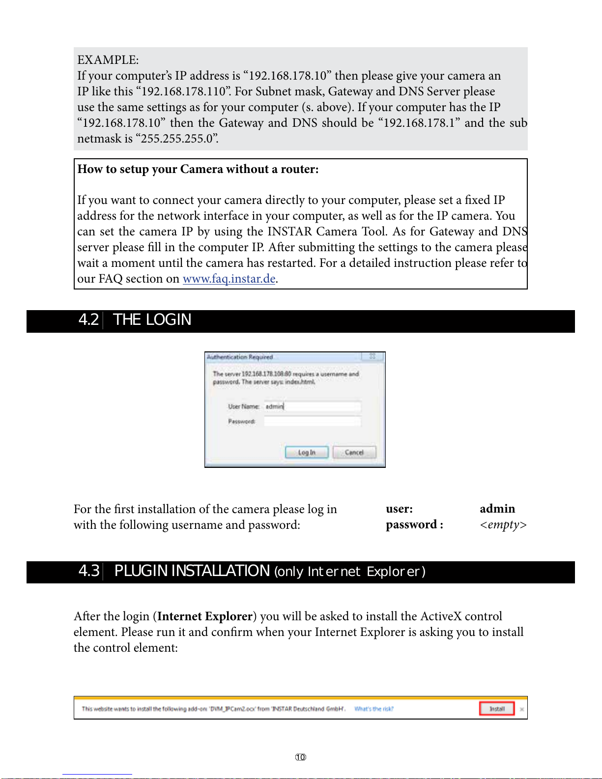
For the rst installation of the camera please log in
with the following username and password:
Aer the login (Internet Explorer) you will be asked to install the ActiveX control
element. Please run it and conrm when your Internet Explorer is asking you to install
the control element:
4.2 THE LOGIN
4.3 PLUGIN INSTALLATION (only Internet Explorer)
l
l
user: admin
password : <empty>

11
5 THE WEB USER INTERFACE
l
When accessing the webUI for the rst time aer installation, please allow the installa-
tion of the ActiveX control element (only Internet Explorer):
For alternative browsers (Firefox, Chrome, Safari, etc...) no additional Plugins are
needed. You can quickly access your camera’s video stream and adjust its settings. Use
alternative browser on computers where you lack the administration rights to install the
ActiveX plugin (for example in the oce).

12
5.1 SOFTWARE
l
5.1.3 SOFTWARE/UPGRADE
5.1.4 SOFTWARE/RESET
5.1.5 SOFTWARE/REBOOT
Here you can choose the language of the
web user interface. e web user interface
will reload aer you click submit.
You can download rmware and WebUI
updates from our homepage www.down-
load.instar.de and install them using the
Upgrade mask.
Click on Reboot to reboot your camera’s
operating system.
5.1.1 SOFTWARE/LANGUAGE
5.1.2 SOFTWARE/BACKUP
To save your camera settings please click
the upper Submit button. e default le
name for the backup is params.bin and
the le path is the download folder of your
browser. To restore the settings, e.g. aer a
factory reset, please click Browse to search for the backup le and click Submit to restore
the settings.
Click on Reset to reset your camera’s so-
ware to the factory defaults. In case you
misplaced the camera’s password please use
the optional Reset Button (s. S.5 #7) to go
back to the standard login.

13
5.2 NETWORK
l
5.2.2 NETWORK/WiFi
To integrate the camera into you local WiFi
network, please click the Search button
2 times to start the WiFi scanner. Choose
your own network and click on its name.
Now you simply have to add the WiFi pass-
word (Share Key) and click submit to save the settings. Please wait for the camera to
reboot - then disconnect the LAN cable. e camera will automatically - within max.
5 minutes - connect to your WiFi network. e camera’s WiFi module might receive a
new address from your router - if you didn’t assign a static IP address to your camera
yet (s. 5.2.1). You might have to use the INSTAR Camera Tool again to rediscover your
camera (s. 4). Your camera is now connected via WiFi!
Additional Remark:
Your camera supports a range of encryption standards - we recommend for your safety
and reliability of your connection, that you set your WiFi network to WPA2 (PSK) with
AES (or CCMP). With older routers choose WPA (PSK) / AES. Avoid using a mixed
mode like WPA&WPA2 - TKIP! If your WiFi stays unstable please choose a xed WiFi
channel for your router - we recommend the channels 1 - 6.
Attention:
Your WiFi modules MAC address is not identical with the LAN MAC address of your
camera! In case you are using a MAC ltering rule for your WiFi network please deac-
tivate the lter and add your camera to the list of trusted devices before reactivating it.
Please refer to your routers manual for further instructions.
5.2.1 NETWORK/IP CONFIGURATION
You can set whether the camera will be as-
signed an IP address by your router (DHCP)
or if you want to set a xed address manual-
ly. Please check page 9 on how to set a xed
IP address. In general, we recommend that
you deactivate the automatic service and set a manual IP to avoid further trouble with
the remote access to your camera.

14
In case you want to use an account from DynDNS.org or NoIP simply choose the third
party service and type in your personal login credentials. By doing so you will tempo-
rarily deactivate your INSTAR DDNS address.
In case you are using several cameras behind a single internet access point, please set up
the third party address in only one of the cameras. Or if possible directly inside your
router! All your cameras will be accessible through this address - just assign a unique
HTTP port to every camera (s. 5.2.1). For example if camera 1 is assigned the HTTP
port 85 and camera 2 the HTTP port 86, use myaddress.dyndns.org:85 to reach camera 1
and myaddresse.dyndns.org:86 to be forwarded to camera 2.
EXAMPLE Portforwarding - Netgear:
Please refer to our online help www.faq.instar.de for detailed instructions for all com-
men routers.
Your camera comes with a personal DDNS
address - e.g. http://xxxx77.ddns-instar.de.
Everything you need for a remote access to
your camera is a port forwarding rule (s.
next page) in your router. You can access
your camera aerwards through the internet using this http address.
Please visit our online FAQ section on www.faq.instar.de for detailed information on the
port forwarding setup as well as video instruction for many common routers. Or refer to
your router’s user manual for further guidelines on how to set up a port forwarding rule.
5.2.3 NETWORK/DDNS

15
5.3 DISPLAY
l
5.2.4 NETWORK/UPnP
If you are using Universal Plug and Play for
your network devices. Please activate the
UPnP service in your camera. In case you
are using a manual port forwarding rule in
your router to access your camera from the internet, make sure the camera’s UPnP ser-
vice is deactivated! We recommend setting up a manual port forwarding.
5.2.5 NETWORK/ADSL
You can use the ADSL function to use the
camera directly plugged into a ADSL mo-
dem instead of a network router. Simply use
the login from your internet service provid-
er.
5.3.1 DISPLAY/VIEW ONLOAD
Use the View OnLoad function to set the
default view - you can choose between the
Setup View and a Simple View.
5.3.2 DISPLAY/MULTI DEVICE (only Internet Explorer!)
Use the Multi Device mask to add cameras
to your live view. Just add the camera’s IP
or DDNS address and user login and click
Add. Repeat the step for additional camer-
as and click Submit. en choose a corre-
sponding grid type in your Live-View Tab:
5.3.3 DISPLAY/SIMPLE VIEW
e Simple View is designed for your daily use
aer you nished the initial setup of your camera.
You can click on Setup View to return to the ex-
tended menu.

5.4 SYSTEM
l
16
5.4.3 SYSTEM/DATE&TIME
server synchronisation to achieve a higher accuracy for alarm trigger events. Please ac-
tivate “Consider Daylight Saving Time” when in eect.
You can set up the internal clock of the
camera to be either synchronised with your
PC clock or with one of several NTP serv-
ers. As long as your camera has access to the
internet it is recommended to use an NTP
5.4.4 SYSTEM/USERS
5.4.1 SYSTEM/DEVICE INFO
e Device Info menu gives you an overview
of several important camera parameters -
like your soware version and connection
status.
5.4.2 SYSTEM/ALIAS
Set an Alias for your camera to identify the
camera in your network.
Additional Remark:
If the phrase “No Action” is displayed under DDNS-Status in SYSTEM/INFO, please
make sure that you’ve put in the correct Gateway and DNS-Server information. Simply
go to Network -> IP Conguration and check your settings (s. 5.2.1).

17
e Access Log shows you every login to
the camera as well as the IP address of the
incoming connection. Additionally you can
nd general notications from the camera’s
operating system such as motion alerts.
5.4.4 SYSTEM/USERS
e web user interface oers a 3-level user
management with dierent access rights for
administrators, operators and visitors. You
can set user names and passwords for all
three user levels in the Users mask. Visitors
will only have access to the videostream of
the camera, Operators in addition are able to use the pan&tilt function and only the Ad-
ministrator will have access to all the camera’s conguration menus.
e Access Log shows you every login to
the camera as well as the IP address of the
incoming connection. Additionally you can
nd general notications from the camera’s
operating system such as motion alerts.
5.4.8 SYSTEM/LOG
Additional Remark:
If you wish to embedd the Live-Stream of the camera in a website, we recommend to
create a seperate User Prole with “Guest”-rights (s. 12, page 29). Further information
and a step-by-step tutorial can be found on www.faq.instar.de .

18
5.5 ALARM
l
5.5.1 ALARM/ALARM
Here you can adjust the camera’s behaviour
in case of a motion alert trigger event. Once
the motion detection is activated, its sensi-
tivity can be adjusted from very insensitive
(value=0) to very sensitive (value=10).
Your camera detects motion by a picture
analysis that is sensitive to every change inside the video frame instead of employing
an infrared or microwave sensor. In case the camera’s position is prone to rapid light
changes, e.g. changes in sun intensity due to cloud movements, you might be confronted
with a high number of false alarms.
Motion
300
IN-Motion 300
Plug & Play - PIR Motion Detector
IN-Motion 300 - the passive infrared detector es-
pecially designed for your INSTAR camera. e
simplest way to avoid false alerts by changes in
light conditions.
All components needed for the installation are al-
ready included in the delivery !
Additional accessories, like the IN-Motion 300, can be found in the accessories of your camera on www.instar.de and are not part of the scope of
the delievery.
You can use the Scheduler to automatically activate the alarm in desired time intervals.
Every blue box set inside the scheduler represents a 15 minutes time window in which
the alarm function is active.
Be aware that the internal camera time is used for the scheduler. Please make sure that
the camera’s timezone is set correctly and the daylight saving time function is activated
if indicated (s. 5.4.3).
To solve this problem you can attach an external motion detector (IN-Motion 300; s.be-
low) to the I/O relay of the camera. Please check “Activate External Input” to start using
the external sensor and set the trigger level according to your devices demands. Please
only activate the external input if an external sensor is connected - since you might re-
ceive false alerts otherwise.
Other manuals for IN-4011
1
Table of contents
Other Instar IP Camera manuals


