INSTEON 2441V User manual

Page 1 of 2
Rev. 20080213
Quick-Start Guide
INSTEON™ Thermostat Adapter, Totaline™ / Venstar™
Model: #2441V
INSTEON Thermostat Adapter
Introduction
The INSTEON Thermostat Adapter adds remote control and monitoring to 3
compatible models of TotalineTM / VenstarTM brand thermostats. It simply
plugs into the bottom of compatible thermostats and communicates via
INSTEON RF giving you wireless remote control and monitoring from
anywhere in your home, or the world.
The 3 compatible models are:
1-Day Programmable Venstar Thermostat (30410A)
7-Day Programmable Venstar Thermostat (30411A)
7-Day Programmable, Dual-Fuel Venstar Thermostat (30412A)
Note: To use the above mentioned thermostats, make sure your install
location’s wiring has 5 wires or check with a local installer.
Installation
1) Simply plug the INSTEON Thermostat Adapter into the jack on the bottom of your thermostat
Green LED will turn on
Un-Install
1) Open the front cover of the thermostat by gently pulling the right edge of the cover towards you
2) While pressing firmly on the small round button (center, bottom of thermostat) pull down gently on the INSTEON Thermostat Adapter
INSTEON Thermostat Adapter will disconnect from the thermostat
Adding your Thermostat Adapter to a Scene on an INSTEON Compatible Controller
For example, let’s say you would like to remotely control your thermostat to 73 degrees, heat mode from the comfort and convenience of your couch,
using the Scene A button on your RemoteLinc (If you want to use another INSTEON Compatible Controller, see its user manual)
Note: Linking your Adapter to a scene allows your thermostat to go to a chosen setting.
Here, you will link your Scene A button to “recall” both the setpoints and mode of the thermostat.
1) Tap the mode button on your thermostat until the mode indicated is heat
2) Tap the up and/or down arrows on your thermostat until the temperature set point is 73 degrees
3) Press & hold the top of the Scene A button on your RemoteLinc (for about 10 seconds) until it beeps
LED will start blinking (Press & hold for 10 seconds works for just about every INSTEON-compatible Controller;
please check the controller’s owner’s manual if you need help)
4) Press & hold the button on the INSTEON Thermostat Adapter (for about 5 seconds)
LCD display on your thermostat will briefly display all its characters, then return to normal
INSTEON Adapter’s LED will blink off faintly, then return to steady on
RemoteLinc will beep and its LED will stop blinking
5) Tap the mode button on your thermostat (this will temporarily change the operating mode to allow you to test your remote control)
Your thermostat’s mode will change to cool
6) Now to test your new link, tap the Scene A (up arrow) on your RemoteLinc
Your thermostat should return to heat mode with a 73-degree set point
7) Repeat steps 1 through 6 for as many scenes and setpoints on your INSTEON-Compatible Controller as you wish.
Note: Sending an Off command will not change the mode or setpoints of the thermostat. These commands are ignored to minimize unintended results.
Note: Different set points can be linked to different buttons should you need more flexibility.
Button
LED

Page 2 of 2
Rev. 20080213
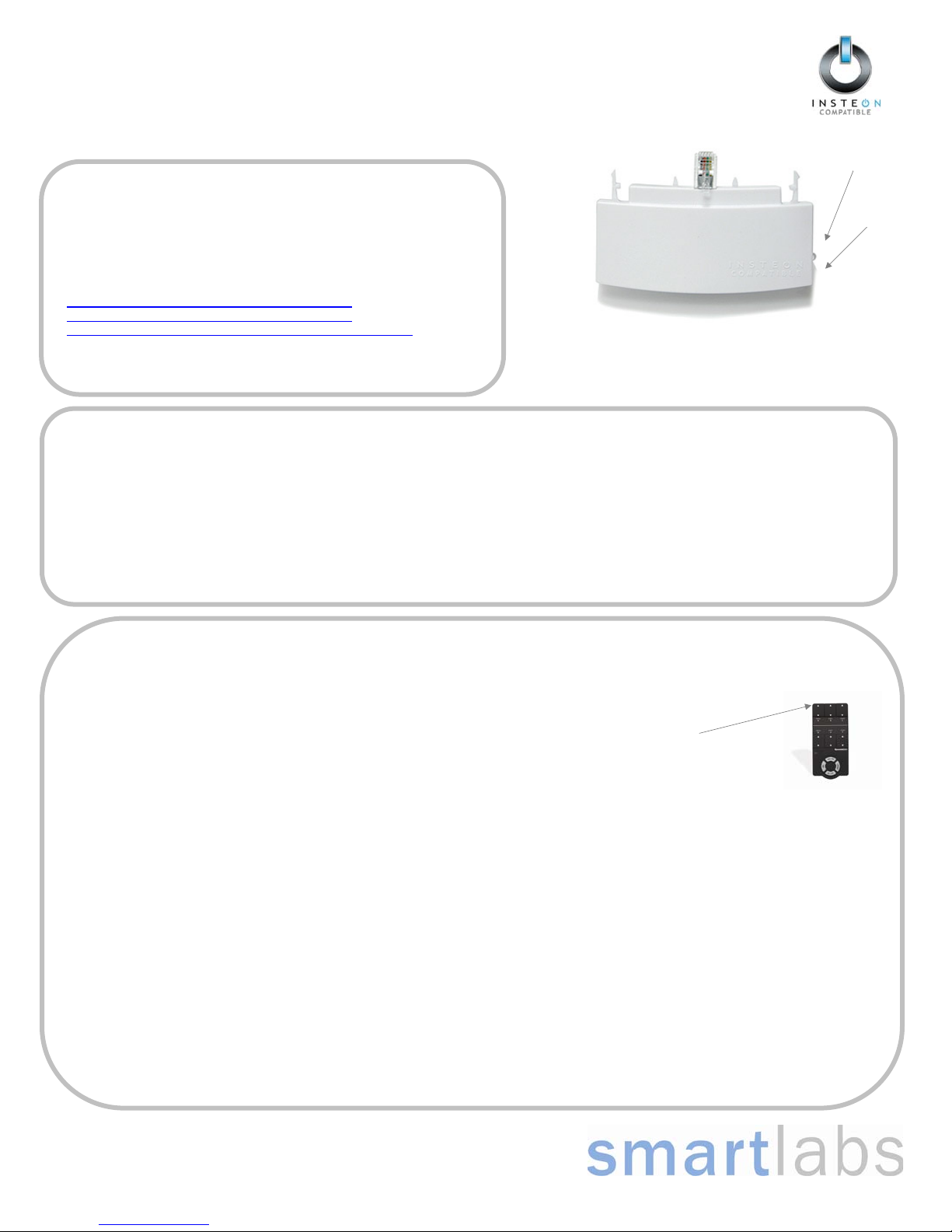
Quick-Start Guide INSTEON Thermostat Adapter
For HELP, call our friendly tech support @ 866-243-8018
SmartLabs Limited Warranty – SmartLabs warrants to the original consumer of this product that, for a period of two years from the date of purchase, this product will be free from defects in material and
workmanship and will perform in substantial conformity to the description of the product in the owner's manual and/or quick start guide. This warranty shall not apply to defects or errors caused by misuse
or neglect. © Copyright 2008 SmartLabs, 16542 Millikan Ave., Irvine, CA 92606-5027 – 866-243-8018 www.smartlabsinc.com
Removing from a Scene
1) Put your Controller into “Delete from Scene” mode (usually “Unlinking” mode (two 10-second press & holds) – please check its Owner’s Manual if
you need help)
2) Press & hold the INSTEON Thermostat Adapter’s button for about 5 seconds
The LCD display on your thermostat will briefly display all its characters, then return to normal
The INSTEON Adapter’s LED will blink off faintly, then return to steady on
Factory Reset
1) Unplug the INSTEON Thermostat Adapter from your thermostat (see Un-Install section on page 1 for details)
2) Press & hold the button on the INSTEON Thermostat Adapter
3) While continuing to hold the button, plug the INSTEON Thermostat Adapter back into your thermostat
4) Continue to hold the button for approximately 5 seconds
All user settings will be erased and the unit restored to its factory settings
Advanced Operations
Using software, you will be able to integrate the automation of your thermostat with the wide array of INSTEON compatible products saving you
time and energy. For example, applications can include having an email sent to you if the temperature goes above or below any chosen set points,
have a “goodbye” scene automatically set back your thermostat, etc. – the applications are almost endless. Check with your favorite INSTEON
Compatible Software for their latest support for this product.
Specifications FCC Compliance Statement
INSTEON communications RF
INSTEON Controller functionality Not supported
INSTEON Responder functionality Supported
INSTEON message repeating Supported, always on
Mode control Heat, Cool, Auto, OFF
Fan control On, Auto
Degree format Fahrenheit (Celsius is not available)
Maximum number of INSTEON
scenes / links
417
All Linking Supported (10 sec set button push n hold)
Unlink Supported (10 seconds press n hold, twice)
Heat set point Supports all set points of Thermostat
Cool set point Supports all set points of Thermostat
Temperature status request Supported
Humidity status request Supported
Mode status request Supported
Fan status request Supported
X10 Not supported
Dimensions 2.89” W x 1.75” H x 0.58” D
LED Green
Interconnect type Male, RJ10 4 conductor (aka RJ22)
Input power 5VDC, 30 ma max (supplied by thermostat)
Installation Indoor use only
Approvals FCC, Industry Canada
Warranty 2 years
This device complies with FCC Rules Part 15.
Operation is subject to two conditions:
(1) This device may not cause harmful interference,
and
(2) this device must accept any interference that
may be received or that may cause undesired
operation. The digital circuitry of this device has
been tested and found to comply with the limits for a
Class B digital device, pursuant to Part 15 of the
FCC Rules. These limits are designed to provide
reasonable protection against harmful interference
in residential installations. This equipment
generates, uses and can radiate radio frequency
energy and, if not installed and used in accordance
with the instructions, may cause harmful
interference to radio and television reception.
However, there is no guarantee that interference will
not occur in a particular installation. If this device
does cause such interference, which can be verified
by turning the device off and on, the user is
encouraged to eliminate the interference by one or
more of the following measures:
xRe-orient or re-locate the receiving antenna of
the device experiencing the interference.
xIncrease the distance between this device
and the receiver.
xConnect the device to an AC outlet on a
circuit different from the one that supplies
power to the receiver.
xConsult the dealer or an experienced radio/TV
technician.
WARNING! Changes or modifications to this unit
not expressly approved by the party responsible for
compliance could void the user's authority to
operate the equipment.

Venstar Inc. 08/07
Use with most Air Conditioning & Heating Systems including: 1 or 2 Stage
Electric Cooling & 3 Stage Gas Heating, Heat Pump, Electric or Hydronic Heat.
Digital
Thermostat
Digital
Thermostat
residential
T1
800
HEAT
COOL HEAT
PUMP
PROGRAMMABLE
7-DAY
PROGRAMMABLE
7-DAY
up to
& 2-cool
up to
& 2-cool
3-heat
3-heat
THERMOSTAT
INSTALLATION
INSTRUCTIONS
INSTALLATION
INSTRUCTIONS
Outdoor Sensor Ready
with High/Low Readouts
for the Day
Accepts Optional Humidity Module:
Controls Humidification and
Dehumidification
Accepts EZ Programmer
Accepts Optional IR Remote Control
Accepts Comfort Call
Phone Control Accessory
Control up to 3 Heat &
2 Cool Stages
3 Configurable Outputs
Timers & Deadbands
Backlit Display & Button
Legends
Aux Heat Indicator
Adjustable 2nd & 3rd Stage

Page
i
NOTE: Due to variations in environmental conditions, it is not
always possible to achieve the desired humidification or
dehumidification setpoint.
This device complies with Part 15 of the FCC Rules. Operation is
subject to the following two conditions: (1) this device may not cause
harmful interference, and (2) this device must accept any interference
received, including interference that may cause undesired operation.
Follow the Installation Instructions before proceeding.
Set the thermostat mode to “OFF” prior to changing
settings in setup or restoring Factory Defaults.
NEVER PUT MORE THAN ONE
JUMPER ON THE SAME MISC
JUMPER BLOCK!
THIS MAY DAMAGE YOUR
THERMOSTAT AND VOID
YOUR WARRANTY.
CAUTION
C
c
F
FOR HOME OR OFFICE USE
Tested to Comply
with FCC Standards
Thermostat T1800
4Z95
CAUTION
MISC3 MISC3
OK

8
2
1
3
6
7
4
5
Preparation
Remove & Replace the
Old Thermostat
Configuring the MISC
Outputs
Wiring Diagrams
Calibrating the
Thermostat Sensors
Test Operation
TroubleShooting
Page iii
Table of Contents
Wire Connections

Page 1.1
SECTION 1
Preparation
1
Assemble tools
Flat Blade
Screwdriver
Wire cutter
& Stripper
Make sure your Heater/Air Conditioner is working
properly before beginning installation of the
thermostat.
Carefully unpack the thermostat. Save the screws,
bracket, and instructions.
Turn off the power to the Heating/Air Conditioning
system at the main fuse panel. Most residential
systems have a separate breaker for disconnecting
power to the furnace.
Proper installation of the thermostat will be
accomplished by following these step by step
instructions. If you are unsure about any of these
steps, call a qualified technician for assistance.
AUTO
I2:00
Pm
H
EAT
C
OOL
72
74
AUTO
I2:00
Pm
H
EAT
C
OOL
72
74
AUTO
I2:00
Pm
H
EAT
C
OOL
72
74
AUTO
I2:00
Pm
H
EAT
C
OOL
72
74
AUTO
I2:00
Pm
H
EAT
C
OOL
72
74

Page 2.1
SECTION 2
Remove & Replace the Old Thermostat
2
Remove the cover of the old thermostat.
If it does not come off easily check for screws.
Loosen the screws holding the thermostat
base or subbase to the wall, and lift away.
Disconnect the wires from the old thermostat.
Tape the ends of the wires as you disconnect
them, and mark them with the letter of the
terminal for easy reconnection to the new
thermostat.
Keep the old thermostat for reference purposes,
until your new thermostat is functioning properly.
AUTO
I2:00
Pm
H
EAT
C
OOL
72
74
AUTO
I2:00
Pm
H
EAT
C
OOL
72
74
AUTO
I2:00
Pm
H
EAT
C
OOL
72
74
AUTO
I2:00
Pm
H
EAT
C
OOL
72
74

3
Page 3.1
Section 3 Contents:
Configuring the Jumpers........3.2
Explanation of Jumper
Settings..................................3.3
SECTION 3
Configuring the MISC Outputs

3
Page 3.2
C
Configuring the Jumpers
NEVER PUT MORE THAN
ONE JUMPER ON THE SAME
MISC JUMPER BLOCK!
DOING SO MAY DAMAGE
YOUR THERMOSTAT AND
VOID THE WARRANTY.
W3
HUM
DEHUM
MISC3 MISC2 MISC1
Y2
(MISC1
ONLY)
CAUTION
MISC3 MISC3
OK
For additional flexibility, your thermostat has three configurable
outputs. These outputs are designed to have different functions
depending on how the jumpers are set (below).
Each output, labeled MISC1, MISC2, and MISC3 may be set for one
of the five choices available.
In the diagram below, the MISC3 jumper has been set for HUM*
(humidification) operation, the MISC2 jumper has been set for
DEHUM* (dehumidification) operation, and the MISC1 jumper has
been set for W3 (3rd stage of heat) operation.
HP
GAS
B
O
ELEC
GAS
(FAN)
W1
Y1
G
R
C
MISC2
W2
MISC1
RS2
RSGND
MISC3
RS+5
Rs1
W3
HUM
DEHUM
MISC3 MISC2 MISC1
Y2
(MISC1
ONLY)
INSTALL HUMIDITY
MODULE WITH SENSING
ELEMENT OUTWARD
HUM
NO HUM
*The Humidity Module (sold separately) must
be installed to operate a humidification
and/or dehumidification system.
1
2
4
6
8
X
Z
1
5
7
9
Y
3

Page 3.3
3
The 3rd Stage of Heat is turned on when:
(A) The 1st and 2nd stages have been on for the time required (steps #22
and #23, page 13.6). It is adjustable from 0-60 minutes and the default
is two minutes.
(B) The temperature from the setpoint is equal to or greater than: the set-
point plus the 1st stage deadband (step #19, 13.5), plus the 2nd stage
deadband (step #20, 13.5) plus the 3rd stage deadband (step #21,
13.5). This 3rd stage deadband is adjustable from 0-10 degrees and
the default is two degrees.
W3 JUMPER SETTING
If the jumper for MISC1, MISC2, or MISC3 is set to W3, the corresponding MISC screw
terminal on the backplate will control a third stage of heat.
Explanation of Jumper Settings
And
Heat
Setpoint
Cool
Setpoint
Deadband Deadband DeadbandDeadbandDeadband
db 1 db 1db 2 db 2db 3 (adj. 1-6 )(adj. 0-10 )(adj. 0-10 ) (adj. 0-10 )(adj. 1-6 )
1st Stage
turn on
2nd Stage
turn on
3rd Stage
turn on
1st Stage
turn on
2nd Stage
turn on
Heating
Cooling
TEMPERATURE
DECREASE INCREASE
W3 MULTI-STAGE OPERATION EXPLAINED - SECTION 13 of the Owner’s
Manual
HUM JUMPER SETTING
If the jumper for MISC1, MISC2, or MISC3 is set to HUM,
terminal on the backplate will control a humidification system.
the corresponding MISC screw
If your HVAC unit is equipped with a humidification system and the
Humidity Module (sold separately) has been installed, the thermostat will
provide power to the MISC1, MISC2, or MISC3 terminal of the thermostat
when the humidity in the home falls below the humidity setpoint you have
chosen. The value for this setpoint ranges from 0% to 60%. If no
humidity is desired or if a humidification system has not been installed, set
the value to OFF.
HUMIDIFICATION OPERATION - SECTION 9 of the Owner’s Manual

Page 3.4
DEHUM JUMPER SETTING
Explanation of Jumper Settings (continued)
If the jumper for MISC1, MISC2, or MISC3 is set to DEHUM,
terminal on the backplate will be connected to the dehumidification terminal of a furnace board.
NOTE: Not all furnaces have a dehumidification terminal.
the corresponding MISC screw
DEHUMIDIFICATION OPERATION - SECTION 10 of the Owner’s Manual
If your HVAC unit is equipped with a dehumidification system the thermostat will
operate in one of two ways.
1) Normally Closed (NC): The thermostat will de-energize the MISC1, MISC2,
or MISC3 terminal of the thermostat (this MISC terminal is connected to the
DEHUM terminal on your furnace) to allow the fan to run in low speed when
the humidity in the home is above the dehumidify setpoint you have chosen
and there is a call for 1st stage cooling.
2) Normally Open (NO): The thermostat will energize the MISC1, MISC2, or
MISC3 terminal of the thermostat (this MISC terminal is connected to the
DEHUM terminal on your furnace) to allow the fan to run in low speed when
the humidity in the home is above the dehumidify setpoint you have chosen
and there is a call for 1st stage cooling.
3

Page 3.5
3Y2 JUMPER SETTING
If the jumper for MISC1 is set to Y2 the
second stage of cooling.
MISC1 screw terminal on the backplate will control a
Y2 OPERATION - SECTION 13 of the Owner’s Manual
Control up to two Cool stages.
The 2nd Stage of heat or cool is turned on when:
(A) The 1st Stage has been on for the time required (step #22,
page 13.6). It is adjustable from 0-60 minutes and the default
is two minutes.
(B) The temperature spread from the setpoint is equal to or greater
than: the setpoint plus the deadband (step #20, page 13.5), plus
the 2nd deadband (step #20, page 13.5). This 2nd deadband is
adjustable from 0-10 degrees and the default is two degrees.
Explanation of Jumper Settings (continued)
And
Cool
Setpoint
DeadbandDeadband
db 1 db 2
(adj. 0-10 )(adj. 1-6 )
1st Stage
turn on
2nd Stage
turn on
Cooling
TEMPERATURE
INCREASE

Page 4.1
SECTION 4
Wire Connections
4
If the terminal designations on your old thermostat
do not match those on the new thermostat, refer
to the chart below, or the wiring diagrams
that follow.
Wire from the
old thermostat
terminal marked Function
Install on the
new thermostat
connector marked
G or F Fan G
Y1, Y or C Cooling Y1
W1, W or H Heating W1/O/B
PowerRh, R, M, Vr, A R
C
O/B
C
Common
Rev. Valve
W2 2nd Stage Heat
RS+5 Remote Sensor +5vdc
Remote Sensor Signal
RS1
RSGND Remote Sensor Ground
W1/O/B*
W2
MISC1
MISC2
MISC3
MISC1
MISC2
MISC3
RS2 Remote Sensor Signal #2
Configurable Output #1
Configurable Output #2
Configurable Output #3
* O/B is used if your system is a Heat Pump.
** For instructions on connecting these terminals see page 14.2
of the Owner’s Manual.
RS+5**
RS1**
RSGND**
RS2**
AUTO
I2:00
Pm
H
EAT
C
OOL
72
74

Page 5.1
Section 5 Contents:
HVAC Equipment Wiring............5.2
MISC1, MISC2, and MISC3
Wiring........................................5.6
SECTION 5
Sample Wiring Diagrams
5

HP
GAS
B
O
ELEC
GAS
(FAN)
W1
Y1
G
R
C
MISC2
W2
MISC1
RS2
RSGND
MISC3
RS+5
RS1
W3
HUM
DEHUM
MISC3 MISC2 MISC1
Y2
(MISC1
ONLY)
INSTALL HUMIDITY
MODULE WITH SENSING
ELEMENT OUTWARD
HUM
NO HUM
Y1
G
R
C
MISC2
W1/O/B
MISC1
RS+5
RS1
RSGND
W2
6 Conductor 18 gauge
unshielded cable from the
thermostat to the equipment.
24 vac return
fan relay
compressor relay
1st stage heat circuit
W1
W2 GRC
Y1
RS2
6 Wire, 1 Stage Cooling, 1 Stage Heat
24 vac common
2nd stage heat circuit
MISC3
HP
GAS
B
O
ELEC
GAS
(FAN)
Residential & Commercial 1 Stage Cooling,
with 1st stage Gas Heat
Commercial Heat Pump 1 Stage Cooling
with 2 Stage Heat
OR
Page 5.2
5

HP
GAS
B
O
ELEC
GAS
(FAN)
W1
Y1
G
R
C
MISC2
W2
MISC1
RS2
RSGND
MISC3
RS+5
RS1
W3
HUM
DEHUM
MISC3 MISC2 MISC1
Y2
(MISC1
ONLY)
INSTALL HUMIDITY
MODULE WITH SENSING
ELEMENT OUTWARD
HUM
NO HUM
Y1
G
R
C
MISC2
W1/O/B
MISC1
RS+5
RS1
RSGND
W2
6 Conductor 18 gauge
unshielded cable from the
thermostat to the equipment.
24 vac return
fan relay
compressor relay
1st stage heat circuit
W1
W2 GRC
Y1
RS2
Residential & Commercial 1 Stage Cooling,
with 1st stage Electric Heat
6 Wire, 1 Stage Cooling, 1 Stage Heat
24 vac common
2nd stage heat circuit
MISC3
HP
GAS
B
O
ELEC
GAS
(FAN)
Page 5.3
5

HP
GAS
B
O
ELEC
GAS
(FAN)
W1
Y1
G
R
C
MISC2
W2
MISC1
RS2
RSGND
MISC3
RS+5
RS1
W3
HUM
DEHUM
MISC3 MISC2 MISC1
Y2
(MISC1
ONLY)
INSTALL HUMIDITY
MODULE WITH SENSING
ELEMENT OUTWARD
HUM
NO HUM
Y1
G
R
C
MISC2
W1/O/B
MISC1
RS+5
RS1
RSGND
W2
6 Conductor 18 gauge
unshielded cable from the
thermostat to the equipment.
24 vac return
Fan Relay
Compressor Relay
Reversing Valve
O
W2 GRC
Y1
RS2
Residential Heat Pump with O Reversing
Valve 1 Stage Cooling, with 2 stage Heat
6 Wire, 1 Stage Cooling, 2 Stage Heat
24 vac common
2nd stage heat circuit
MISC3
HP
GAS
B
O
ELEC
GAS
(FAN)
Page 5.4
5

HP
GAS
B
O
ELEC
GAS
(FAN)
W1
Y1
G
R
C
MISC2
W2
MISC1
RS2
RSGND
MISC3
RS+5
RS1
W3
HUM
DEHUM
MISC3 MISC2 MISC1
Y2
(MISC1
ONLY)
INSTALL HUMIDITY
MODULE WITH SENSING
ELEMENT OUTWARD
HUM
NO HUM
Y1
G
R
C
MISC2
W1/O/B
MISC1
RS+5
RS1
RSGND
W2
6 Conductor 18 gauge
unshielded cable from the
thermostat to the equipment.
24 vac return
W2 GRC
Y1
RS2
Residential Heat Pump with b Reversing
Valve 1 Stage Cooling, with 2 stage Heat
6 Wire, 1 Stage Cooling, 2 Stage Heat
24 vac common
2nd stage heat circuit
MISC3
HP
GAS
B
O
ELEC
GAS
(FAN)
Fan Relay
Compressor Relay
Reversing Valve
Page 5.5
5
b

HP
GAS
B
O
ELEC
GAS
(FAN)
W1
Y1
G
R
C
MISC2
W2
MISC1
RS2
RSGND
MISC3
RS+5
RS1
W3
HUM
DEHUM
MISC3 MISC2 MISC1
Y2
(MISC1
ONLY)
INSTALL HUMIDITY
MODULE WITH SENSING
ELEMENT OUTWARD
HUM
NO HUM
Y1
G
R
C
MISC2
W1/O/B
MISC1
RS+5
RS1
RSGND
W2
2nd Stage Cooling
Y2 W3
RS2
Adding a (MISC1) and (MISC3)2nd Stage of Cooling 3rd Stage of Heating
3rd Stage Heat
MISC3
W3
HUM
DEHUM
MISC3 MISC2 MISC1
Y2
(MISC1
ONLY)
Page 5.6
5

Page 5.7
5
*Requires Humidity Module.
HP
GAS
B
O
ELEC
GAS
(FAN)
W1
Y1
G
R
C
MISC2
W2
MISC1
RS2
RSGND
MISC3
RS+5
W3
PROG
HUM
DEHUM
MISC3 MISC2 MISC1
Y2
(MISC1
ONLY)
INSTALL HUMIDITY
MODULE WITH SENSING
ELEMENT OUTWARD
1
2
4
6
8
X
Z
1
5
7
9
Y
3
HUM
NO HUM
Y1
G
R
C
MISC2
W1/O/B
MISC1
RS+5
RSGND
W2
RS2
Adding a Humidification System (MISC1) and Dehumidification System (MISC2)*.
MISC3
Dehumidification
System
W3
HUM
DEHUM
MISC3 MISC2
Y2
(MISC1
ONLY)
Humidification
System
MISC1
HUM
NO HUM
1
2
4
6
8
X
Z
1
5
7
9
Y
3
Humidity Module
(Sold Separately)
RS1
RS1
Other manuals for 2441V
1
This manual suits for next models
1
Table of contents
Other INSTEON Adapter manuals