Intec CVS100 Operating instructions

CVS100
Version 1.2
(Display Software 2.5.2 6031)
Installation and
Operation Guide
Please read this guide carefully before
use and keep it for future reference.
Remember to complete and mail the
owner registration form. (Installer -
Please give this manual to the user of
this produc t after your use.)

© INTEC Video Systems, Inc.
Revision F May, 2013 2
Table of Contents
TABLE OF CONTENTS ...............................................................................................................................................................2
GENERAL INFORMATION ...................................................................................................................................................3
INTRODUCTION ........................................................................................................................................................................3
IMPORTANT INFORMATION ......................................................................................................................................................3
CERTIFICATES OF COMPLIANCE ...............................................................................................................................................3
WARNINGS AND CAUTIONS .....................................................................................................................................................4
PACKAGE CONTENTS /PARTS LIST ..........................................................................................................................................5
DESCRIPTION..........................................................................................................................................................................6
PRODUCT OVERVIEW...............................................................................................................................................................6
FEATURES ................................................................................................................................................................................6
SPECIFICATIONS.......................................................................................................................................................................6
INSTALLATION INSTRUCTIONS .......................................................................................................................................7
WIRING DIAGRAM ...................................................................................................................................................................7
DISPLAY CONNECTIONS...........................................................................................................................................................7
CONTROLLER CONNECTIONS ...................................................................................................................................................7
DISPLAY,CONTROLLER AND REMOTE INSTALLATION .............................................................................................................8
CAMERA INSTALLATION ..........................................................................................................................................................9
CABLE INSTALLATION ...........................................................................................................................................................10
CONNECTOR ALIGNMENT ...............................................................................................................................................11
HIROSE ALIGNMENT ..............................................................................................................................................................11
XL (MIL SPEC)ALIGNMENT ..................................................................................................................................................11
IMAGE ORIENTATION........................................................................................................................................................12
ORIENTATION REQUIREMENTS ..............................................................................................................................................12
HOW TO CHANGE YOUR IMAGE.............................................................................................................................................12
OPERATING INSTRUCTIONS ............................................................................................................................................12
CONTROLLER OPERATION .....................................................................................................................................................12
CVR100 (SINGLE CHANNEL REMOTE) ..................................................................................................................................12
RADAR OPERATION ...............................................................................................................................................................13
SETTING THE IMAGE ORIENTATION IN THE DISPLAY .............................................................................................................13
ON-SCREEN USER’S MENU....................................................................................................................................................14
ON-SCREEN INSTALLER’S MENU ...........................................................................................................................................15
TROUBLESHOOTING AND MAINTENANCE .................................................................................................................16
TROUBLESHOOTING ...............................................................................................................................................................16
PREVENTATIVE MAINTENANCE .............................................................................................................................................16
HOW TO GET SERVICE............................................................................................................................................................17
ADDITIONAL INFORMATION...........................................................................................................................................18
WARRANTY ...........................................................................................................................................................................18
INTEC OFFICES.....................................................................................................................................................................18
OWNER REGISTRATION..........................................................................................................................................................19
© INTEC Video Systems, Inc.
Revision F May, 2013 3
General Information
Introduction
Thank you for selecting an INTEC Car Vision®
System. Before using your system, please be sure to
read and understand these instructions carefully. If
you have any questions or concerns, please do not
hesitate to contact us toll free at 800-468-3254
(west) or 800-522-5989 (east).
This Guide is intended to provide you with
information needed to successfully install and
operate the CVS100 controller when used with an
INTEC CVD Series display that has software version
2.5.0 installed.
Important Information
Please read, follow and keep these instructions for
future reference. A copy of these instructions should
be left in the vehicle in which the system is installed.
There are no user serviceable parts inside the
system components. All service must be completed
by authorized service personnel only. Please refer to
the Warranty section described later in this manual.
Always use the proper tools, wear protective clothing
and take necessary precautions when working
around electricity to prevent electrical shock.
Use only INTEC specified and provided cables to
connect the components of the system. Use of other
than INTEC specified and supplied components and
cabling could be dangerous and result in damage to
the system components and void the warranty.
Use only INTEC specified and supplied accessories
and options when upgrading your system.
Operating the camera system on too low or too high
a voltage may damage the system.
Always confirm the view provided by the camera is
adequate for your needs prior to vehicle use.
Adjustments to the camera viewing angle should be
made before use, if necessary.
Most states have laws pertaining to motor vehicles
equipped with a video display within the driver’s field
of vision, either directly or indirectly, unless the video
display is used in conjunction with a back up safety
camera to monitor the blind spots around the
vehicle. INTEC’s products are specifically designed
to enhance vehicle safety. Use of an INTEC display
to view video in any manner other than intended
requires installation in accordance with your state
laws.
We recommend the use of the optional Radar
Sensors to enhance overall safety.
Do NOT let the Car Vision® System distract you
from driving safely.
Certificates of Compliance
RoHS
COMPLIANT
2002 / 95 / EC
This device complies with
Part 15 of the FCC rules.

© INTEC Video Systems, Inc.
Revision F May, 2013 4
Warnings and Cautions
Warnings
Do NOT attempt to connect other
electrical devices to the power wire
harness of the Car Vision® System as
this can cause an over current
situation which can lead to electrical
shock or fire.
If at any time you see or smell smoke
coming from the Car Vision®System,
stop driving, exit the vehicle and
disconnect main power. Check the
system and remove any damaged
components before you resume
normal vehicle operation.
Do NOT attach the wiring to any
moving parts, across sharp edges or
close to heat sources as this may
cause shorting of the wires and may
lead to a fire or electrical shock.
When installing the camera system
be certain that all items are secure.
Items that are not secure or mounted
in an unstable manor can come
loose and cause damage or personal
injury.
When installing the system be sure
to use only INTEC supplied brackets.
The Car Vision® camera must be
insulated from the vehicle body. The
supplied camera bracket provides
the required insulation. Failure to do
so could result in a fire and lead to
property damage or personal injury.
Do NOT install the camera in any
area that allows it to extend out past
the vehicle as this can cause injury if
it were to come in contact with
people walking around the vehicle.
Never use fuses of a larger rating
than those supplied with your Car
Vision® System. Use of larger rated
fuses can cause excessive current
through the system if a short occurs
and could lead to a fire.
Cautions
Confirm that the orientation of the
image on the display is proper. Rear
facing cameras should yield a mirror
image, where items on the left of the
vehicle appear on the left side of the
monitor.
Before you begin driving, be sure the
display controls are adjusted
properly. This will avoid unnecessary
distractions while driving.
Do NOT attempt to open or service
your equipment. Removal of the
product enclosure can lead to
electrical shock.
You should not attempt to make any
adjustments to the Car Vision®
System while driving as this can lead
to an accident. Only make
adjustments when the vehicle is
stopped.
Keep the Car Vision® System clean
and free from dirt, snow and ice. If
the camera glass or display panel
becomes dirty, clean them before
use. If they are covered with snow
and/or ice, it should be cleared off
before use. Failure to do so could
lead to an accident.
When running a cable from the
exterior to the interior of a vehicle,
care needs to be taken to seal the
entry point. Failure to do so could
allow in exhaust fumes, other toxic
gases or water.
© INTEC Video Systems, Inc.
Revision F May, 2013 5
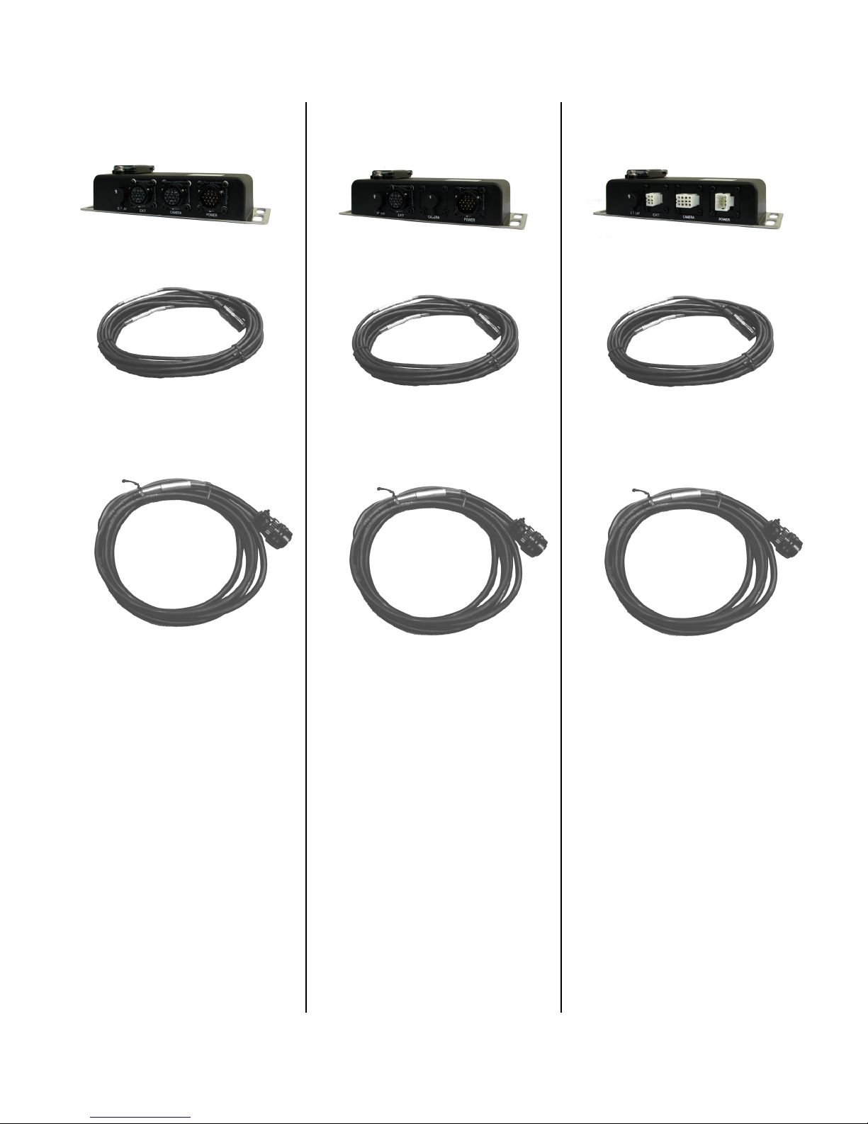
Package Contents / Parts List
CVS100XL Series
Controller
Display to Controller
cable, Part # CVDC6MA
Power cable, Part #
CVS100P3M
Mounting Hardware, Part #
107-98-02-000
CVS100H Series
Controller
Display to Controller
cable, Part # CVDC6MA
Power cable, Part #
CVS100P3M
Mounting Hardware, Part #
107-98-02-000
CVS100M Series
Controller
Display to Controller
cable, Part # CVDC6MA
Power cable, Part #
CVS100MP3M
Mounting Hardware, Part #
107-98-02-000

© INTEC Video Systems, Inc.
Revision F May, 2013 6
Description
Product Overview
The CVS100 Series of single camera controllers
have been designed to offer the user a wide range
of features and benefits along with a number of
installation possibilities. Three models are available
with connector sets to match the demands of the
application and offer installation flexibility.
The M version is designed to allow for backwards
compatibility with most of INTEC’s CVC series
camera systems.
The XL and H versions are waterproof and rated to
IP68 against water intrusion.
The XL and M versions are designed with radar
integration to give you the most advanced active
blind spot coverage of any safety camera system
today.
Features
- IP 68 waterproof controller (available in XL
and H versions)
- Automatic triggering
- Radar integration (available in XL and M
versions)
- NTSC and PAL compatibility
- External video in / out
- Backlit remote control buttons
- Double FUSE and load dump protection
Using the External Video In/Out requires an
additional video in/out cable sold separately.
Specifications
Operating Voltage: 12 / 24 VDC (Negative
Ground)
Fuse Rating: 2 Amps (Mini Blade)
Waterproof Rating: IP 68 (Hirose and XL version)
Shock and Vibration: 4.5G @ 0-2000 cpm
Operating Temperature Range:
-13º to +140ºF – (25º to +60º C)
Inputs / Outputs: Camera Input, External Video In
(RCA) Video/Audio Output (RCA)
Dimensions: W 8.27” x H 1.95” x D 3.36” Allow
additional space for the connections and cables.
Color: Black
Connector Types: Molex (CVS100M),
Hirose (CVS100H),
XL (CVS100XL)
Options: Radar, DVR, Video In/Out Harness,
Remote extension harness
Warranty: Five years parts & labor (CVS100M)
Five years parts & labor (CVS100H)
Eight years parts & labor (CVS100XL)
Extended warranty available at time of purchase or
anytime during the original warranty period.
Specifications Subject to Change Without Prior
Notice.

Installation Instructions
Your Car Vision® System should be installed so
the ignition switch or power switch that controls
your vehicle’s power also provides power to the
Car Vision® System. To be in a constant ready
state, the Car Vision® System consumes a
small amount of power even when it is in
Standby mode. Therefore, connecting the
system to a pre-ignition constant power source
or directly to the battery can drain your vehicle
battery.
The Car Vision® System is designed so that the
rear mounted Car Vision® camera can have
priority over any other camera or data input into
the display provided the blue reverse gear
power source lead is properly connected and the
rear camera is connected to the Camera
position. (Please see the Wiring Diagram
provided with your controller). When the vehicle
is placed in reverse, the rear mounted camera
will be activated and the picture it provides will
be shown on the display screen. Always confirm
proper operation before travel. In multiple
camera systems, other camera views can also
be triggered automatically within a priority
scheme. If you have any questions regarding the
proper installation or operation of your Car
Vision® System please call INTEC @ 800-468-
3254 (west) or 800-522-5989 (east)
Wiring Diagram
(Refer to the Wiring Diagram provided with your
controller or see the Wiring Diagram for your
controller on the Operators CD.)
Display Connections
1 – Connect cable CVDC6MA (from
controller)
2 – Connect the Remote Control directly or
use the optional 5 meter extension cable
(CVDR5MA).
Controller Connections
CVS100XL
CVS100H
CVS100M
POWER – Using the provided cable connect
Red to post ignition vehicle power, Black to
chassis ground and Blue to reverse.
CAMERA – Car Vision camera input. This
position is activated via the blue reverse wire as
well as when the display is turned on manually
via the remote.
EXT – External Video output/input activated via
the EXT button on the remote. Pressing EXT
again will switch back to the camera input.
Note: EXT IN must be set to ON in the installers
menu to allow for external video input operation.
DISPLAY – Connects the controller to the
display via the CVDC6MA cable provided with
the controller.
© INTEC Video Systems, Inc.
Revision F May, 2013 8
Display, Controller and Remote Installation
The display should be mounted where it is easily
viewed and accessible to the driver but not in an
area that may block or impede the drivers and/or
passengers airbags. For a dual drive vehicle, the
display and remote should be placed where they are
accessible from both the left and right side driving
position. (An optional swivel base is available.) The
display should also be mounted in a fashion that
would prevent glare from sunlight affecting the
image seen on the screen. It can also be easily flush
mounted into a cut out in the dash or overhead
console. Generally, overhead center is a good
location, but you should determine what location is
best for your particular installation. Do not obstruct
forward visibility.
Prior to installation, make sure the display does not
block the driver's forward or side view in any way.
1. Locate the area in the cab that best
accommodates the driver and the application. You
will want to make sure the location chosen is
adequate to support the display (a metal surface is
recommended). In cases where the mounting
surface is plastic, support braces may be required.
2. Once you have located the preferred mounting
position, use the mounting bracket supplied with the
display as a template for drilling the holes required
to hold the display in place. When a swivel base is
required, use it as your template. Be sure to verify
that the area being drilled into is clear of all wires
and other items around or underneath so as not to
damage anything.
3. After the holes have been drilled, mount the
bracket with the hardware provided. In some cases,
the hardware provided may not work in your
application. You may need to purchase additional
hardware for your application.
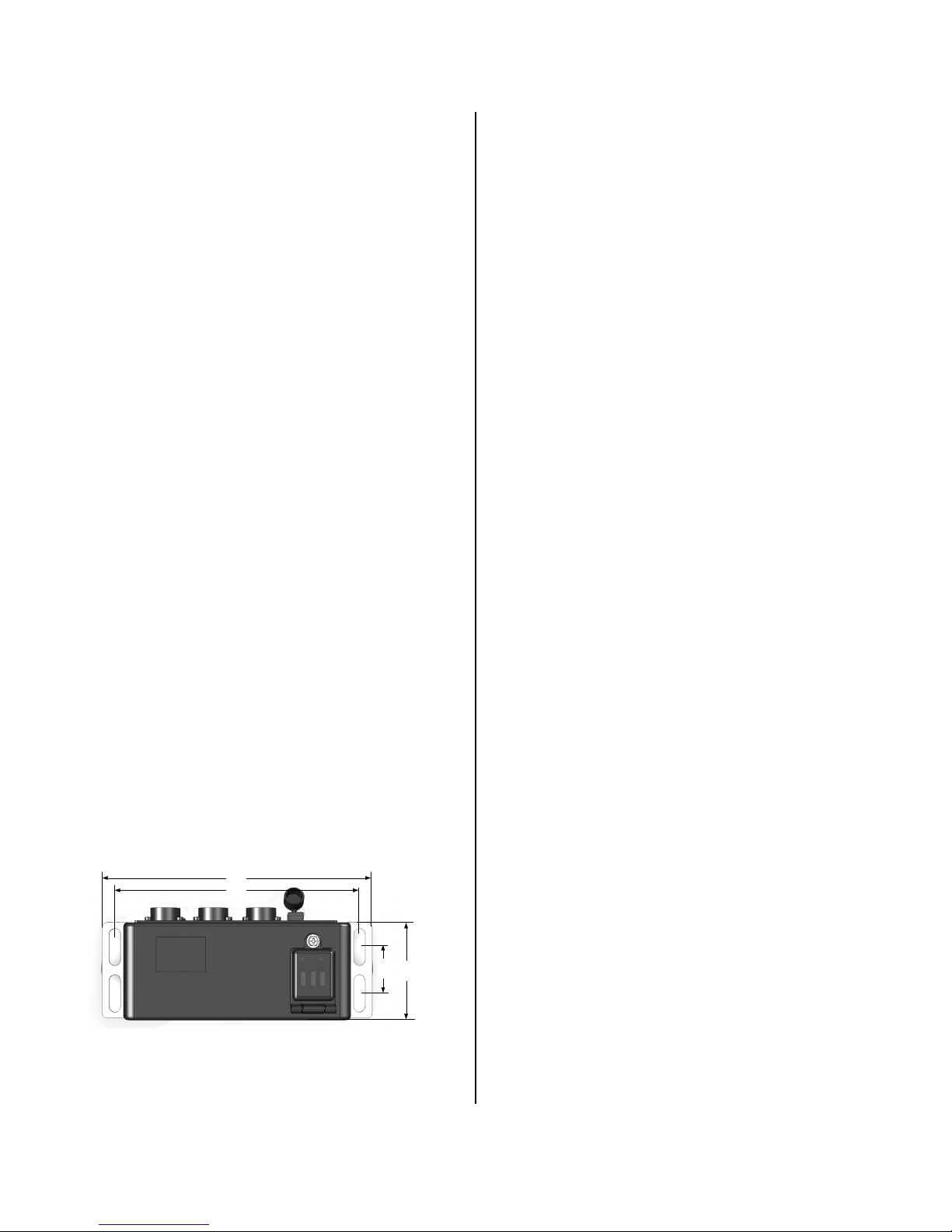
8.27"
7.48"
1. 42"
3. 36"
(CVS100XL from the top.)
4. The controller may be installed anywhere within
the cab or outside the vehicle provided you stay
within the available length of the controller to display
cable. (Installation outside requires the CVS100H or
CVS100XL controllers. Do NOT install the CVS100M
outside.) When selecting a location, make sure you
have a solid mounting surface and that the controller
will not come in contact with any of the vehicle’s
electrical circuits as shorting to the controller’s metal
enclosure can occur.
Also be certain to keep the controller and the
controller-to-display cable away from any source of
significant heat (see the Operating Temperature
specs in this manual for the safe operating
temperature range).
5. The controller-to-display cable (CVDC6MA) and
the power harness are provided with the controller.
Install and connect the controller-to-display
cable and the remote control before connecting
the power harness. The Power (red), Reverse
(blue), and Ground (black) wires on the power
harness need to be connected. The ground wire
should be connected first. To do this, simply locate a
solid chassis ground and secure the wire to it.
Second, should be the power. This should be
connected to a post ignition +11 to +32 VDC power
source. Finally, connect the reverse wire. It should
be connected to the reverse light circuit or some
other +11 to +32 VDC circuit that is only active when
the vehicle is put into reverse. When connected
properly, this allows the system to come on
automatically and display the OSD distance grid
when the vehicle is placed in reverse.
Mount the remote so that it is easily accessible to
the driver. Please consult your INTEC
Representative with any and all questions regarding
installation.
6. Secure the display in the bracket (with the
mounting knobs provided) and adjust its positioning
as needed.

© INTEC Video Systems, Inc.
Revision F May, 2013 9
The CVS100 is equipped with two status LED’s
relating to power. One for system power and the
other for the 1 Amp radar alarm output. These fuses
are located under the hinged cover on the top of the
controller.
The Power LED will be illuminated green when
power (+11 to +32 VDC) is applied to the controller.
The Power LED will not be illuminated (off) if the 2
Amp power fuse is open or “blown”.
The 2 Amp Radar fuse will be illuminated when
power is applied to the controller and off in the event
the fuse is blown.
There is also a spare 2 Amp fuse.
INTEC strongly recommends using only properly
rated fuses at all times.
In addition the CVS100 is equipped with internal
auto reset fuses for camera and display power.
These fuses are designed to open in the event of a
short in the camera, display, remote or their
associated cabling and will reset once that short has
been removed.
Camera Installation
For optimum field of view, mount the rear camera
approximately 10 feet up on the vehicle from ground
level so that the rear-most part of the vehicle is
visible at the bottom of the display screen. If this is
not possible, mount the camera in a fashion that will
give the driver the best possible view of the area
behind the vehicle while still aligning the rear-most
part of the vehicle with the bottom of the display
screen as a reference.
1. Establish a solid mounting location in the center of
the vehicle using the guidelines above. Make sure
that no part of the installation obstructs any lights or
any part of the driver's view.
2. Position the camera(s) with the mounting bracket
attached in the location where it will be mounted and
turn on the system to check the field of view (you
may have to reverse the camera’s mounting bracket
to obtain the proper angle). Be certain the field of
view of all installed cameras provides adequate and
appropriate coverage for your application.
3. Once the location and angle have been
determined, use the camera bracket or bracket
extension as a template to mark the position where
the holes will be drilled and drill the holes. Make
sure the area being drilled into is clear of all wires
and other items before you begin drilling.
4. Once the holes are drilled, install the camera
mounting bracket and extension, if required, with the
mounting bolts provided. You may need to purchase
additional hardware if the hardware provided does
not work in your application.
5. Mount the camera in the bracket with the
hardware provided and align it so that the rear-most
part of the vehicle is in line and viewable at the
bottom of the display screen.
6. It is recommended that you apply an anti-galvanic
compound to the camera mounting bolts before
installation.

© INTEC Video Systems, Inc.
Revision F May, 2013 10
Cable Installation
The following are general tips and precautions to
keep in mind while routing the cable between the
camera and controller or the controller and display.
With the exception of Molex connectors (found on
the CVU and CVXLP series cable harnesses), the
entire cable is weatherproof and can withstand
exposure to cold (down to -40 degrees F), rain,
snow, dirt, etc. If you feel the environment in which
the cable is exposed is extremely harsh, you can
route the cable through a conduit or consult INTEC
about our optional application cable harnesses for
extreme temperature or environmentally challenging
applications.
If exposed to the environment, the Molex connectors
must be weatherproofed. A simple means is to use
1-inch diameter gum interior heat shrink tubing
(available from INTEC) to cover the whole connector
assembly. This will seal and protect the connector
from direct moisture due to rain, snow, vehicle
washing, etc. Weatherproof junction boxes, properly
sealed, are another means. One should occasionally
check the seals to make sure they remain intact.
We recommend using the waterproof XL or H cables
and connectors so that heat shrinking is not
necessary.
DO NOT use electrical tape, slotted plastic conduit
or silicon only as a weatherproofing. They may
protect the connector for a short period of time but
will quickly lose their ability to keep moisture away
from the connector and pins.
Other cable installation hints include:
1) Do not attach the cable to moving vehicle parts.
2) Keep the cable at least 12 inches away from any
significant source of heat.
3) Avoid running the cable along the same side of
the chassis as the ABS wiring.
4) Route the cable where it is protected from road
debris or overhead hazards.
5) Secure the cable so that vehicle vibration and
shock do not loosen it. Tie the cable down
approximately every 12 - 18 inches. Insulated P-
clamps are recommended where appropriate.
6) Secure the cable on both sides of a pivot point
allowing enough cable to extend fully but not so
much as to cause snagging. Run the cable to avoid
getting caught in the pivot point.
7) If you have excess cable, do not coil it too tightly;
avoid crimping the cable.
8) Do not staple through the cable.
Periodic checks of the camera system and its wiring
will help spot potential trouble areas before they
result in a system failure. An excellent time to check
is when the vehicle is in for routine maintenance.
© INTEC Video Systems, Inc.
Revision F May, 2013 11
Connector Alignment
There are three types of connectors commonly used
in the camera system; Molex, Hirose, and Mil Spec.
All of which have alignment marks or keys to insure
correct alignment and proper installation.
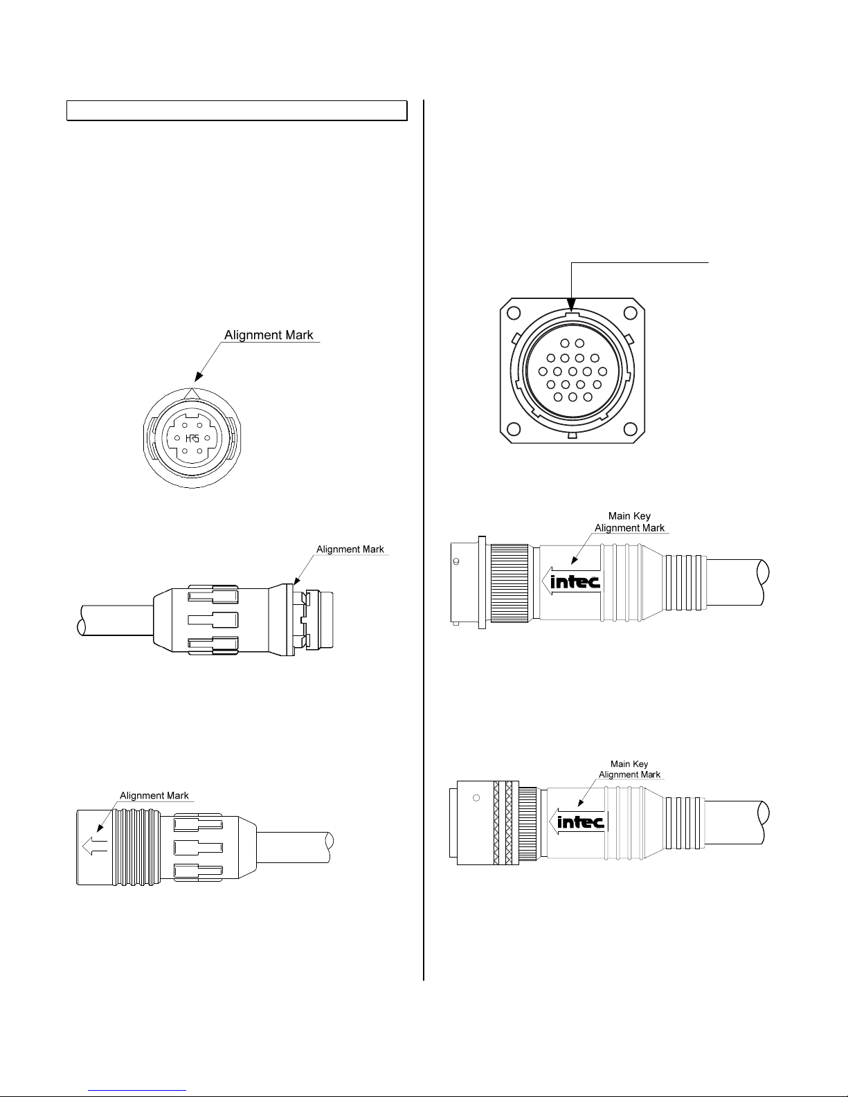
Hirose Alignment
The Hirose panel mounted connector found on the
display, controller, and certain cameras has an
alignment mark arrow on the face of the connector
as shown below. This same mark is found on the
face of the inline cable mating jack when multi-part
cable extensions are used.
Inline cable jack shown below:
When making a connection, align the arrow on the
outer shell of the mating cable connector (seen
below) with the alignment arrow on the face of the
mating connector and push until locked.
XL (Mil Spec) Alignment
The XL (Mil Spec) panel mounted connector found
on certain controllers and cameras has a 5 way
keyed alignment as shown below. This same 5 way
keyed alignment is found on the face of the inline
cable mating jack when multi-part cable extensions
are used.
Main Alignment Key
Inline cable jack shown below:
When making a connection, align the 5 keys on the
connectors and turn the outer locking ring until
locked. For XL cables with over molded back shells
the arrow with the INTEC logo is inline with the main
(top) alignment key.

© INTEC Video Systems, Inc.
Revision F May, 2013 12
Image Orientation
The orientation of the image displayed is critical to
safe vehicle operation. An object on the right side of
your vehicle needs to be seen on the right side of
the displayed image.
Orientation Requirements
Generally, if your display is facing rearwards, you
would want a Mirror image displayed from a camera
facing rearward and a True image displayed from a
camera facing forward. The image orientation of
cameras on the right or left side of a vehicle
depends on how far off of center they are facing. For
example; a camera mounted on the right side at 90º
off of the front would usually require a true image to
be displayed. But set the camera to 91º off of the
front and a mirror image may be required. Be sure to
confirm the image(s) displayed are appropriate for
your application before operating the vehicle.
How to Change Your Image
INTEC’s CVC Series cameras are set as default at
the factory to display a mirror image when used with
our CVD or CVM Series displays and monitors.
Should you need to change the default image, you
have the option of changing it at the camera or the
display (see the Operating Instructions for
information on changing the image at the display).
Note: Not all INTEC cameras can be changed in the
field; some may need to be returned to INTEC to
have the image changed. Refer to your camera’s
Operation Manual for information on your particular
camera. Always confirm proper orientation before
operating your vehicle.
Operating Instructions
Controller Operation
The CVS100 controller does not have any
independent controls. All adjustments are made via
the remote control and are dependent upon the
controller and software version used.
Refer to the displays ON-Screen Menu for
information regarding the software version installed
there.
CVR100 (Single Channel Remote)
- Manually turns the display on or places it in
standby.
- Accesses the on-screen menu.
- Continue pressing Menu to scroll through the
menu items.
- Adjusts the radar audible alert between three
available preset levels. (Active when used with a
compatible radar system)
- Increases screen brightness.
- Increases the value of a menu item
- Decreases screen brightness.
- Decreases the value of a menu item.
- Selects the external video input. (Must be set to
on before it can be selected).
© INTEC Video Systems, Inc.
Revision F May, 2013 13
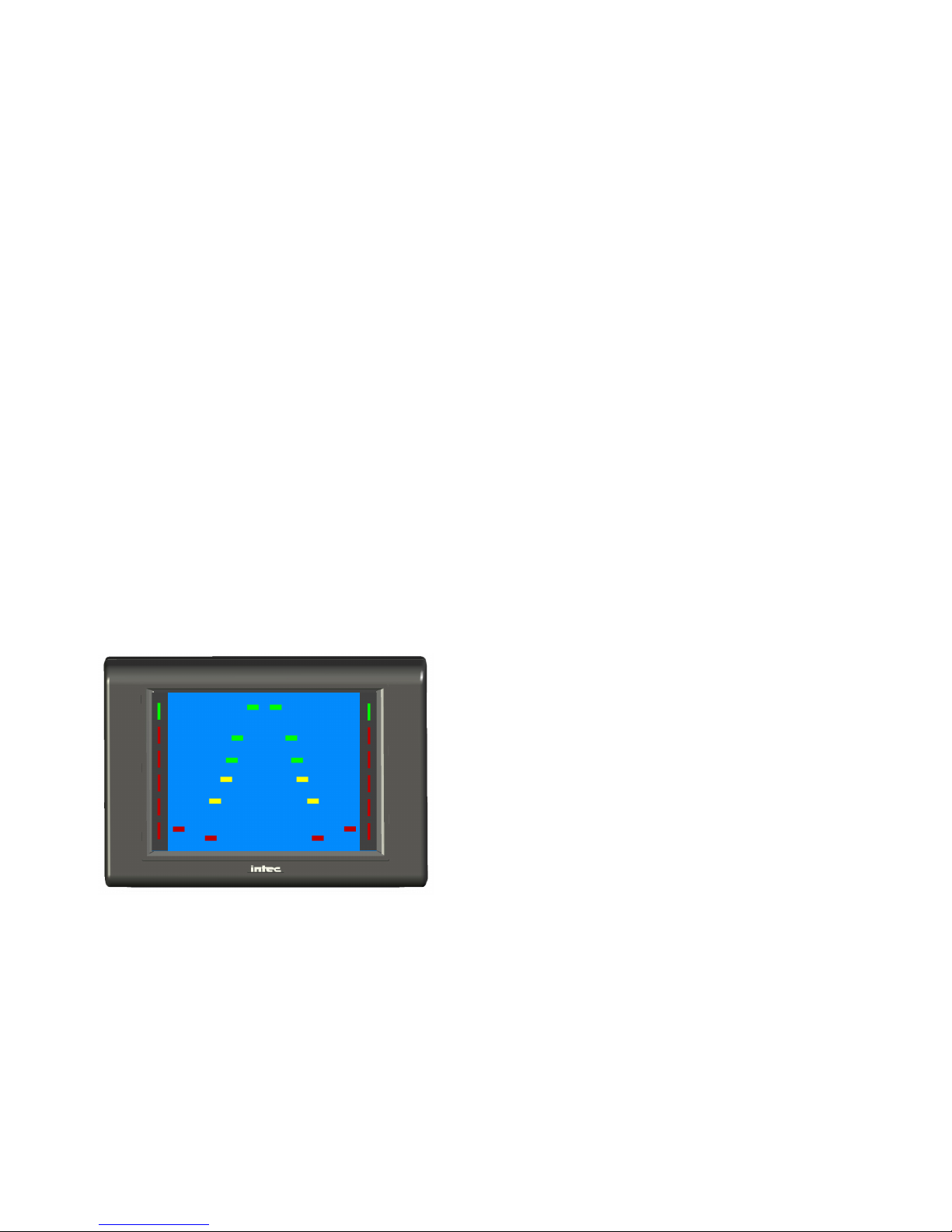
Radar Operation
CVS100M AND CVS100XL Versions Only (Radar
is NOT available in the CVS100H)
The integrated radar, when properly connected, will
send a visual alert to the Car Vision®display and an
audible alert to the Car Vision®remote when an
object is detected within its operating range. The
visual alert consists of light pipes on the left and right
sides of the display screen. When properly connected
and powered green lights at the top of the light pipes
will illuminate, indicating the radar is active. When an
object is detected in the outer most detection area,
the first of 5 red lights will illuminate starting at the top
of the light pipes, just under the green lights. As the
object gets closer to the radar sensor(s) additional
red lights will illuminate in succession from the top of
the screen to the bottom as well as start flashing and
an audible beeping will be heard through the remote.
While in reverse, the on-screen distance grid will also
flash off and on according to the detected object’s
distance from the sensor. (See figure 1)
The integrated radar will only operate when
connected via an INTEC cable to the camera
connector and the system is triggered, via the blue
wire, with a +11 to +32 VDC source.
(Figure 1)
Setting the Image Orientation in the Display
The image displayed can be set to either a REV
(Mirror) or NOR (True) image depending on the view
required. As default the image is set to REV from the
factory. Refer to the On-Screen Menu section of this
guide for further details.

© INTEC Video Systems, Inc.
Revision F May, 2013 14
On-Screen User’s Menu
Press <Menu> to access the user’s menu.
Continue pressing <Menu> to select the next line item.
At the last line item press <Menu> again to continue to the next page.
Use the up and down arrow keys to change the value.
Changes Made are automatically saved.
The user’s menu will shut off after 5 seconds of inactivity.
VOLUME Adjusts the volume level of the audio supplied by
the camera.
BRIGHT Adjusts the brightness of the LCD panel.
CONTRAST Adjusts screen contrast.
Press <Menu> to select the next line item.
At the last line item press <Menu> again to continue to the next page.
Use the up and down arrow keys to change the value.
COLOR Adjusts color level. (Only works with color
cameras.)
TINT Adjusts screen tint.
DIMMER
When set to AUTO the screen will brighten or
dim based on the ambient light around it.
When set to MAN the user controls the screen
brightness via the brightness adjustment.
Press <Menu> to select the next line item.
At the last line item press <Menu> to go back to the first page.
Use the up and down arrow keys to change the value.
RESET
Resets the user menu back to the factory default.
Highlight RST and press <MENU> again to
reset.
VER Displays the current software version for your
display.

© INTEC Video Systems, Inc.
Revision F May, 2013 15
On-Screen Installer’s Menu
Press <Menu>and the <UP> arrow keys simultaneously
to access the installer’s menu.
Continue pressing <Menu> to select the next line item.
At the last line item press <Menu> again to continue to the next page.
Use the up and down arrow keys to change the value.
Changes Made are automatically saved.
To exit place the system in Standby then turn it back on.
EXT IN Turns on/off the External video input function.
RADAR 1
Set to STD for standard radar, set to CAN for all
others.
Note: Radar 1 connects to the camera input via
an Intec cable and is only active when triggered.
ALARM Turns the Alarm Output function off and on.
Press <Menu> to select the next line item.
At the last line item press <Menu> again to
continue back to the first page.
Use the up and down arrow keys to change the value.
LCD 1
“REV” Displays the image from an INTEC
camera on the screen as a Mirror image.
“NOR” Displays the image from an INTEC
camera on the screen as a True image.
RESET
Resets the installer and user menus back to the
factory default.
Highlight RST and press <MENU> again to
reset.
VER Displays the current software version for your
display.

© INTEC Video Systems, Inc.
Revision F May, 2013 16
Troubleshooting and Maintenance
Troubleshooting
Display shows a blue screen:
Check the cables for obvious damage (i.e. cuts,
crimping) and the connectors for corrosion or pin
damage. Make sure connectors are securely
connected and free of debris.
If spares are available, swap out one item at a time;
the camera, controller and associated cabling.
Display doesn’t light up – dark screen:
Check the red and black wires at the controller to
make sure they are properly connected to the
vehicle power and ground. See if proper voltage is
reaching the controller.
See if the fuses on the controller are okay. If not,
replace with new fuses. The green LED on the
controller will be illuminated if the individual power
circuit is functioning properly. (See specification
section of the controllers operation guide for the
proper fuse rating).
Make sure connectors are securely connected and
free of debris. Check the cable for obvious damage.
There should be no continuity between any of the
wires inside the cable. If shorting has occurred, the
display and controller should always be returned for
service and the cable replaced.
Picture is blurry, out of focus or distorted:
Check the camera and clean any dirt, dust or
moisture found on the outside glass lens cover. If
any moisture is visible on the inside of the
camera, remove and return the camera to INTEC
for service.
Adjust display controls (i.e. brightness and contrasts)
to see if picture clears up.
Check voltage on the red power wire to see if
sufficient power is reaching the controller. Low
voltage may cause the picture to blur or darken.
I’ve experienced a short in my system and after
correcting it my image is reversed:
After a short, it may be necessary to reset the
display software. (Refer to the On-Screen Menu
section of this guide for instructions on resetting the
menu).
A continuous tone is heard through the remote
and I have no remote control function:
Turn the vehicle power off for 10 seconds and turn it
back on.
Check to make sure the remote control is connected
properly.
Preventative Maintenance
The most effective way of reducing camera system
failure is regular preventative maintenance. At least
once every two weeks and/or every time the vehicle
is in for its scheduled maintenance is recommended.
Although it would be difficult to cover every possible
scenario, the following are some examples to look
for:
1. Physical damage to the camera. Examples:
cracked camera glass, bent front covers, damaged
casing or brackets.
2. Dirt or moisture on the camera’s glass. Cleaning
the camera’s glass should be done with a clean, soft
cloth to prevent scratching. For excessive dirt build
up, you may need to rinse the camera glass with
water or glass cleaner first.
3. Scratched camera glass. Excessive scratches on
the cameras glass can distort the image. Cameras
with scratched glass should be returned to INTEC
for service.
4. Moisture behind the camera glass.
If this is found, simply removing the cover and wiping
off the glass will not solve the problem. Repairing
the source of where the moisture is coming into the
camera is the only way to prevent it from happening
again. The camera should be returned to INTEC for
service.
5. Damage to the cable and the connector seal. This
includes the main cable as well as the camera and
monitor pigtails. Examples: Cuts or abrasions in the
cable, cuts in the connector seal or a connector seal
that has come loose.
Note: Connector sealing is not required in the XL
and Hirose Camera Series.

© INTEC Video Systems, Inc.
Revision F May, 2013 17
6. Dirt on the display. Cleaning the display should be
done with a clean, soft cloth to prevent scratching.
For excessive dirt build up you can lightly dampen
your cloth with water or glass cleaner.
7. Physical damage to the display, remote or
controller and its power conductors. Examples:
Cracked display casing, missing parts, exposed
power wires.
8. Equipment that has come loose. Examples:
Cables that are not secure, cameras, displays, and
their brackets which may have come loose.
9. Educating the drivers on reporting minor problems
before they become major problems. Example:
Unreported moisture intrusion can result in the
camera being damaged beyond repair.
By taking a few minutes to inspect the camera
system on a regular basis you will ensure long-term
reliability with minimum cost and down time.
Periodic checks of the camera system components
and wiring will help spot potential trouble areas
before they result in a system failure. An excellent
time to check is each time the vehicle is in for routine
maintenance.
How to get Service
If none of the troubleshooting suggestions in this
manual solve your problem, you may need to return
the product to INTEC for service.
First, call INTEC’s Customer Service Department at
either our Western Office (800) 468-3254 or our
Eastern Office (800) 522-5989.
Explain the problem to the customer service
representative. The representative will check to see
if you tried the in-field adjustments and may offer
alternative solutions for you to try. If these solutions
don’t work, you may be asked to send some or all of
your system to INTEC.
A Return Materials Authorization (RMA) number will
be issued. Refer to this number during any future
contact with INTEC concerning this service.
Please have the following information available to
give to the customer service representative:
1. The product model number and serial
number.
2. A description of the problem.
3. The type of vehicle on which the product
is installed.
4. Your name, address and phone number.
5. The address, phone number and contact
person of where we should return the
product after it is repaired if this is different
than above.
6. Any special requests (i.e. repair
estimates, expedite return shipment).
7. Proof of purchase.
Send the product, prepaid and insured to the
closest INTEC office:
Western U.S. and Canada:
INTEC Video Systems, Inc.
Customer Service Department
23301 Vista Grande
Laguna Hills, CA 92653
Attn:RMA_______________
Eastern U.S. and Canada:
INTEC Video Systems, Inc.
Customer Service Department
4256 State Route 51 North
Belle Vernon, PA 15012
Attn:RMA_______________
Make sure to package your Car Vision®unit carefully
to avoid any damage during shipping. If possible,
use the original carton and packaging materials.
Our warranty does not cover loss or damage in
transit.
Products shipped to INTEC without an RMA number
may not be accepted or may result in a delay in
service. Make sure your name, address and phone
number appear somewhere on the shipping
container or paperwork enclosed within.
You may also call to inquire about any installation
issues or concerns.

© INTEC Video Systems, Inc.
Revision F May, 2013 18
Additional Information
Warranty
INTEC warrants the Car Vision® Controller, Model
CVS100, when purchased new, to be free from
defects in material and craftsmanship. INTEC will
repair or replace, at INTEC’s sole option and without
charge, any part which under normal and proper use
is found to be defective within the effective period of
this warranty. The effective period of this warranty is
five (5) year for the CVS100M, five (5) years for the
CVS100H and eight (8) years for the CVS100XL
from the original date of purchase from INTEC. This
warranty is void and does not cover product that has
been lost or damaged in shipment, subjected to
misuse, abuse, tampering, improper installation, use
on improper voltage or current, use contrary to
operating instructions, or disassembly, repair, or
alteration by anyone other than INTEC or an INTEC
authorized service agent.
IN NO EVENT SHALL INTEC BE LIABLE FOR SPECIAL,
INDIRECT, INCIDENTAL OR CONSEQUENTIAL
DAMAGES, OR EXPENSES. THE SOLE LIABILITY OF
INTEC SHALL BE DISCHARGED BY REPAIRING OR
REPLACING ANY PART OR PARTS WHICH MAY
PROVE DEFECTIVE UNDER NORMAL AND PROPER
USE WITHIN THE CONDITIONS AND EFFECTIVE
PERIOD OF THIS WARRANTY, PROVIDED THE
PRODUCT IS RETURNED TO INTEC, DELIVERY
PREPAID AND INSURED, IN ACCORDANCE WITH THE
INSTRUCTIONS SET FORTH IN THE SERVICE
INFORMATION SECTION OF THIS GUIDE.
THERE SHALL BE NO OTHER WARRANTIES,
EXPRESSED OR IMPLIED, INCLUDING ANY IMPLIED
WARRANTY OF MERCHANTABILITY OR FITNESS FOR
A PARTICULAR PURPOSE OR ANY OTHER
OBLIGATION ON THE PART OF INTEC.
This warranty gives you specific legal rights, and you
may also have other rights that vary from state to
state. You should contact the appropriate state
agency to find out what these rights might be.
Return of the Owner Registration Card is not
required for warranty coverage. However, it will
insure that you are notified with product update
information. It will also help INTEC to better serve
you by answering some important marketing
questions on the Card. Any information you provide
on the Card is for INTEC’s internal use only. Our
customer list is not sold or given to any other
organizations unless required under State or Federal
laws.
Thank you for your business.
INTEC Offices
Headquarters
Western Regional Sales and Service
23301 Vista Grande
Laguna Hills, California 92653 USA
USA and Canada
Tel: 800-468-3254
Fax: 949-859-3178
International
Tel: 949-859-3800
Fax: 949-859-3178
Eastern Regional Sales and Service
4256 State Route 51 North
Belle Vernon, Pennsylvania 15012
USA and Canada
Tel: 800-522-5989
Fax: 724-929-6590
International
Tel: 724-929-5500
Fax: 724-929-6590
www.intecvideo.com

© INTEC Video Systems, Inc.
Revision F May, 2013 19
Owner Registration
Model CVS100
Name:
Address:
City: State: Zip:
Serial Number:
(Located on the top of the controller)
Purchased from:
Address:
City: State: Zip:
Date of Purchase: Date of Installation:
Installed on what type of vehicle: Manufacturer:
Model: Size (length):
Installed by: Manufacturer __________ Dealer __________
Self __________ Other service shop __________
How did you hear about the INTEC Car Vision®System? INTEC _____ Distributor/Dealer _____
Trade Show _____ Magazine Ad _____ Article ______ Other equipment user _____ Friend _____
Previous experience _______ Web Search______ Other
What industry magazines do you read?
What trade shows do you attend?
Why did you decide to purchase the Car Vision®System?
How can we improve our product or service?
Mail Registration to: INTEC Video Systems, Inc., 23301 Vista Grande, Laguna Hills, CA 92653. You may also fax
it to us at (949) 859-3178 or complete it online by visiting www.intecvideo.com/registration.pdf
Table of contents


