Integral LED ILBTASE057 User manual

Integral Product Code Dimensions Net Wt.
ILBTASE057 149 x 36.4 x 28 mm 0.13Kg
EN
INSTALLATION INSTRUCTION
for Integral LED Batten Pir Sensor
3 Year Warranty
129.6mm
149mm
28mm
36.4mm
17mm
Thank you for purchasing an INTEGRAL LED product. When installed correctly this unit will provide years
of service. For support or warranty information please see integral-led.com.
Important Details – Please read prior to installation
Always turn o circuit power at the distribution unit before installation and maintenance. Please ensure
that the power cannot be connected inadvertently.
• ThePIR(passiveInfrared)sensorprovidesautomaticcontroloflightingloads.Itisspecicallydesignedtobe
mountedontoabattenstyleluminaire.
• ThedetectorwilldetectmovementusingaPIRsensorandturnthebattenon.Whenanareaisnolonger
occupied,thebattenwillswitchoafterapre-settime-outperiod.
• Thedetectorcanswitchincandescent,uorescent,compactuorescentandLEDlighting.
• AselectionofxingwashersaresuppliedtoaidxingtoavarietyofbattenswithanM20opening.
• Itcanbeinstalledto1-10Venableddimmingandnon-dimmingluminaires(on/oonly).
• The unit consists of:
• PIRSensor–detectsmovementwithinthedetectionareatoenablecontroloflightswitching
• IR Receiver – receives control and set up commands from the infrared handset
• Light Level Sensor – measures the light level in the detection area
• Status LED
• Redashwhenvalidcommandisreceived
• Redashwhenmovementisdetected
• Range(g2.)
Installation (Fig 3.)
1. For optimal operation:
• Ensurethelensisshieldedasmuchaspossiblefromthelightsourceandadjacentlightsources
• Avoid direct sunlight
• Keepawayfromheatingandventilationunits
2. Theproductisdesignedtobemountedtotheoutsideoftheluminaireviaa20mmdiameteraccesshole.The
M20screwthreadsuppliedwashersandlockingnutwillsecuretheproductinplace.Duringinstallationcare
mustbetakennottograbthelenswhentighteningthelockingnuts.Donotovertightenandavoidcross
threading or damaging the thread.
3. EnsurethattheSiliconewasherand/ortheIPspacerareusedtoensureIPrating.
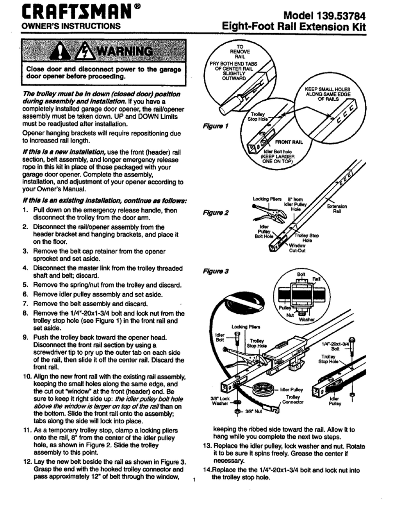
4. Notes: Use the 4 spacers where the luminaire housing has a draft angle.
Fixing Kit (Fig 4.)
1. INCLUDES STANDARD 20MM DIAMETER HOLES AS ADVISED. HOWEVER, SENSOR DOES NOT NECESSARILY
REQUIRE STRAIGHT SIDED HOLES AS SHOWN IN FIGURE 4
2. 5degreewashersaretobeusedwithproductwallsthathaveadraftangle.Useofthewasherswillensurethe
productliesinsamehorizontalplainasbatten.FortheILBTCXXXrangeofintegralproductsthesearenotrequired

Wiring Instructions (Fig 5.)
1. Connectionsshownaretypicalfor1-10Vdimmableandnon-dimmablebattenssuppliedbyIntegral.
2. ****Supply-WiringcoloursshouldbeEuropeanBrownliveandBlueNeutralmustmakeanotethatsensor
cabledshouldbesleevedwiththeappropriatecolourforinstallation***
3. The black and white sensor wires should be appropriately sleeved with brown (Live) and blue (neutral)
sleeving during installation.
Operation using hand controller (Fig 6.)
1. To use the hand controller to program luminaires, point the hand controller at the installed PIR sensor
receiver (under the domed PIR sensor lens).
2. NOTE: Step down lighting and dimming options are only available with products with 1-10V Dimming
enableddrivers.
3. ON/OFF MODE BUTTON:ToggletheLAMPcontinuallyon/o.
4. RESET MODE BUTTON:(ONE-TOUCHMODE)
Defaultsettings:
5. AUTO MODE BUTTON:PressingAutomodebuttonenablesthesensorwiththelast-programmedparameters
beforeeitherON/OFF,RESETorMmodebuttonswerepressed.
6. NotethattheparameterscanstillbeadjustedinAUTOMODE.
7. AUTO MODE SETTINGS PROGRAMMING EXAMPLE:Settheparametersfor:sensitivity50%,holdtime10
seconds,lux,dimminglevel20%,dimmingtime1min.
a) STEP:presstheautobutton. LEDwillashoncetoconrm.
b) STEP:pressthesensitivitybutton50%. LEDwillashoncetoconrm.
c) STEP:pressholdtime10sbuttons. LEDwillashoncetoconrm.
d) STEP:pressluxbutton. LEDwillashoncetoconrm.
e) STEP:pressdimminglevelbutton20%. LEDwillashoncetoconrm.
f) STEP:dimmingtime1minbutton. LEDwillashoncetoconrm.
8. To check settings, move across sensor to make the LAMP turn on with 100% brightness. After 10s with
nomovementtheLAMPshouldgofrom100%to20%brightness.
ToggleLAMP
continuallyon/o
Initiate a 2 second sensor test
Standbyanddaylightsensor
aredisabledduringthetest.
Store/setparameters
inmemory
EnableAUTOMODEusing
latest stored settings
Aonetouchbutton.
Defaultsettingsare:
100%motionsensitivity
10 second hold time
20%standbylightlevel
24hourstandby-nevero
Setmotiondetectionsensitivity Set the hold time during which
triggering is ignored. Refers to the
timeperiodthelampremainsat100%
illumination after no motion detected.
Use this to override
previous lux setting. This
allowsdaylightthreshold
tobesetforprevailing
light conditions
Usethesebuttonstosetthedaylight
threshold 10lux, 30lux, 50lux or
fordaylightsensordisabled
Setthelightleveloutputforstandby,
Referstothelowlightlevelyouwould
liketohaveaftertheholdtimeinthe
absenceofpeople
Setthestandbyperiod.
24hourisnevero.
Refers to the time period
the lamp remains at a
lowlightlevelbeforeit
completelyswitchesoin
theabsenceofpeople.

9. Note1:IftheLAMPdoesnotdimfrom100%to20%,eitherthesensitivityistoohighormovementwaswithin10s.
10. Note2:Pushingabuttonatanytime,theLEDlightwallashoncetoconrmreception.
M (Memory) MODE:
11. StoreparametersinthehandcontrollerandPIRsensor.Youwillrstprogramthehandcontrollertostore
theparametersandthentransmitthemtothePIRsensorunitontheLAMP.
12. EXAMPLE:Settheparametersfor:sensitivity50%,holdtime10seconds,lux,dimminglevel20%,dimming
time 1mm.
a. Clear the memory:
i. Checkwhetheranyparametersarestored:
ii. Push the M button once. If parameters have been stored, then the LED will ash once otherwise no
parameters are stored
b. Clear the memory:
i. PresstheMbuttonfor3secondsuntiltheLEDcontinuallyashes.Checkmemorywasclearedasabovein
gurea)
c. Record the memory:
i. STEP:presstheMbuttonfor3secondsuntiltheledcomeson
ii. STEP:pushtheautobutton,ledwillashoncetoconrm
iii. STEP:presstheautobutton,ledwillashoncetoconrm
iv. STEP:pressthesensitivity50%,ledwillashoncetoconrm
v. STEP:presstheholdtimebutton10seconds,ledwillashoncetoconrm
vi. STEP:pushlux,ledwillashoncetoconrm
vii. STEP:pressdimminglevel20%,ledwillashoncetoconrm
viii. STEP:pressdimmingtime1min,ledwillashoncetoconrm
ix. STEP:presstheMbuttonagaintorecordthememoryintothehandcontroller
x. STEP: point the hand controller at the installed PIR sensor and press the M button again to send
yourprogrammingtothePIRsensor
13. TosendtheprogrammingtoanotherLAMPpointitattheinstalledPIRsensorandpresstheMbuttonagain.
General Guidelines for installation:
1. This product must be installed by a competent qualied electrician in accordance with the instructions
providedand incompliancewithrecognised electricalandsafetyregulationsrelevanttothe countryitis
beinginstalled.
2. Forthecorrectpolaritypleasesee“WiringConnection”.
3. Nouserserviceableparts.
Warranty:
Thisunitcarriesa3yearwarrantyfromthedateofpurchase,providingthatithasbeeninstalledcorrectlyand
notmodiedinanyway.Shouldafaultoccur,pleasecontacttheoriginalplaceofpurchase.
Specication:
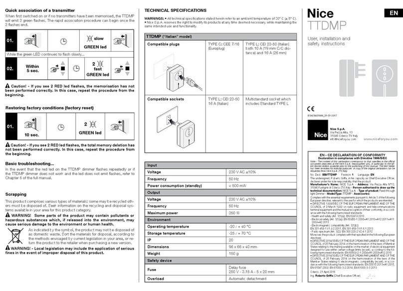
PowerSupply:220-240VAC,50/60Hz OperatingTemperature0°Cto+50°C
StorageTemperature:-20to+50°C IPRating:IP65
ConstructionMaterial:Polycarbonate
Important Notes:
• Operatingandluminairemustbewithinratedtemperatureavoidingextremehumidity
• Operationmustbewithinratedinputvoltage
• Keepawayfromstrongelectromagneticradiationsourcesandprotectfromlightningstrike
• Should the unit malfunction, return to distributor or reseller. No user serviceable parts inside. Do not
disassembleorattempttorepairoutsideoftheinstallationguidelines
• Donotinstalltoaluminaireifthehousing/diuserisfoundtobebroken
WASTE ELECTRICAL PRODUCTS SHOULD NOT BE DISPOSED OF WITH HOUSEHOLD WASTE. PLEASE
RECYCLE WHERE FACILITIES EXIST. CHECK WITH YOUR LOCAL AUTHORITY FOR RECYCLING ADVICE.

Warranty/Technical and
contact information
are all available at
www.integral-led.com
Integral LED is a division
of Integral Memory plc:
Unit 6, Iron Bridge Close,
Iron Bridge Business Park,
London, NW10 0UF, UK
IP65
IP65 housing
IR hand controller
M20cable
entry PIR Lens covering:
-PIRsensor
-Lightlevelsensor
-IRreceiver
Note.Keytobe
at top of sensor
Fig.01 Fig.02
Fig.03 Fig.04
Fig.05 Fig.06
2.8m
14m
ON
OFF
ON
OFF
Walk across
Height Range Diameter
7m 16m
2.8m 14m
Walk towards
Height Range Diameter
7m 10m
2.8m 5m
Silicone washer
M20nut
5º washer (optional)
5º washer (optional)
Power
Black
Black
White
Sensor
Sensor
White
LIVE(Brown)
Violet&Grey-noconnection
9mm
Ø20mm
Ø20mm
2mm
17mm
17mm
+(Violet)
-(Grey)
LIVEOUT(Red)
LIVEOUT(Red)
White
DIM+
LED+
LED+
LED-
LED-
DIM-
ACL
ACN
LED
Driver
Do not connect Dim - to LED - or Dim+ to LED+
LIVE(Brown)
NEUTRAL (Blue)
NEUTRAL (Blue)
NEUTRAL(White/Blue)
Power
Non - Dimming Driver
Dimming Driver
N
L
L
E
D
Componets Mounting hole without key
Mounting hole with key
Parts
1 x Silicone
washer
1 x 5º washer
1 x 5º spacer
1xM20nut
