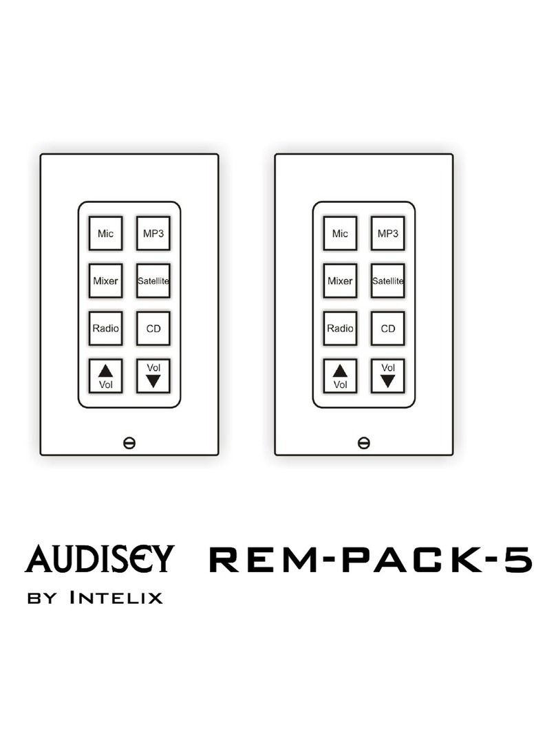
Intelix Audisey REM-PACK-8 User manual

Audisey REM-PACK-8
by Intelix

Intelix REM-PACK-8 Installation Manual
2 www.intelix.com
Table of Contents
Overview............................................................................................. 3
REM-PACK-8 Contents ..................................................................................................3
Wiring the REM-PACK-8 .................................................................. 4
Determing the Cabling Schematic...................................................................................4
Wiring with Twisted Pair and 18 Gauge Cable .............................................................5
Preparing the Serial Cable ........................................................................................... 6, 9
Wiring with Twisted Pair Cable.................................................................................... 10
Programming the REM-PACK-8 Remotes.......................................15
Installing Athena Designer Software ........................................................................... 16
Customizing the Physical Remote Control Buttons.................................................. 18
Estabishing Communication with the Matrix............................................................. 19
Technical Specifications ...................................................................20
Troubleshooting................................................................................21
Warranty ............................................................................................22
Copyright 2008 Intelix LLC.
Design with Intelligence

Intelix REM-PACK-8 Installation Manual
www.intelix.com
3
Overview
Designed for the Intelix Audisey Athena matrix mixer/amplifier, Intelix Remote
Control Packs are complete, pre-programmed remote control systems designed
for quick, easy setup and operation.
Sold in packages, Intelix Remote Control Packs are available in packages of 3,
4, 5, 6, 8, 12, and 16 remote controls. Each package includes all of the wiring
accessories, IR to serial control modules, and push-button remote controls
needed for 2-16 independent zones.
Each remote control mounts into a standard single-gang wallbox and features
visual and auditory feedback, multiple label options, and password protection.
Design with Intelix and Design with Intelligence.
REM-PACK-8 Contents
Before installing the Intelix REM-PACK-8, please ensure you
received all the necessary components. These components may be
located in several packages.
(8) CB-1000 remote controls
(1) ION-LT IR/serial controller
(8) CW-TB wiring blocks
(9) 12VDC power supplies
(8) 24-sheet CB-1000 button caps
(8) single gang decora plates
(8) 6’ IR cables
(8) IR breakout cables
(1) Athena Designer Software CD

Intelix REM-PACK-8 Installation Manual
4 www.intelix.com
Wiring the Intelix REM-PACK-8
Determining the Cabling Schematic
Before installing the Intelix REM-PACK-8, determine which cabling schematic
best fits your application.
Cabling Schematic A (pictured below; top) allows the remote controls to be
located up to 630 feet from the controlled hardware (typically an Intelix Audisey
Athena matrix mixer/amplifier).
Cabling Schematic B (pictured below; bottom) allows the remote controls to be
located up to 230 feet from the controlled hardware.
The main advantage of wiring according to Cabling Schematic A is system
distance—because only data is being transmitted over the twisted pair cable, the
remotes may be located up to 630 feet from the controlled hardware. The main
disadvantage is having to run both twisted pair cabling (for control) and 18
gauge cabling (for power).
The main advantage of wiring according to Cabling Schematic B is cabling
ease—both power and data are being sent over a single twisted pair cable. The
main disadvantage is distance—you are limited to 230 feet of distance between
the remotes and controlled hardware.

Intelix REM-PACK-8 Installation Manual
www.intelix.com
5
Wiring with Twisted Pair and 18 Gauge Cable (Cabling
Schematic A)
When wiring with twisted pair cable and 18 gauge cable, please follow the steps
below.
Wiring the Physical Remotes
The REM-PACK-8 may be wired in several different configurations. The
following steps detail the most common configuration.
1) Open the REM-PACK-8 package(s) and verify you have all of the
components listed on page 3.
2) Noting the number of the CB-1000 remote control (each remote
control’s package is labeled 1, 2, 3, 4, 5, 6, 7, or 8), remove the
remote from its packaging. You will need to know the number of
each CB-1000 for programming.
3) Determine the single-gang electrical wallbox the CB-1000 will be
installed in. Verify twisted pair and 18 gauge cable are present.
Multiple runs of twisted pair and 18 gauge cable may be present if
IR/control and power are to be daisy-chained.
4) Terminate one pair (two conductors) of the twisted pair cable to
the three conductor phoenix-style wiring block. One conductor
should be in the far left (-) slot and one conductor should be in the
far right (+) slot. Connect the wiring block to the physical CB-
1000.
5) Terminate two conductors of the 18 gauge cable to the two
conductor phoenix-style wiring block. One conductor should be in
the top (-) slot and one conductor should be in the bottom (+) slot.
Connect the wiring block to the physical remote. (Multiple 18
gauge cables may be terminated to the phoenix-style wiring block
if the remote controls are to be daisy-chained).
Note: The CB-1000 is powered by a DC power supply. Polarity
is critical at the power supply and all the CB-1000 locations.
6) If remote programming and function have been determined, select
and replace the remote control’s button caps (see page 18).
7) Secure the remote control to the single-gang electrical wallbox
with the two included mounting screws.
8) Secure a decora plate over the remote control. Your remote control
is now installed.
9) Repeat steps 2-8 for each subsequent remote control.

Intelix REM-PACK-8 Installation Manual
6 www.intelix.com
Connecting Data
The following steps detail connecting data to the remote controls once they are
wired and mounted in the electrical wallbox.
1) Open the ION-LT IR/serial controller packaging and mount the
ION-LT in a permanent location within 15 feet of the Intelix
Audisey Athena matrix mixer/amplifier or other serially controlled
hardware.
2) Connect the ION-LT to the controlled hardware with a prepared
serial cable (purchased separately).
¾Pin 2 on the serial cable (RX) should be connected
to the phoenix-style style connecter conductor 2
(TX) on the ION-LT.
¾Pin 3 on the serial cable (TX) should be connected
to the phoenix-style style connecter conductor 1
(RX) on the ION-LT.
¾Pin 5 on the serial cable (GND) should be
connected to the phoenix-style style connecter
conductor 3 (GND) on the ION-LT.
3) Mount a CW-TB wiring block (found in each of the CB-1000
remote control packages) in a permanent location within 15 feet of
the ION-LT.
Preparing the Serial Cable
The ION-LT transmits serial control signals via a three
conductor phoenix-style wiring block. To connect to the
most serially controlled hardware (including the Intelix
Audisey Athena), you must create a custom cable with a
three conductor wiring block on one end and a standard 9-
p
in RS232 connector on the other end. To create this cable,
follow the steps below:
1) Obtain a three conductor cable (15’ or less total
length) and a 9-pin serial (RS232) connector (pictured
below).
2) Solder the cables conductors to pins 2, 3, and 5. You
should now have a cable with a serial connector on
one end and three bare wires on the other. The bare
wires will terminate into the phoenix-style wiring
block on the ION-LT.

Intelix REM-PACK-8 Installation Manual
www.intelix.com
7
4) Connect the CW-TB to the ION-LT with an IR (1/8” stereo mini)
cable.
5) Determine which twisted pair cable is connected to the CB-1000
remote controls. Using the cable, connect the (+) conductor on the
remote to the (+) conductor on the CW-TB. Connect the (-)
conductor on the remote to the (-) conductor on the CW-TB. Your
system should now be fully connected: the CB-1000 remote
controls should be connected to the CW-TB, the CW-TB should be
connected to the ION-LT, and the ION-LT should be connected to
the controlled hardware.
6) Optional: The CB-1000 remote controls may be chained in various
manners. In most applications, an RJ45 bridge adaptor, such as the
Intelix Comet-BA11 or Comet-BA4, is used (sold separately). The
bridge adaptor splits an RJ45-terminated cable to multiple outputs
and is installed between the CW-TB and the CB-1000 remote
controls. Alternatively, multiple conductors of twisted pair cable
may be terminated to each remote, effectively daisy-chaining them.

Intelix REM-PACK-8 Installation Manual
8 www.intelix.com
Connecting Power
The following steps detail connecting power to the REM-PACK-8 system.
1) Using a CW-TB from one of the CB-1000 remote control
packages, connect the two conductor 18 gauge cable to the four
conductor phoenix-style wiring block. The conductor connected to
the (-) block on the remote controls should be connected to the (-)
block on the CW-TB. The conductor connected to the (+) block on
the remote controls should be connected to the (+) block on the
CW-TB. Connect the wiring block to the physical CW-TB.
Warning
Do not reverse power on the CW-TB and CB-1000 remote
controls. The system does not provide diode protection.

Intelix REM-PACK-8 Installation Manual
www.intelix.com
9
2) Connect a 12VDC power supply to the Main Power input on the
CW-TB.
3) Plug in the power supply.
4) The remote controls are now powered and should illuminate.
5) Next, connect a 12VDC power supply to the ION-LT located near
the controlled hardware.
6) Plug in the power supply.
7) The ION-LT is now powered and the power LED should
illuminate.

Intelix REM-PACK-8 Installation Manual
10 www.intelix.com
Wiring with Twisted Pair Cable (Cabling Schematic B)
When wiring with only twisted pair cable, please follow the steps below.
Wiring the Physical Remotes
The REM-PACK-8 may be wired in several different configurations. The
following steps detail the most common configuration.
1) Open the REM-PACK-8 package(s) and verify you have all of the
components listed on page 3.
2) Noting the number of the CB-1000 remote control (each remote
control’s package is labeled 1, 2, 3, 4, 5, 6, 7, or 8), remove the
remote from its packaging. You will need to know the number of
each CB-1000 for programming.
3) Determine the single-gang electrical wallbox the CB-1000 will be
installed in. Verify twisted pair cable is present.
4) Terminate one pair (two conductors) of the twisted pair cable to
the three conductor phoenix-style wiring block. One conductor
should be in the far left (-) slot and one conductor should be in the
far right (+) slot. Connect the wiring block to the physical CB-
1000.
5) Terminate a second pair (two conductors) of the twisted pair cable
to the two conductor phoenix-style wiring block. One conductor
should be in the top (-) slot and one conductor should be in the
bottom (+) slot. Connect the wiring block to the physical CB-1000.
6) Two pairs (four conductors) of the twisted pair cable will be
unused; twist these conductors around the cable housing.
7) If remote programming and function have been determined, select
and replace the remote control’s button caps (see page 18).
8) Secure the remote control to the single-gang electrical wallbox
with the two included mounting screws.
9) Secure a decora plate over the CB-1000. Your remote control is
now installed.
10) Repeat steps 2-8 for each subsequent remote control.

Intelix REM-PACK-8 Installation Manual
www.intelix.com
11
Connecting Data
The following steps detail connecting data to the remote controls once they are
wired and mounted in the electrical wallbox.
1) Open the ION-LT IR/serial controller packaging and mount the
ION-LT in a permanent location within 15 feet of the Intelix
Audisey Athena matrix mixer/amplifier or other serially controlled
hardware.
2) Connect the ION-LT to the controlled hardware with a prepared
serial cable (purchased separately).
¾Pin 2 on the serial cable (RX) should be connected
to the phoenix-style style connecter conductor 2
(TX) on the ION-LT.
¾Pin 3 on the serial cable (TX) should be connected
to the phoenix-style style connecter conductor 1
(RX) on the ION-LT.
¾Pin 5 on the serial cable (GND) should be
connected to the phoenix-style style connecter
conductor 3 (GND) on the ION-LT.
3) Mount a CW-TB wiring block (found in each of the CB-1000
remote control packages) in a permanent location within 15 feet of
the ION-LT.
Preparing the Serial Cable
The ION-LT transmits serial control signals via a three conductor
phoenix-style wiring block. To connect to the most serially
controlled hardware (including the Intelix Audisey Athena), you
must create a custom cable with a three conductor wiring block
on one end and a standard 9-
p
in RS232 connector on the other
end. To create this cable, follow the steps below:
3) Obtain a three conductor ca
b
le (15’ or less total length)
and a 9-pin serial (RS232) connector (pictured below).
4) Solder the cables conductors to pins 2, 3, and 5. You
should now have a cable with a serial connector on one
end and three bare wires on the other. The bare wires will
terminate into the phoenix-style wiring block on the ION-
LT.

Intelix REM-PACK-8 Installation Manual
12 www.intelix.com
7) Connect the CW-TB to the ION-LT with an IR (1/8” stereo mini)
cable.
4) Determine which twisted pair cable is connected to the CB-1000
remote controls. It is imperative you determine which conductors
are terminated to the remote control. In most twisted pair cables,
these conductors will be color-coded. Using the cable:
i. Connect the (+) power conductor on the CB-1000
remote to the (+) power conductor on the CW-TB.
ii. Connect the (-) power conductor on the CB-1000
remote to the (-) power conductor on the CW-TB.
iii. Connect the (+) IR conductor on the CB-1000 remote
to the (+) IR conductor on the CW-TB.
iv. Connect the (-) IR conductor on the CB-1000 remote
to the (-) IR conductor on the CW-TB.
Your system should now be fully connected: the CB-1000 remote
controls should be connected to the CW-TB, the CW-TB should be
connected to the ION-LT, and the ION-LT should be connected to
the controlled hardware.
Note
Only four CB-1000 units may be connected to one CW-TB when
p
owering the remotes over the twisted pair cable. Therefore,
additional groups of remotes must be connected to subsequent
CW-TBs. Multiple CW-TBs may be daisy-chained using twisted
pair cable.

Intelix REM-PACK-8 Installation Manual
www.intelix.com
13
5) Optional: The CB-1000 remote controls may be chained in various
manners. In most applications, an RJ45 bridge adaptor, such as the
Intelix Comet-BA11 or Comet-BA4, is used (sold separately). The
bridge adaptor splits an RJ45-terminated cable to multiple outputs
and is installed between the CW-TB and the CB-1000 remote
controls. Alternatively, multiple conductors of twisted pair cable
may be terminated to each remote, effectively daisy-chaining them.

Intelix REM-PACK-8 Installation Manual
14 www.intelix.com
Connecting Power
The following steps detail connecting power to the REM-PACK-8 system.
1) Connect a 12VDC power supply to the Main Power input on the
CW-TB.
2) Plug in the power supply.
3) The remote controls are now powered and should illuminate.
4) Next, connect a 12VDC power supply to the ION-LT located near
the controlled hardware.
5) Plug in the power supply.
6) The ION-LT is now powered and the power LED should
illuminate.
Warning
Do not reverse power on the CW-TB and remote controls. The
system does not provide diode protection.

Intelix REM-PACK-8 Installation Manual
www.intelix.com
15
Programming the REM-PACK-8 Remotes
Intelix REM-PACK-8 remotes are tied to Intelix Audisey Athena Designer
Software presets. To alter the function of each remote’s buttons, you must alter
the preset in the Athena Designer Software.
Begin by determining which remote and which button you are working with.
The remotes should have arrived pre-labeled as remote 1, remote 2, remote 3,
remote 4, remote 5, remote 6, remote 7, and remote 8. On each eight button
remote control, the top six buttons correspond to a virtual preset in the Athena
Designer Software. The bottom two buttons toggle volume control on one of the
Athena’s audio outputs (remote 1 controls output 1, remote 2 controls output 2,
etc.).

Intelix REM-PACK-8 Installation Manual
16 www.intelix.com
To alter the button’s programming, follow the steps below:
1) Open the Audisey Athena Designer Software.
2) Connect your computer to the physical Audisey Athena matrix
mixer/amplifier (for assistance, see Establishing Connection with the
Matrix on page 18).
3) From the main menu, select the Configuration dropdown and System
Presets.
4) In the Preset Manager screen, select which preset you wish to alter in
the View Preset dropdown. Note that there may be a short delay while
the software and physical hardware toggle settings.
Installing Athena Designer Software
Athena Designer Software is located on the
A
thena Designer
Software CD, as well as a free download from www.intelix.com.
In order to install the Athena Software, please follow the steps
below.
1) Insert the Athena Designer Software CD into the
computer’s CD-ROM drive.
2) The CD should automatically start and the Athena
Autorun Wizard window will initiate. If this does not
occur, manually select your computer’s CD-ROM
drive and open the Autorun.exe file.
3) Select the program(s) you wish to install and follow the
Installation Wizard.

Intelix REM-PACK-8 Installation Manual
www.intelix.com
17
5) Make your desired changes to the preset. In most installations, remote
control 1 will be tied to output 1 (zone 1), remote control 2 will be tied
to output 2 (zone 2), etc.
6) Repeat step 5 for each button on each remote you wish to configure.
When finished, select Close. You have now finished programming the
REM-PACK-8’s functionality.
Note: Before exiting the software, Intelix recommends saving your file.

Intelix REM-PACK-8 Installation Manual
18 www.intelix.com
Customizing the Physical Remote Control Buttons
The physical remote controls may be customized based on your
Athena preset programming. To customize, follow the steps
below:
4) Unscrew the decora faceplate.
5) Remove the white plastic button holder by squeezing
the two white tabs on the back of the circuit board.
6) Once the white plastic holder has been removed, the
buttons should be loose and removable by hand.
7) Replace the buttons with the desired buttons from the
sheet of 24.
8) Replace the white plastic holder over the new buttons.
9) Replace the decora faceplate and screws.
Intelix Remote
Control Labeling
Options

Intelix REM-PACK-8 Installation Manual
www.intelix.com
19
Establishing Communication with the Matrix
In order to integrate your REM-PACK-8 with an Audisey Athena matrix
mixer/amplifier, you must connect your computer to the physical matrix. Athena
connection options include: two rear panel serial ports, one front panel USB port, and
one rear panel TCP/IP Ethernet port. When connecting via USB, you must first install
the Athena USB driver (located on the Athena Designer Software CD or as a free
download online).
1) Verify your computer is connected to the matrix via a serial cable, cross-
over Ethernet cable, or USB cable (see above).
2) Verify your computer has Athena Designer Software installed.
3) Open Athena Designer Software.
4) From the main menu, select the Diagnostics dropdown and
Communication Diagnostics. The Communications Diagnostics screen
will open.
5) Select Connect. Messaging should appear in the Message Buffer window.
You are now connected to the matrix. If messaging does not appear, select
Configure. This will open the Communications Setup screen.
6) If connecting via TCP/IP, select TCP from the Protocols section of the
Communications Setup screen. Select Connect. You are now connected to
the matrix.
7) If connecting via USB or one of the two serial ports, select COM Port
from the Protocols section of the Communications Setup screen. Select
Connect.
8) Messaging should now appear in the Communications Diagnostics Screen.
If messaging does not appear, select a different COM port from the COM
port dropdown menu in the Communications Setup screen. Most
computers connect via COM port 4, 5, or 6. Select Connect. Depending on
your computer’s processing speed, you may need to toggle different Baud
Rates.

Intelix REM-PACK-8 Installation Manual
20 www.intelix.com
Technical Specifications
General
ION-LT Dimensions................................................... 5.10”H x 2.50”W x 1.10”D
CW-TB Dimensions ................................................... 1.75”H x 2.00”W x 0.50”D
CB-1000 Dimensions ................................................. 4.25”H x 2.38”W x 1.25”D
CB-1000 Form Factor..............................................................Single-gang decora
Regulatory .............................................................................................UL, RoHS
CB-1000 Feedback ............................... Audible button click; button backlighting
CB-1000 Security ....................................................................... Built-in passcode
Power Supplies .......................................................................................... 12VDC
CB-1000 Max Power Consumption...........................................................100 mA
ION-LT Max Power Consumption............................................................285 mA
CB-1000 Current Limiting Resistor ...................................360 Ohm / 8 mA drive
Shipping Weight .......................................................................................... 16 lbs.
Warranty..................................................................................................... 2 years
Ordering Information......................................................................REM-PACK-8
Table of contents
Other Intelix Remote Control manuals
Popular Remote Control manuals by other brands
Carrier
Carrier SYSTEM PILOT 33PILOT-01 Installation and operation instructions
Xantech
Xantech MRCREMRP installation instructions
Lennox
Lennox LXRCC20 Application guide
Photron
Photron Revision 1.03E user manual
Cardin Elettronica
Cardin Elettronica S449 Series manual
SkyLink
SkyLink GTR SMART BUTTON G6VR user manual
