IntelliHeat Balneum Eco+ User manual
INSTALLATION AND OPERATING
INSTRUCTIONS
ELECTRIC TOWEL RAILS WITH THERMAL FLUID
OPTIONAL: INFRARED REMOTE CONTROL
GAUGE AND POWER CONSUMPTION INDICATION - OPEN WINDOW DETECTION
-
7 DAY AND DAILY
PROGRAMME
- BOOST -
LIMIT OF THE TEMPERATURE CONTROL SLOT - PIN CODE LOCK
Balneum Eco+
Optional:
Infrared remote
control

2
TABLE OF CONTENTS
Installing the heating device.................................................................................................................................................... 3
Warnings and precautions....................................................................................................................................................................... 3
Connecting, wall-mounting procedure..................................................................................................................................................... 4
Overview ................................................................................................................................................................................... 7
Benefits .................................................................................................................................................................................................. 7
Operating .................................................................................................................................................................................. 8
Diagram.................................................................................................................................................................................................. 8
Power ON/heating standby mode............................................................................................................................................................ 8
Selecting the operating mode ................................................................................................................................................................. 8
Boost feature .......................................................................................................................................................................................... 9
Gauge consumption, energy savings.......................................................................................................................................................9
Setting the comfort mode temperature .................................................................................................................................................. 9
Consumption indication accumulated in kWh, energy savings................................................................................................................. 10
Child anti-tamper, keypad lock/unlock ...................................................................................................................................................10
7 day and daily program integrated, energy savings................................................................................................................................ 10
Open window detection, energy savings ................................................................................................................................................. 12
Information about remote control by pilot wire ........................................................................................................................................ 12
Information about priorities between the different modes........................................................................................................................ 13
Optional: remotely management by infrared remote control .................................................................................................................... 13
User settings............................................................................................................................................................................. 14
Access.................................................................................................................................................................................................... 14
Backlight setting..................................................................................................................................................................................... 14
Setting the Eco mode temperature lowering-level ................................................................................................................................... 14
Setting the Frost protection temperature................................................................................................................................................. 14
Setting the Comfort Mode temperature ................................................................................................................................................... 14
Setting of the maximum duration of authorised Boost ............................................................................................................................. 15
Setting of the maximum ambient temperature for the automatic stop of the Boost.................................................................................. 15
Restoring factory settings ....................................................................................................................................................................... 15
Installer settings....................................................................................................................................................................... 16
Access.................................................................................................................................................................................................... 16
Open window detection, activation/ deactivation of the Auto mode.......................................................................................................... 16
PiN code lock..........................................................................................................................................................................................16
Restoring factory settings ....................................................................................................................................................................... 17
Expert settings.......................................................................................................................................................................... 18
Access.................................................................................................................................................................................................... 18
Ambient temperature sensor adjustment ................................................................................................................................................ 18
Power cut .................................................................................................................................................................................. 19
Other remotely management by power shutdown ................................................................................................................................... 19
In case of power cut, backup power....................................................................................................................................................... 19
Troubleshooting ........................................................................................................................................................................ 19
Diagnosis support................................................................................................................................................................................... 19
Technical informations............................................................................................................................................................. 20
Maintenance........................................................................................................................................................................................... 20
Product label .......................................................................................................................................................................................... 20
Dimensionnal specifications.................................................................................................................................................................... 20
Technical information.............................................................................................................................................................................. 21
Information requirements for electric local space heaters ....................................................................................................................... 21
3
-This appliance can be used by children aged
from 8 years and above and persons with re-
duced physical sensory or mental capabilities
or lack of experience and knowledge if they
have been given supervision or instruction
concerning use of the appliance in a safe way
and understand the hazards involved. Children
shall not play with the appliance.Cleaning and
user maintenance shall not be made by children
without supervision.
Children of less than 3 years should be kept
away unless continuously supervised.
Children aged from 3 years and less than 8
years shall only switch on/off the appliance
provided that it has been placed or installed
in its intended normal operating position and
they have been given supervision or instruction
concerning use of the appliance in a safe way
and understand the hazards involved.
Children aged from 3 years and less than 8
years shall not plug in, regulate and clean the
appliance or perform user maintenance.
Caution - Some parts of this pro-
duct can become very hot and cause
burns. Particular attention has to be
given where children and vulnerable
people are present.
When the appliance is in heating, make sure
they don’t lean on it and don’t play nearby.
Vulnerable and young children should not be
left in the vicinity of the heater unless a suitable
protective guard is fitted.
The normal cleaning is the responsibility of an
adult who has read the instructions and un-
derstood the operation of the appliance.
Any other operation or technical intervention
must be performed by a qualified professional
installer.
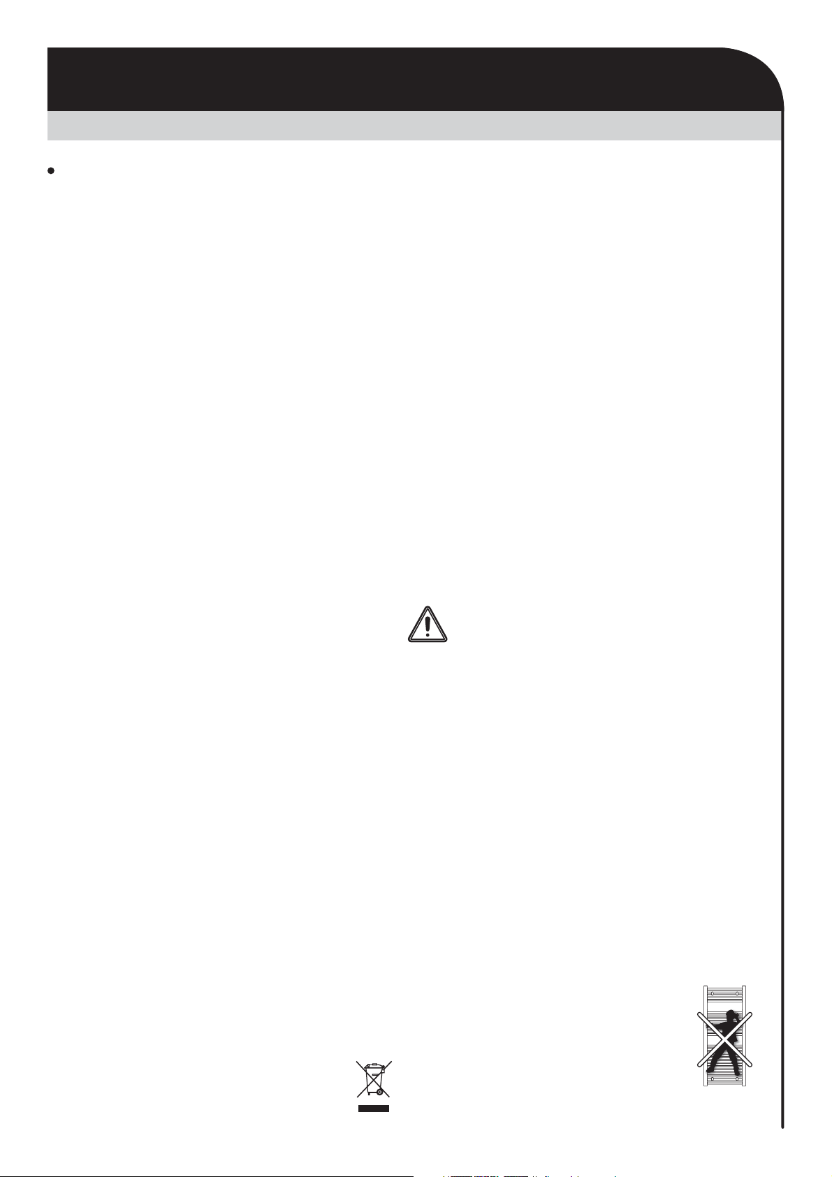
-Warning: In order to avoid a hazard for very
young children, this appliance should be ins-
talled so that the lowest heated rail is at least
600 mm above the floor.
- If the removal of the appliance is
necessary, do not remove or refit the
appliance onto the wall-mounting
brackets without making sure it
is cold and the main supply to the
system is off.
WARNINGS AND PRECAUTIONS
INSTALLING THE HEATING DEVICE
Warnings
All damage resulting from non-compliance
with this advice gives rise to non-application
of the terms of the manufacturer’s warranty.
-Do not use the appliance outdoors.
- Your appliance is intended for domestic usage
and must not be used for other purposes.
-IMPORTANT: It is strongly NOT recom-
mended to dry out synthetic clothes directly
on towel rails.
Unlike towels, this type of material (nylon, lycra,
polyester, acrylic…) often present in the cur-
rent clothes, are more sensitive to a direct heat
source.
If the synthetic material is fragile, this can lead
a color transfer on the heater body frequently
indelible and then permanent.
-If the appliance has fallen on the ground, has
been damaged or does not work properly, do
not switch it on and ensure that the power sup-
ply to it has been cut off (by means of a fuse or
of a circuit breaker).
-Never disassemble the appliance. A badly-re-
paired appliance may present risks for the user.
Please consult your local point of sales regar-
ding any problems.
-If the power supply cable is damaged, it must
be replaced by the manufacturer, its after-sales
service department or another electrical pro-
fessional in order to avoid any dangers arising.
-The heating appliance has been filled with a
precise quantity of thermal fluid (a product
safety data sheet is available upon request).
-Should a leak occur, switch off the appliance,
put it somewhere out of the way so that the fluid
spill does not spread and so that the thermal
fluid is not accidentally swallowed by a child,
and then immediately contact the company
that sold you the appliance or a representative
of the manufacturer.
Any tasks which require opening and closing
plugs and screws should only be carried out by
a properly accredited representative of the ma-
nufacturer.
-When the heating appliance is scrapped, com-
ply with legislation and regulations regarding
disposal of the thermal fluid. Refer to the
Waste Electrical and Electronic Equip-
ment Directive (WEEE Directive).
THA INT ENG AT V00 16 10 2018
44
Before connecting up the radiator to the
mains power supply, switch off mains power
at the main circuit breaker.
The product is a class II IP44 device, therefore
it can be installed in all the rooms of a house
including in safety zone 2 and Out of Zone in ba-
throoms. The heating device must be installed
in such a way that on-off switches and other
control devices cannot be touched by a person
located in a bath or in a shower cabinet (in ac-
cordance with the BS 7671:2018 Requirements
for Electrical Installations will be issued on 2nd
July 2018 and is intended to come into effect on
1st January 2019.
The electric towel rails must not be located im-
mediately below a socket-outlet.
The towel rails must be set up at least 15 cm
from any obstacle (ie shelving, curtains, items of
furniture, etc).
A means of disconnection mains supply capable
of disconnecting all poles, having a contact sep-
aration of at least 3mm in accordance with local
regulations and installation rules.
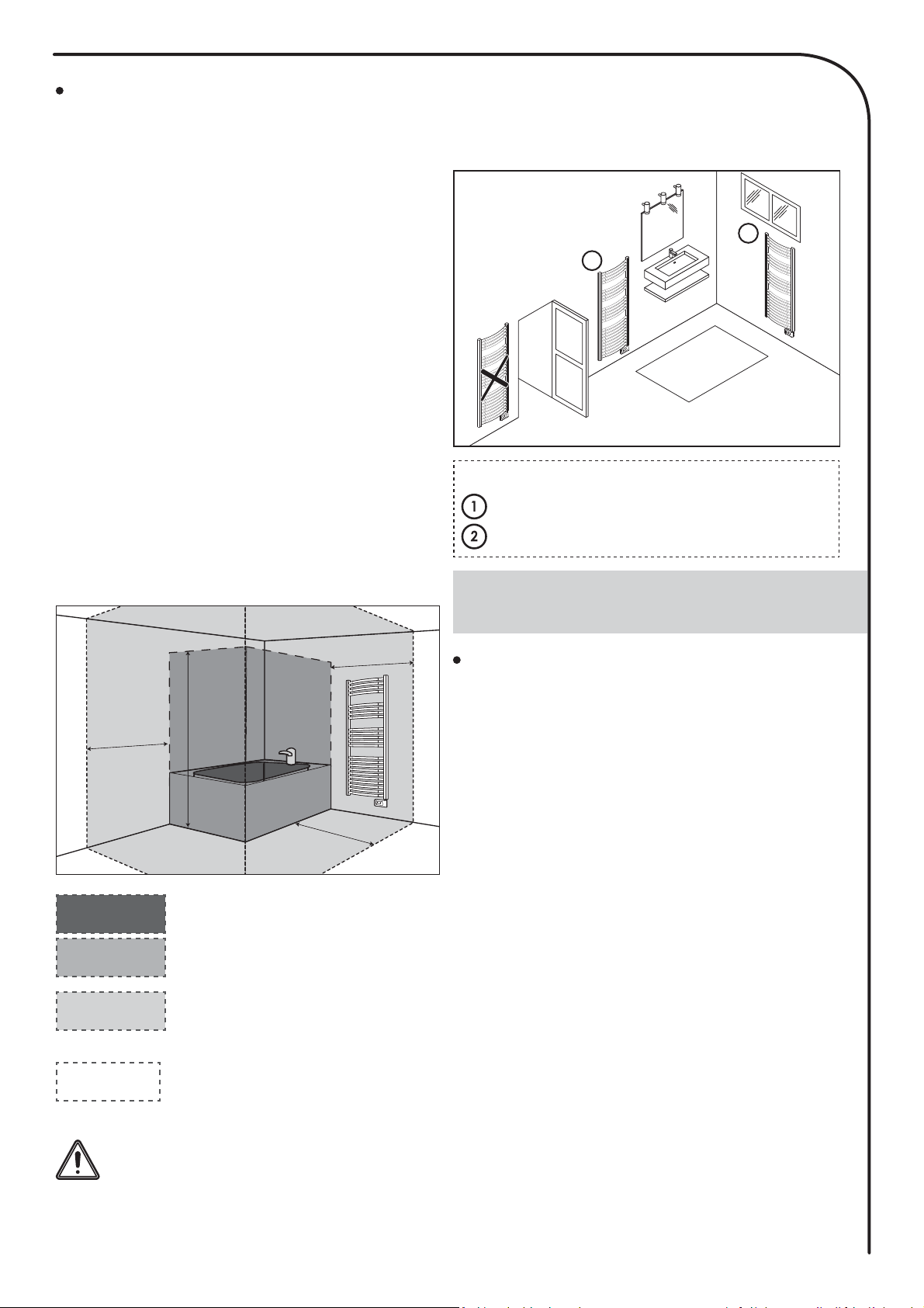
Suggestion, positioning, location
This picture is only for your reference.
In any case, the product must be ins-
talled by a qualified professional instal-
ler, according to applicable standards
and directives of the country in which
it is installed.
Locate the heater within minimum distances
from obstacles.
Installation recommended in the context of
using automatic opened window detection.
Connecting the device
CONNECTING, WALL-MOUNTING
PROCEDURE
Zone 2
Zone 2
Out of zone
Out of zone
Zone 1
Zone 1
0,60 m
0,60 m
0,60 m
2,25 m
Zone 0
No electric heating device
Zone 0
Zone 1
Electric heating device of class
II and IPX4 protected by a diffe-
rential circuit breaker 30mA.
Zone 2
Electric heating device of class
I or II protected by a differential
circuit breaker 30mA.
Out of zone
Legend
= the preferred location
= another location
2
1
All electrical installation work should be car-
ried out by a suitably qualified Electrician or
other competent person.
-
The power supply of the device must have a
mean of disconnection main supply capable of
disconnecting all poles, having a contact sepa-
rator of at least 3mm in accordance with local
regulations and installation rules, a protection
by a 30mA differential switch and a protection
device against overloads adapted to the cha-
racteristics of the connecting line.
-
Before you first use the equipment, check that
the voltage used 230-240V does indeed match
that listed on the device.
-
This electric towel rails is a class II device (mea-
ning that it has double electrical insulation).
Connection to earth is prohibited.
-
The three wires
must be connected in an elec-
trical connection fuse spur box which complies
with applicable standards.
ELECTRICAL CONNECTIONS
Monophase power supply 230V +/-10% 50Hz
You must insulate the pilot wire if it is not
used. Do not connect the pilot wire (black) to
the hearth.
5
- Blue-grey wire : Neutral
- Brown wire: Phase
- Black wire : Pilot wire (DO NOT CONNECT)
ONLY TO BE USED WITH AN EXTERNAL
CONTROLLER.
Important: Leave a gap of at least 150 mm
between the bottom part of the electric towel
rails (under the controller) and the floor.
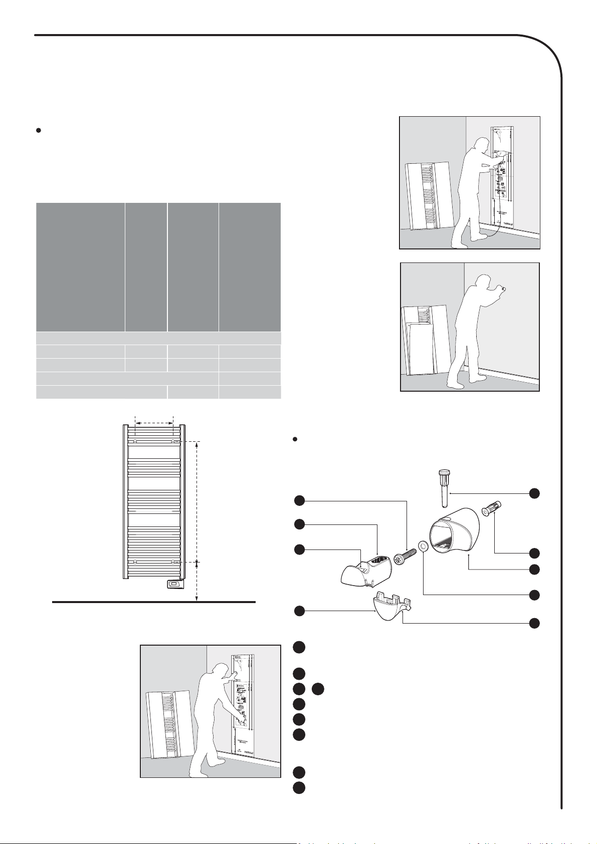
The positioning of the wall
mounting bracket and tracing
References
Power
out-
puts
(W)
B =
Dis-
tance
between
lower
and up-
per drill
holes
(mm)
C =
Horizontal
distance
between
drill holes
(mm)
White Version
B-ECO-0500 500 588 320
B-ECO-0700 700 966 320
Chrome Effect
B-ECO-0500CH 500 588 320
A = 400mm
B
C
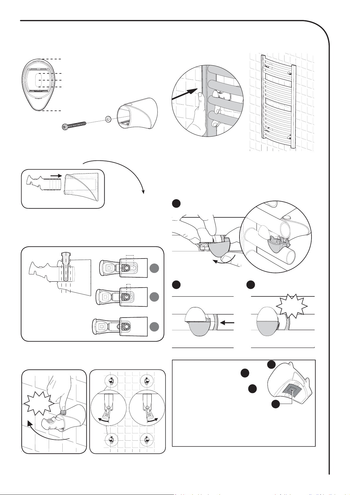
Use the drilling template supplied to attach
your towel rails to the wall.
Stage 1
Open the tem-
plate and position
it against the wall,
at the desired loca-
tion.
Ensure that the
bottom of the tem-
plate touches the
floor or the top of
the skirting board,
in order
that the fitting height can be adjusted.
Important: in the presence of very young
children, it is recommended that the template
be positioned at least 30 cm above the floor.
Stage 2
Find the power of
your electric towel
rails and drill the
corresponding
holes into the wall.
Stage 3
Remove the tem-
plate then screw
the wall-mounting
brackets of the
electric towel rails
into the wall.
Important:
use a screw an-
chor which is sui-
table in relation to
the wall type (screw Ø 6mm max).
Description of wall-mounting
brackets
Fixing screw of the wall-mounting bracket Ø
6mm max
1
Locking part
4
Pin
5
Screw anchor.
Important: adapt the type of
screw anchor to the nature of the partition
wall (Example: plasterboard)
6
Sleeve
7
Washer
8
Compensator damper pad
3 9
Support
2
1
2
4
7
8
5
6
9
3
6
1-Mounting of the 4 patented wall-mounting
brackets
Top
Bottom
Centre the screw
3-Setting up of the towel rails on the
wall-mounting brackets
1- Insertion
2- Setting of the
depth
2-Insertion and setting the depth of the sup
ports
A
B C
CLIC
4- Locking of supports
Insert the locking parts (1 per support) making
sure to position the notches in the 2 grooves lo-
cated below the head of the mobile support
.
Important :
Each locking part (
1
) is
equipped with a small pad
in translucent silicone (
2
).
This pad serves to counter-
balance the assembly and
the mounting tolerances. In
some cases, if inserting the locking part is
difficult, you may need to remove the small
silicone pad to facilitate insertion.
1
2
4- Locking 3- Setting of the angle
clic
ABC
12 mm
A
B
C
6 mm
7
Thank you for choosing one of our
products we are confident that you will
get many years of service.
Our range of electric towel rails with
thermal fluid and digital controls with
innovative style was designed and
developed to bring you the comfort
of heating without maintenance and
significant energy savings thanks to
smart features your Intelliheat towel
rails incorporates innovative technolo-
gies designed for your comfort and to
increase your energy savings, control
performance PID (stability), open win-
dow detection, 7 day and daily . In new
build or renovation applications, our
products will provide you with comfort
and satisfaction!
- A range of curved towel rails adapted to the dimension of your ba-
throom*:
2 finishings: white and chrome effect.
2 powers: 500W and 700W.
2 heights: 940 and 1318 mm.
1 width: 500 mm.
* Refer to table 20
- Simple and stylish: towel rails are equipped with 22mm diameter rails
which give them a robust and professional appearance while maintain-
ing a harmonious and uncluttered style.
- Innovation “chrome effect”: maintaining aesthetics and performance-
while optimising thermal comfort.
- Smart electronic controller: this means stable and accurate tempera-
tures in your bathroom all year round.
- Setting temperature can be viewed in all operating modes.
- Help for the visually impaired: the button power on/Heating
standby mode is in relief to be easily identifiable to the touch. The de-
vice has audible beeps indicating the change from the Heating standby
mode to active mode.
- Boost: Adjustable up 90 minutes, increases the speed at which your
bathroom heats up and also allows damp clothes and towels to dry
quickly.
New smart features
- Gauge consumption: An automatic indication of the level of energy
consumption according to the setting temperature.
- Power consumption indication: posting of the estimated amount of
energy consumed in kWh since the last reset to 0 of the energy meter.
- Opened window detection: Automatic switching to frost protection
mode when the device detects a significant drop in temperature.
- 7 day and daily : you have the option, for each day of the week, of
assigning five different program profiles (P1, P2, P3, non-stop Comfort,
non-stop Eco).
- Child anti-tamper: The control panel can be locked, making changes
impossible.
- Special safety for social or private rental housing:
- Limits of the adjustment range of the Comfort setting temperature.
- PIN code lock of settings reserved for professionals.
- Safety overheating:
- Immersion heater with dual safety:
- Safety level 1: an Integrated thermostat protects the towel rails
against any temporary overheating ;
- Safety level 2: Integrated thermal-fuse is triggered if the overheating
itself extended beyond the authorized temperature limit.
- Ambient temperature limit during the Boost: when Boost is active,
the towel rails must heat the room up to an ambient temperature
limit. When it is reached, the Boost automatically stops.
- Active memory: Permanent backup of the whole of settings and pro-
gramming, backup date and time of 3hrs typical.
- 4 transparent patented wall-mounting brackets:
- Innovative style, transparent and discreet.
- Quick to install: up to 3 times less than a standard screw installa
tion.
- Easy to install, towel rails is secured by wall-mounting brackets
before locking.
- Setting of the depth ideal for renovation.
- Mechanical strenght, high resistance to weight and heat.
- Optional infrared remote control (sold separately): supplied with a
wall base, you can remotely control Balneum Eco+.
- Optional hangers (sold separately): 2 ergonomics hangers fixed on
the towel rails for easy hanging towels or bathrobes.
OVERVIEW
BENEFITS
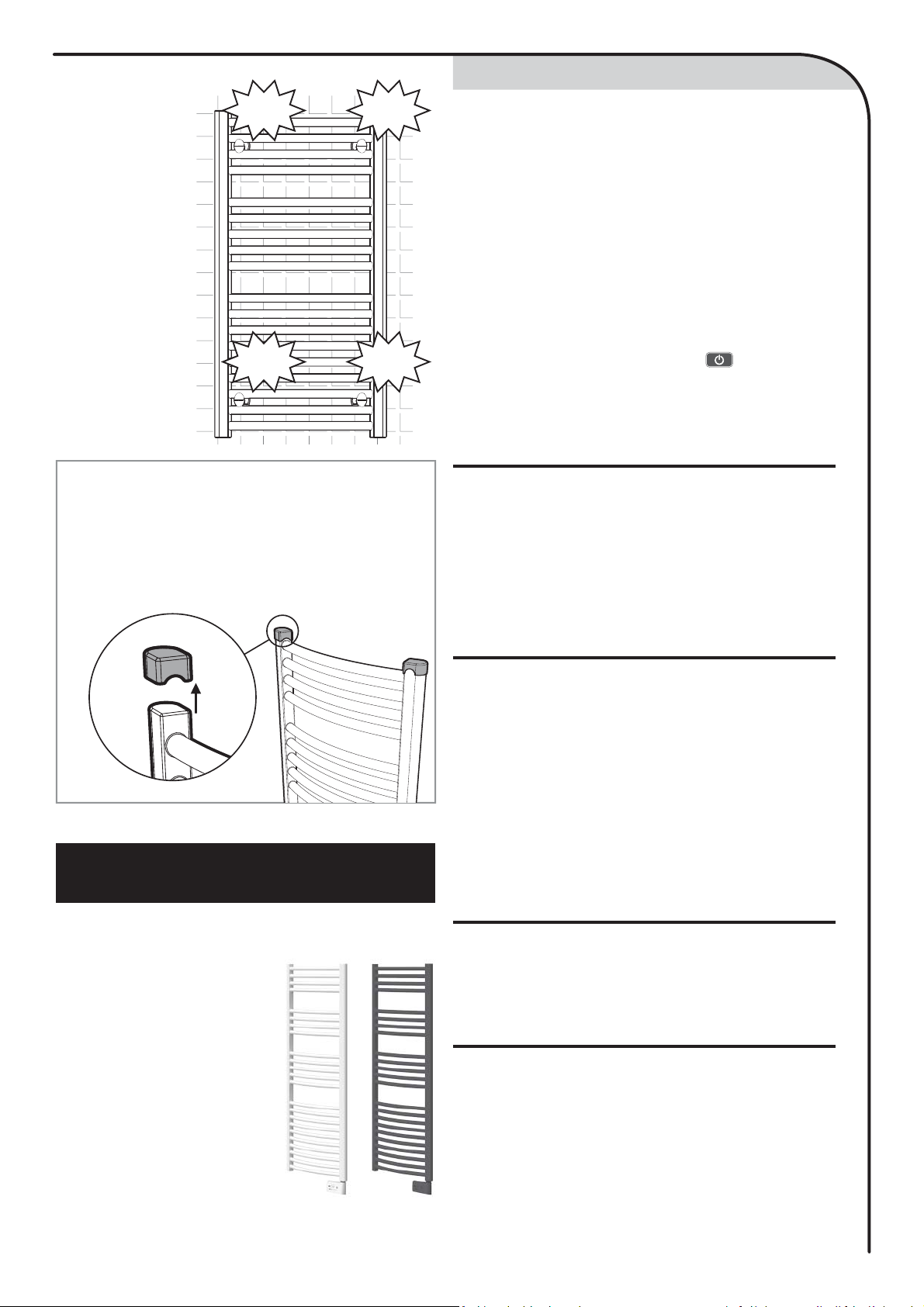
The towel rails
is now secured
and locked on
its supports.
CLIC
CLIC
CLIC
CLIC
Important:
Before heating on, it is imperative to remove
the protective caps located at the ends of
the towel rails.
Indeed, these are exclusively intended to
protect the angles of the device during
transport.

8
DIAGRAM
OPERATING
SELECTING THE OPERATING MODE
POWER ON/HEATING STANDBY
MODE
• Buttons overview
2
2
1 6
4 53
2
2
1
3
4 5
7
8
6
9
Gauge consumption
2
Boost indicator light
1
Heating indicator
3
Days of the week (1=Monday … 7= Sunday)
4
Setting temperature
5
Opened window detection indicator
6
Keypad locked
7
Radio transmission indicator
8
Operating modes:
Auto mode
Comfort mode
Eco mode
Frost protection mode
Time and date setting mode
Programming mode
Settings
9
• Indicators overview
Important: In Auto, Comfort, Eco and Heating standby modes, the back-
light turns off automatically after 20 seconds if no buttons are pressed. It
will be necessary to reactivate it by pressing one of the keypad buttons
before making settings.
Note
Before carrying out any setting procedures, ensure that
the keypad is indeed unlocked (see page 10).
Power on feature
Help for the visually impaired: sound signals
The device makes 2 short beeps to notify that it is in operating, in Auto
mode.
Press the button to put the device in operating, in Auto mode, both
Auto and Comfort modes are selected and the preset temperature ap-
pears on display.
3
beep
beep
Selecting operating modes
3
Button power on/heating standby mode
2
Infrared receiver
1
Save settings
5
Boost
6
Plus and minus buttons, used to set temperatures, time, date and
2
4
Help for the visually impaired: sound signals
The device makes 1 short beep to notify that it is in heating standby
mode.
Heating standby mode
This function allows you to stop the heating in summer, for example.
Press the button to put the device in heating standby mode.
beep
The
button allows you to adapt the operating
schedule of your device to your needs, depending on the
season, whether your home is occupied or not.
Press the
button several times to select the re-
quired mode.
Mode sequence
:
Auto Comfort Eco Frost Protection
Mode overview Display
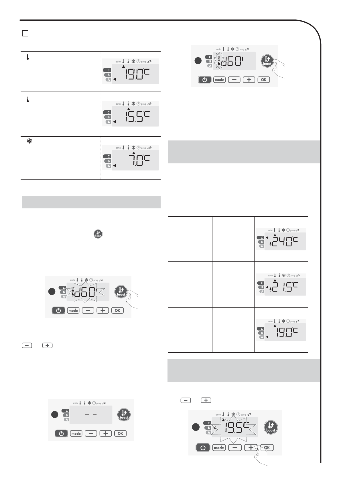
• Auto mode
In Automatic Mode, the device will
automatically change from Comfort mode
to Eco mode according to the established .
3
3 different cases depending on your set-up:
17 day and daily
Your device has been d and is executing Comfort and Eco mode orders in line
with the settings and time periods you have selected (see «7 day and daily
integrated» chapter page 10).
2Programming by pilot wire
If you do not want to use the programming feature, the device’s default setting
is non-stop Comfort for 7 days a week, you do not have to change any settings.
Orders sent by the pilot wire will only be applied in
Auto mode
,thus your
device will automatically receive and apply the d orders sent by your power
manager or your time switches (see Information about remote control by pilot
wire page 12)).
9
BOOST FEATURE
3Without
if the 7 day and daily is not enabled or no orders are being sent by pilot
wire, then your device’s factory settings mean that it will operate in nonstop
Comfort mode, 7 days of the week.
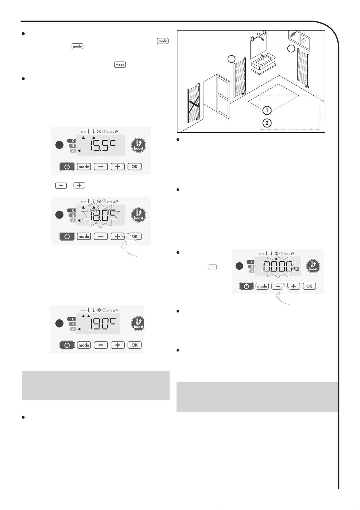
• Comfort temperature: 19°C
Non-stop Comfort mode. The device will
operate 24 hours a day to achieve the tem-
perature which has been set (e.g. 19°C).
The Comfort mode temperature level can
be set by the user (see Setting the comfort
mode temperature page 9).
• Eco temperature: 15,5°C
Eco, which means the Comfort Mode tem-
perature minus 3.5°C. This enables you to
lower the temperature without having to
reset the Comfort Mode temperature.
Select this mode for shortterm absences
(between 2 and 24h ) and during the night.
Restoring factory settings
see pages 15 et 17.
• Frost protection mode
This mode enables you to protect your
home against the effects of cold weather
(frozen pipes, etc.), by maintaining a mini-
mum temperature of 7°C
in it at all times. Select this mode when
you will be away from your home for a
long time (more than 5 days).
Important: the Boost mode can be enabled at any time, what-
ever the current operating mode (Auto, Comfort, Eco or Frost
protection).
To activate Boost mode, press , the desired temperature
setting
will be set at maximum for the time period you request. 60
minutes will flash by default.
- First press = Boost.
During the first minute: the boost symbol and the heating indicator
appear and the duration count flash.
During the first minute, you can modify the Boost duration from 0 to
the maximal authorised duration of the Boost, such as defined dur-
ing the user settings (see page 15 for more details) by intervals of 5
minutes (or more quickly by push superior to 2 seconds) by pressing
and . This modification will be saved and effective for the
next Boost.
After 1 minute, the Boost count begins and the time is running, min-
ute by minute.
Comment: After 1 minute, you can modify temporarily the duration:
it will be valid only for this active Boost and therefore non-recurring.
The Boost can stop for 2 different reasons:
- An order “Stop” has been sent by your energy manager through
the pilot wire:
The device stops, -- appears. The cursor moves above auto. When
the order Comfort will be sent, the device will be restarted until the
count end.
- Second press = Boost cancellation.
The cursor moves above the previous active mode and the setting
temperature appears.
The device switches off but the Boost mode is always active : the
count is always displayed, the Boost symbol and the heating indi-
cator flash on the display. When the temperature drops under the
maximal authorised temperature, the device will be restarted until
the count ends.
- If the ambient temperature reaches the maximal Boost
temperature during the count:
GAUGE CONSUMPTION,
ENERGY SAVINGS
SETTING THE COMFORT MODE
TEMPERATURE
The Energy Saving Trust (EST) and carbon trust recommends reduc-
ing temperature control down by 1°C to save up 10% of your energy
bill.
In the device display, a selector indicates the energy consumption level by
positioning it in front of the colour: red, orange or green. So, depending on
the setting temperature, you can choose your level of energy usage. As the
temperature setting increases, the consumption will be higher.
The gauge appears in Auto, Comfort, Eco and Frost protection modes and
whatever the temperature level.
C - Red colour
High Temperature
level: it is advisa-
ble to significantly
reduce the setting
temperature.
Setting tempera-
ture > 22°C
When the setting
temperature is higher
than 22°C
B - Orange colour
Average temperature
level: it is advisable
to slightly reduce the
setting temperature.
19°C < Setting tem-
perature d22°C
When the setting
temperature is higher
than 19°C and lower
or equal to 22°C
A - Green colour
Ideal temperature.
Setting tempera-
ture d19°C
When the setting
temperature is lower
or equal to 19°C
Using and you can adjust the temperature from 7°C to 30°C
by intervals of 0.5° C.
Note: you can limit the Comfort temperature, see page 14 for more
details.
You can access the Comfort temperature set up from the Auto and Com-
fort Mode. It is preset to 19°C.
10
CONSUMPTION INDICATION
ACCUMULATED IN KWH, ENERGY
SAVINGS
CHILD ANTI-TAMPER,
KEYPAD LOCK/UNLOCK
7 DAY AND DAILY PROGRAM
INTEGRATED, ENERGY SAVINGS
It is possible to see the estimation of energy consumption in kWh since the
last reset of the energy meter.
Display of the estimated power consumption
To see this estimation, from Auto, Com-
fort, Eco or Frost protection mode, then
press .
To exit the display mode of consump-
tion: press or , the device is
automatically in the previous active mode.
1234567
To reset the energy meter, from Auto, Comfort, Eco or Frost protection
mode, then proceed as follows.
Resetting the energy meter
1-
Press .
2-
Press simultaneously and for more than 5 seconds.
To exit resetting the energy meter, press or , the device
is automatically in the previous active mode.
Keypad lock
To lock the keypad, press the
and buttons and hold them down
for 5 seconds. The padlock symbol
appears on the display, the keypad is
locked. 3
Keypad unlock
To unlock the keypad, press the and buttons hold them
down for 5 seconds again. The padlock symbol disappears from
the display, keypad is unlocked.
When keypad is locked, only the key is active.
If the device is on Heating standby mode when the keypad is
locked, you have to unlock it for the next heating on to access
the setup.
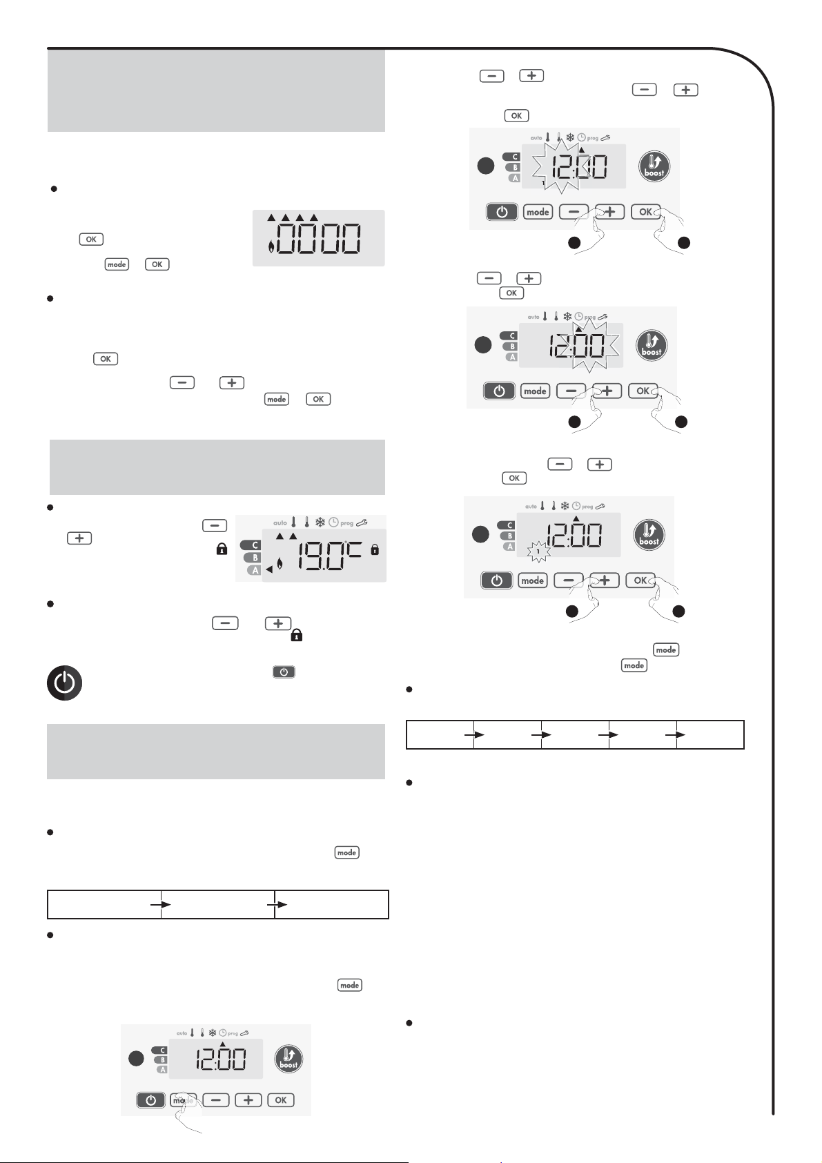
Access to the programming mode
From Auto, Comfort, Eco or Frost protection mode, press for 5
seconds to enter into the programming mode.
Schematic sequence of programming settings:
Setting time Setting day Programs
choice
In this mode, you have the option of programming your device, by
setting one of the five programs on offer for each day of the week.
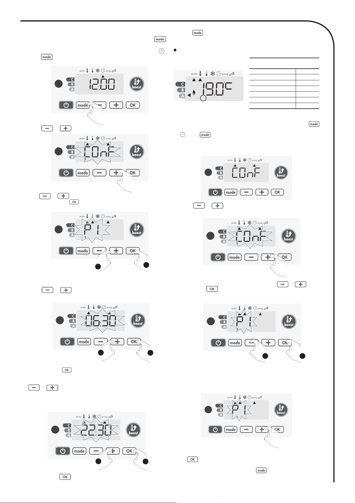
Setting day and time
In this mode, you can set day and time to program your device in line with
your needs.
1-From Auto, Comfort, Eco or Frost protection mode, press for 5
seconds.
The cursor moves to the setting day and time mode.
1
5 sec.
2-
Select using or . The two hour figures will flash.
The hours will scroll quickly, if you press the or and hold
them.
Save by pressing .
1
1
1
1
1
1
12
1
1 2
3- The two minute figures will flash.
Select using or .
Save by pressing .
1
1
1 2
4-
The cursor above the number 1 (which represents the Monday) will
flash. Select the date using or .
Save by pressing .
5- To change and/or allocate programs press . To exit the
setting the time and day mode, press 3 times.
Choices programs
Schematic sequence of programs:
Comfort Eco P1 P2 P3
Your device’s default setting is non-stop Comfort for 7 days a week.
Programs overview
- Comfort: your device will operate in Comfort mode, 24 hours a day,
as regards each day selected.
Note: You can set the Comfort mode temperature to the tempera-
ture you require (see Setting the comfort mode temperature page 9).
- Eco: The device will operate 24 hours a day in Eco mode.
Note:
You can set the temperature-lowering parameters (see Setting the
Eco mode temperature lowering-level page 14).
- P1:
your device will operate in Comfort mode from 06:00 to 22:00 (and in
Eco mode from 22:00 to 06:00).
- P2:
your device will operate in Comfort mode from 06:00 to 09:00 and
from 16:00 to 22:00 (and in Eco mode from 09:00 to 16:00 and from
22:00 to 06:00).
- P3:
your device will operate in Comfort mode from 06:00 to 08:00, from
12:00 to 14:00 and from 18:00 to 23:00 (and in Eco mode from 23:00 to
06:00, from 08:00 to 12:00 and from 14:00 to 18:00).
Potential modifications of programs
If the default time schedules for the P1, P2 and P3 programs do not suit
your routines, you can change them.
Modifying the P1, P2 or P3 programs. If you modify the time
schedules for the P1, P2 or P3 programs, the schedules will be
modified for all the days of the week for which P1, P2 or P3 had been
set.
11
1- If you just set the time and day, go to step 2.
From Auto, Comfort, Eco or Frost protection mode, press
for 5 seconds.
When the cursor moves above the set day and time mode ,
press shortly.
1
2-
Press or . The cursor moves above prog.
1
1
1
1
1
1
1
1
1
1
1
1
1
1
1
1
3-
With or , select P1.
P1 will flash. Press for 5 seconds to make changes.
1
1
1
1
1
1
1
1
1
5 sec.
2
1
Save by pressing .
4- The P1 start time (which by default is 06:00) will flash.
Using or , you can change this time, by increments of
30 minutes.
2
1
5-
The P1 end time (which by default is 22:00) will flash. Using
or , you can change this time, by increments of 30
minutes.
2
1
Save by pressing .
6-
Press to exit the programming Mode and return to Auto Mode.
Note: without action on the keys, it will return to Auto after a few minutes.
Choices and allocation programs
Correspondence days /
numbers
Monday
1
Tuesday
2
Wednesday
3
Thursday
4
Friday
5
Saturday
6
Sunday
7
Prior information:
display area
2
1-
If you just set the time and day, the cursor moves automatically under
PROG.
From Auto, Comfort, Eco or Frost protection mode, then press
for 5 seconds. When the cursor positionned under the set time symbol
, press again.
The days of the week will scroll on display with the programs that you set
for them, meaning Comfort «CONF» every day.
1
2-
Press or .
The program set for day 1 (1= Monday, 2 = Tuesday, etc.) will flash.
1
1
1
1
1
1
1
1
1
3- Chose the program you want for this day with or . Save
by pressing .
1
1
1
1
1
1
1
1
1
1
1
1
1
1
1
1
1
1
1 2
4-
The program assigned to the second day of the week (Tuesday) will
flash.
Repeat the procedure described previously (in point 3) for each day of
the week.
2
2
2
2
2
2
2
2
2
2
2
2
2
2
2
5- Once you have chosen a for each day, confirm your selection by press-
ing . The days of the week will successively scroll on display with
the that you set for them (P1, P2, P3, CONF or ECO).
To exit the Programming mode, press twice.
12
OPEN WINDOW DETECTION,
ENERGY SAVINGS INFORMATION ABOUT REMOTE
CONTROL BY PILOT WIRE
Viewing the programs that you have selected
- From Auto, Comfort, Eco or Frost protection mode, press
for 5 seconds. Press twice, the program for each day of the
week (Comfort, Eco, P1, P2 or P3) will scroll on display in front of
you.
- To exit the program viewing mode, press twice.
Manual and temporary exemption from a
running program
This function allows you to change the setting temperature temporar-
ily until the next scheduled change in temperature or the transition to
0:00.
Example:
1-
The device is in Auto mode, the running program is Eco 15,5°C.
3
2-
By pressing or , you can change temporarily the desired
temperature up to 18°C for example.
3
3
3
3
3
3
3
3
3
3
3
3
3
3
3
3
3
3
3
3
3
3
3
3
3
3
3
3
Note: The cursor corresponding to the operating mode, i.e Eco mode
in our example, is blinking during the duration of the temporary der-
ogation.
Important information about the open window
detection
Important: the open window detection is sensitive to temperature
variations. The device will react to the window openings in accord-
ance with different parameters: temperature setting, rise and fall of
temperature in the room, the outside temperature, the location of the
device...
If the device is located close to a front door, the detection may be
disturbed by the air caused by open door. If this is a problem, we
recommend that you disable the automatic mode open window de-
tection (see page 16). You can, however, use the manual activation
(see below).
2
1
Legend
= the favourite location
= another location
Overview
Lowering temperature cycle by setting frost protection during ventilation
of a room by opened window. You can access the open window detection
from the Comfort, Eco and Auto modes. Two ways to enable the detector:
- Automatic activation, the lowering temperature cycle starts as soon as
the device detects a temperature change.
- Manual activation, the cycle of lowering temperature starts by pressing
a button.
Automatic activation (factory settings)
To disable this mode, see page 15.
The device detects a temperature fall. An opened window, a door to
the outside, can cause this temperature fall.
Note: The difference between the air from the inside and the outside
must cause a significant temperature fall to be perceptible by the de
-
vice.
This temperature drop detection triggers the change to Frost Protec
-
tion mode.
Manual
activation
By pressing for
more than 5 seconds,
the device will switch on
Frost protection mode.
5 sec.
Frost protection digital meter
When the device performs a lower temperature cycle due to opened win-
dow, a meter appears on the display to show the cycle time.The counter is
automatically reset at the next time to Frost protection by opened window
(automatic or manual activation).
Stop the Frost protection mode
By pressing one button, you stop the Frost protection mode.
Note: if a temperature rise is detected, the device may return to the pre-
vious mode (active mode before the open window detection)
.
• Overview
Your device can be controlled by a central control unit through a pilot wire,
in which case the different operating modes will be remotely enabled by
the r. You can only control the device by pilot wire in the Auto mode. In the
other modes, the orders transmitted by the pilot wire will not be executed.
In general, a pilot wire control system makes it possible to impose exter-
nally a lowering of the temperature setpoint, combined with the internal
programming.
If several lowering requests appear simultaneously, priority is given to the
lowest temperature setpoint, thus maximizing savings (see information on
priorities for different modes on page 13).
3-
This change will be automatically cancelled at the next change of
or transition to 0:00.
3
13
INFORMATION ABOUT PRIORITIES
BETWEEN THE DIFFERENT MODES
OPTIONAL: REMOTELY MANAGEMENT BY
INFRARED REMOTE CONTROL
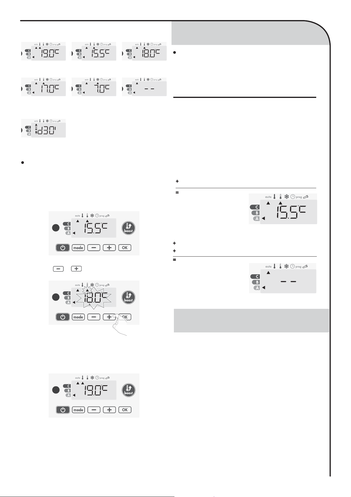
Below the different views of the display for each order sent by pilot
wire:
Pilot wire = Comfort Pilot wire = Eco
Comfort - 3,5°C
Pilot wire = Eco - 1
Comfort - 1°C
3 33
Pilot wire = Eco - 2
Comfort - 2°C
Pilot wire =
Frost
protection
Pilot wire = Stop
(Heating standby
mode)
33
Pilot wire = Boost
Exemption to an order coming from a pilot wire
external r
This feature allows you to modify temporarily the setting temperature un-
til the next order sent by the central control unit or the transition to 00:00.
Example:
1-
The device is in Auto mode. The central control unit sent an Eco order
15,5°C.
3
3-
This modification will be automatically cancelled at the next order sent
by the central control unit or the transition to 00:00.
3
2-
By pressing or , you can change temporarily the desired
temperature up to 18°C for example.
3
3
33
3
3
3
3
3
3
3
3
3
3
3
3
3
3
3
3
3
3
3
3
3
33
3
3
Note:
The cursor corresponding to the operating mode, i.e Eco mode in
our example, is blinking during the duration of the temporary derogation.
In Comfort, Eco and Frost protection modes, only orders of the open
window sensor will be considered.
In Auto mode, the device can receive different orders coming from :
- 7 day and daily programming integrated (Comfort or Eco orders);
- 6-order pilot wire, if connected to a central control unit;
- Open window detector.
Principe
In general, it is the lowest received order which prevails except
when the pilot wire is connected to an energy management sys-
tem, in this case the orders of the pilot wire take priority.
- If an open window is detecting, switching to frost protection
takes precedence unless a load shedding order is present on
the pilot wire.
- The Boost activation will take precedence over others orders
received except when the standby (stop) order is present on
the pilot wire, the device will switch off and the Boost will be
not activated.
• Examples
7 day and daily programming = Comfort
Pilot wire 6 orders = Eco
Eco
3
7 day and daily programming = Eco
Pilot wire 6 orders = Stop (heating standby mode)
Open window detector = Frost protection
Heating standby mode
Your towel rails can be managed by a remote control with infrared
transmission through its IR receiver located on the front of the con-
troller.
For installing and operating the remote control, refer to its instruction
manual.

14
BACKLIGHT SETTING
SETTING THE ECO MODE
TEMPERATURE LOWERING-LEVEL SETTING THE COMFORT MODE
TEMPERATURE
ACCESS
USER SETTINGS
SETTING THE FROST PROTECTION
TEMPERATURE
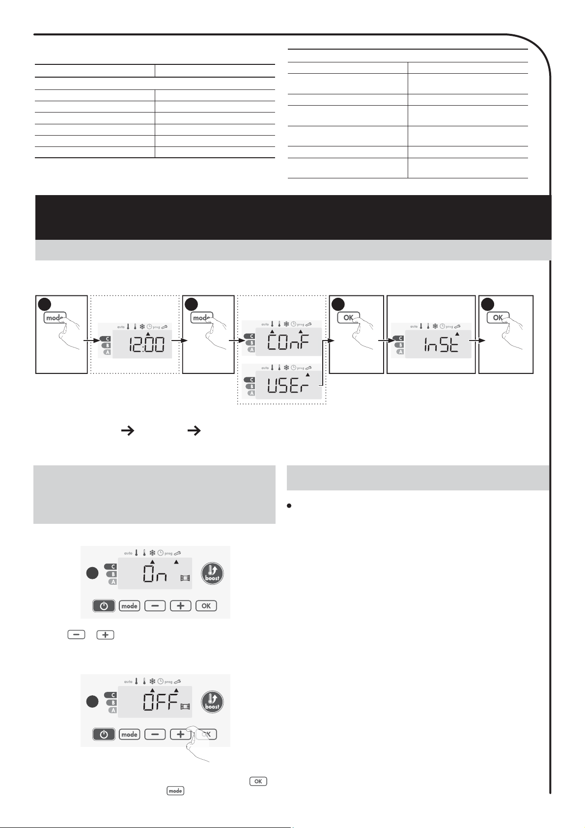
You access to user settings in 3 steps:
From Auto, Comfort, Eco or Frost protection mode :
Information
display
1
Information
display
1
8VHU
= User settings
Press for 5
seconds
1
Press briefly
twice
2
Press briefly
3
Setting sequence:
Backlighting Eco mode temperature lowering-level Frost protection temperature Comfort setting temperature limit Maximal
Boost duration Maximum ambient temperature
1-
Three modes can be set:
/= Temporary backlighting: Backlight of the display when a
button is pressed.
/
=
Non-stop backlighting: Backlight of the display all the time.
/ = In this version, the device will work according to the L1 mode.
L3 mode is the default setting.
Press or to choose the setting you require.
2- Press to save and move to the next setting.
To exit the user settings, press twice.
The drop in temperature is set at -3.5°C compared to the set tem-
perature of the Comfort mode. You can adjust the lowered level from
-1°C to -8°C, by intervals of 0.5°C.
Important: whatever the lowering level set, the Eco setting tem-
perature will never exceed 19°C.
3-
Press or
to obtain the temperature level you require.
To exit the user settings, press twice.
4- Press to save and move to the next setting.
Your device is preset at 7°C. You can adjust the Frost protection tem-
perature from 5°C to 15°C, by intevals of 0.5°C.
6- Press to save and move to the next setting.
To exit the user settings, press twice.
5-
Press or to obtain the temperature you require.
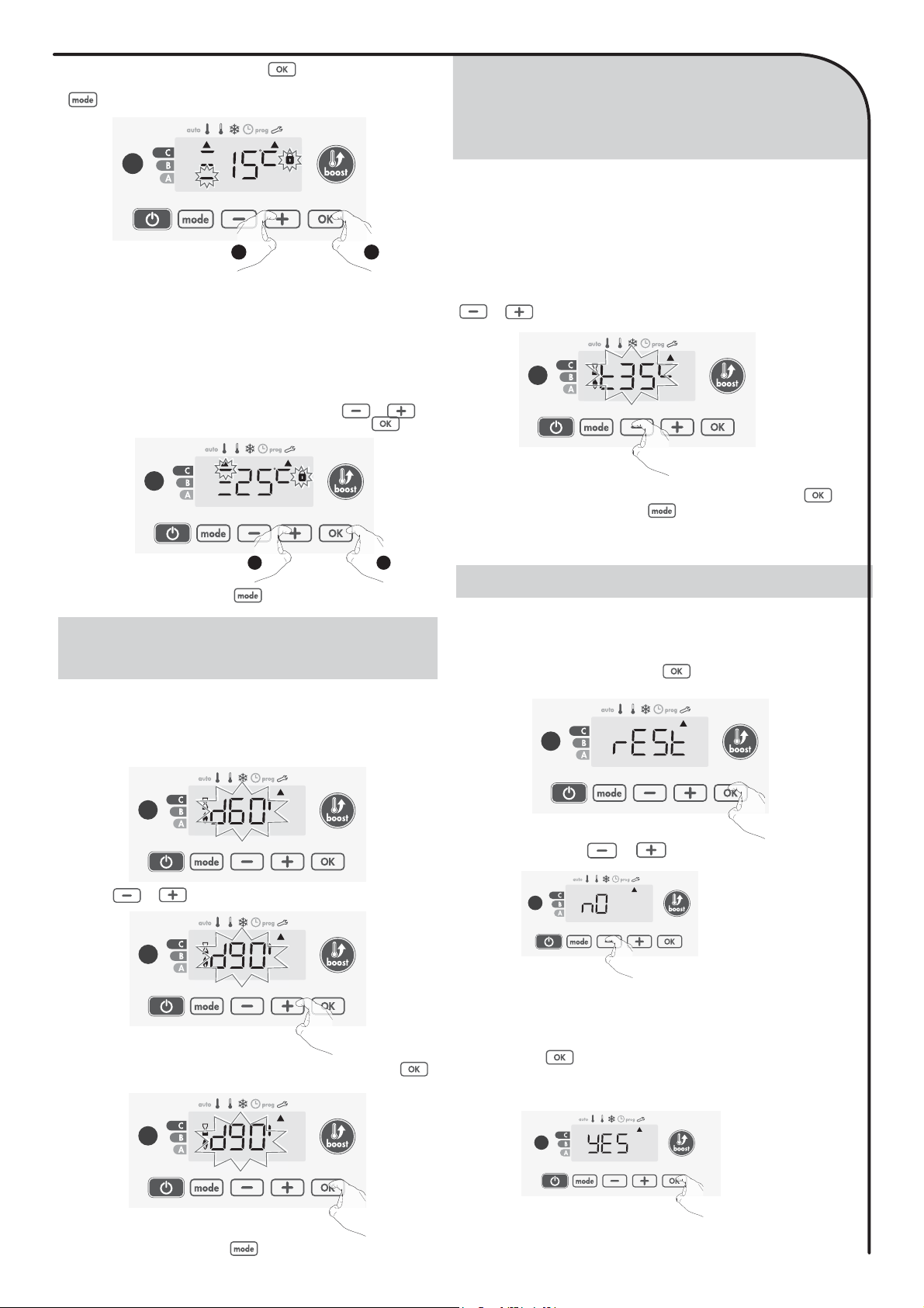
You can limit the setting temperature range by introducing a maxi-
mum and / or minimum setting, preventing unintentional changes in
temperature.
• Low-temperature limitation
Locking of the setting range using a minimum temperature stop, pre-
venting the temperature from being set below that temperature.
The minimum setting is preset to 7°C. You can adjust from 7°C to
15°C by intervals of 1°C.
7-To change the minimum temperature setting, press or then
save by pressing .
15
SETTING OF THE MAXIMUM
DURATION OF AUTHORISED BOOST
SETTING OF THE MAXIMUM
AMBIENT TEMPERATURE FOR THE
AUTOMATIC STOP OF THE BOOST
RESTORING FACTORY SETTINGS
21
If you do not want to change it, press : the device changes auto-
matically to set the maximum setting. To exit the user settings, press
twice.
• High-temperature limitation
Locking of the setting range using a maximum temperature increase, pre-
venting the temperature from being set above that
temperature.
The maximum setting is preset to 30°C. You can adjust from 19°C
to 30°C by intervals of 1°C.
8-
T
o change the maximum temperature setting, press or .
To save and move automatically to the next setting, press .
To exit the user settings, press twice.
21
The maximum duration of Boost is preset at 60 minutes. You can
adjust it from 30 to 90 minutes by intervals of 30 minutes.
9-
The Boost symbol and the heating indicator appears on the display
and the preset duration of 60 minutes flash.
10- Press or to display the desired duration.
11-
To save and move automatically to the next setting, press .
To exit the user settings, press twice
.
When the Boost is enabled, the device has to heat the room until the
temperature limit: the maximum ambient temperature.
When it is reached, the Boost stops automatically.
It is preset at 35°C, you can adjust it from 25°C to 39°C by intervals
of 1°C.
The Boost symbol and the heating indicator appear on the display
and the maximum temperature flashes.
12-You can set the Boost maximum temperature by pressing
or from 25°C to 39°C by intervals of 1°C.
13-
To save and move automatically to the next setting, press .
To exit the user settings, press twice.
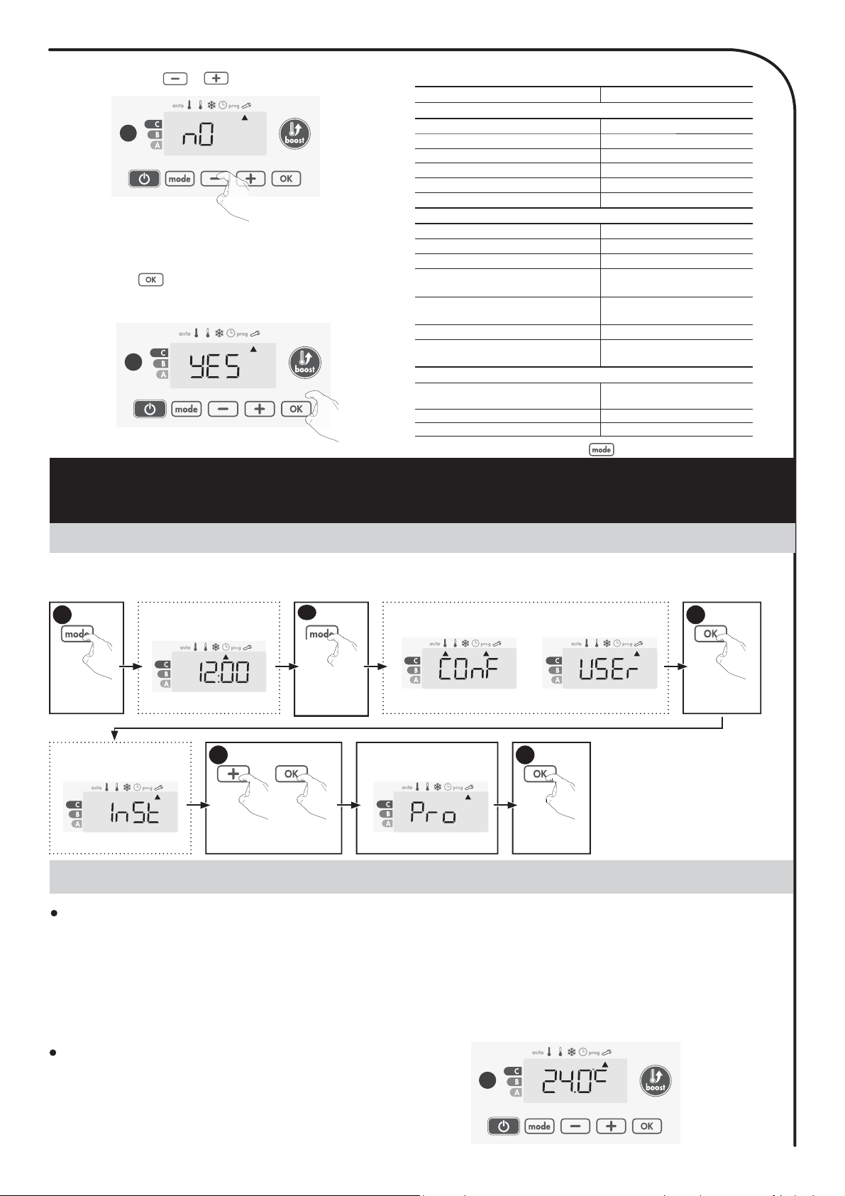
In order to a coming back to factory settings, proceed in the following
order:
1-
From the previous setting , press .5(67appears on the
display.
2- 12
appears. Press or to select
<(6.
\HV=
Factory settings reset
12=
Factory settings not reset
3-Press the key for 5 seconds. The device returns to its initial
configuration and goes back automatically to the home display of
the user settings.
5 sec.
16
dŚĞĨŽůůŽǁŝŶŐĨĂĐƚŽƌLJǀĂůƵĞƐǁŝůůďĞĞīĞĐƟǀĞ
ACCESS
INSTALLER SETTINGS
You access to installer settings in 4 steps:
From Auto, Comfort, Eco or Frost protection mode :
Information
display
1
Information
displays
1
Press for 5
seconds
1
Press briefly
twice
2
Press for 10
seconds
3
Press briefly
4
InSt
с/ŶƐƚĂůůĞƌƐĞƫŶŐƐ
Setting sequence:
Open window detection PiN code lock Restoring factory settings
OPEN WINDOW DETECTION,
ACTIVATION/DEACTIVATION OF THE
AUTO MODE
1-
Press or .
21 = automatic mode enabled. .
2)) = automatic mode disabled.
The automatic mode enabled is the default setting.
2- To save and move automatically to the next setting, press .
To exit the installer settings, press 3 times.
Overview
Your heating device is protected by a safety code against
nonauthorised use. The PIN code (Personal Identity Number) is a
customisable 4 numbers code. When enabled, it prevents access to
the following settings:
- Selecting the Comfort mode : The access to the Comfort mode
is forbidden, only the Auto, Eco and Frost protection modes are
available.
- Minimum and maximum limits of the set temperature range (the
Comfort temperature modification is forbidden out of the authorised
setting range).
- Programming mode.
- Open window detection settings.
- Setting the Eco mode temperature lowering-level.
- Setting the Frost protection temperature.
3 important steps are needed for the first use of the PIN code lock:
1 - PIN code initialisation,
enter the preset PIN code (0000) to access
to the feature.
2 -
Activation of the PIN Code to lock settings which will be protected
by the PIN code.
3 - Customizing the PIN code, replace 0000 by the customized code
PIN CODE LOCK
Parameters &ĂĐƚŽƌLJƐĞƫŶŐƐ
KƉĞƌĂƟŶŐ
ŽŵĨŽƌƚƐĞƫŶŐƚĞŵƉĞƌĂƚƵƌĞ 19°C
ƵƌƌĞŶƚŽƉĞƌĂƟŶŐŵŽĚĞ Auto
ƵƌƌĞŶƚƉƌŽŐƌĂŵ Comfort
ŶĞƌŐLJĐŽŶƐƵŵƉƟŽŶŝŶĚŝĐĂƚŽƌ 0 kWh
ŽŽƐƚĚƵƌĂƟŽŶ 60 min.
<ĞLJƉĂĚůŽĐŬ Disabled
hƐĞƌƐĞƫŶŐƐ
ĂĐŬůŝŐŚƟŶŐ L3
ĐŽŵŽĚĞƚĞŵƉĞƌĂƚƵƌĞůŽǁĞƌŝŶŐͲ
level -3,5°C
&ƌŽƐƚƉƌŽƚĞĐƟŽŶƚĞŵƉĞƌĂƚƵƌĞ 7°C
DŝŶŝŵƵŵƐĞƚŽĨŽŵĨŽƌƚƐĞƫŶŐ
ƚĞŵƉĞƌĂƚƵƌĞ 7°C
DĂdžŝŵƵŵƐĞƚŽĨŽŵĨŽƌƚƐĞƫŶŐ
ƚĞŵƉĞƌĂƚƵƌĞ 30°C
DĂdžŝŵĂůŽŽƐƚĚƵƌĂƟŽŶ 60 min.
DĂdžŝŵƵŵĂŵďŝĞŶƚƚĞŵƉĞƌĂƚƵƌĞ
ĨŽƌƚŚĞĂƵƚŽŵĂƟĐƐƚŽƉŽĨƚŚĞŽŽƐƚ 35°C

17
PIN code initialisation
By default, the PIN code is not enabled. 2))appears on the display.
1-
By default registered PIN code is 0000.
Press or to select 0. It is blinking. Save by pressing
.
1 2
2-
For others numbers, select 0 by press .
When 0000 appears, press on again to save.
The PIN code is initialized, the next setting automatically appears:
PIN Code activation.
Activation/deactivation of the PIN Code
1- 2)) appears on the display.
Press or to enable PIN code.
21 appears on the display.
21 = PIN code enabled
2)) = PIN code disabled
The PIN code is enabled. Any modification of reserved settings listed
in “Overview” is now impossible.
2-
Press to save and return to the home installer settings display.
Customizing the PIN code
If you have just activated the PIN code, follow the stages described
below.
Alternatively, you must copy the steps 1 and 2 of the initialisation
process as well as the steps 1 and 2 of the activation process before
personalising the PIN code.
Please remember that the personalisation of the PIN code can only
be set once the initialisation and activation of the PIN code have been
completed.
1- When 2Q appears, press for at least 5 seconds.
5 sec.
2-
The 0000 code appears and the first number blinks. Press or
to select the first desired number then press to save.
Repeat this operating for remaining 3 numbers.
1 2
3-
Press to confirm. The new code is now saved.
4- Press again on to exit setting PIN code mode and go back to
the home display of the installer settings.
To exit the Installer settings, press twice.
If the PIN code protection is disabled, the user and installer settings
are re-initialized:
1- From the PIN code setting, press . UHVWappears briefly
on the display.
RESTORING FACTORY SETTINGS
18
AMBIENT TEMPERATURE SENSOR ADJUSTMENT
ACCESS
EXPERT SETTINGS
You access to expert settings in 5 steps.
From Auto, Comfort, Eco or Frost protection mode :
IŶĨŽƌŵĂƟŽŶ
display
1
/ŶĨŽƌŵĂƟŽŶ
displays
1
Press for 5
seconds
1
Press briefly
twice
2
Long and simultaneous 10
seconds press
4
Press for 10
seconds
3
Press briefly
5
Information
display
3UR
= Expert settings
Overview
Important: This operating is reserved for professional installers only;
any wrong changes would result in control anomalies.
In which case if the temperature measured (measured by a reliable ther-
mometer) is different by at least 1°C or 2°C compared to the setting tem-
perature of the radiator.
The calibration adjusts the temperature measured by the ambient tem-
perature sensor to compensate for a deviation from + 5°C to - 5°C by
intervals of 0.1°C.
Important: Before carrying out the calibration it is recommended to
wait for 4h after the setting temperature modification to insure that
the ambient temperature is stabilized.
Ambient temperature sensor adjustment
1- If the room temperature difference is negative, example :
Setting temperature (what you want) = 20°C.
Ambient temperature (what you read on a reliable thermometer) = 18°C.
Difference measured = -2°C.
To correct, then proceed as follows :
Sensor temperature = 24°C
(The measured temperature may be different due to the location of
the thermostat in the room).
To exit the installer settings, press twice.
Settings Factory settings
Operating
Comfort setting temperature 19°C
Current operating mode Auto
Current program Comfort
Energy consumption indicator 0 kWh
Boost duration 60 min.
Keypad lock Disabled
User settings
Backlighting L3
Eco mode temperature lowering-level -3,5°C
Frost protection temperature 7°C
Minimum set of Comfort setting
temperature 7°C
Maximum set of Comfort setting
temperature 30°C
Maximal Boost duration 60 min.
Maximum ambient temperature for the
automatic stop of the Boost 35°C
Installer settings
Automatic open window
detection Enabled
PIN code protection Disabled
Value of the PIN code 0000
The following factory values will be effective:
\HV= Factory settings reset
12= Factory settings not reset
3-
Press the key for 5 seconds. The device returns to its initial
configuration and goes back automatically to the home display of
the installer settings.
5 sec.
2-12 appears. Press or to select <(6.

19
OTHER REMOTELY MANAGEMENT BY
POWER SHUTDOWN
IN CASE OF POWER CUT, BACKUP
POWER
POWER CUT
Decrease the temperature measured by the ambient temperature sensor
by 2°C by pressing .
In our example the measured temperature by the sensor goes from 24°C
to 22°C.
2- If the room temperature difference is positive, example :
Setting temperature (what you want) = 19°C.
Ambient temperature (what you read on a reliable thermometer) =
21°C.
Difference measured = +2 °C.
To correct, then proceed as follows :
Sensor temperature= 21°C.
(The measured temperature may be different due to the location of
the thermostat in the room).
Increase the temperature measured by the ambient temperature sensor
by 2°C by pressing .
In our example the measured temperature by the sensor goes from 21°C
to 23°C.
2-
To save and move automatically to the next setting press . To
exit the Expert settings, press 3 times.
The reset to zero of the sensor calibration
To put the value of the correction to “0”, do the following :
1- When the temperature measured by the sensor appears, press
or for at least 3 seconds.
3 sec.
Press to confirm.
A number appears. This is a special setting dedicated to the production
and already set in factory, please do not modify. To exit the Expert set-
tings, press 3 times.
Information displays appear each time when a mode is pressed. They are
also settings adjusted in the factory, please do not modify. Any wrong
changes would result in control anomalies.
Important : The power supply of the device should be
cut when working on the electrical system only. The
load shedding does not be operated by an additional
system with mechanized power shutdown (with contac-
tor…). Unlike pilot wire shedding, the load shedding
with frequent mechanized power shutdowns can cause
deterioration of the device depending of the quality of
switching elements used. This type of deterioration
would not be covered by the manufacturer’s warranty. If
remotely stop or standby orders should be frequently
operated, you must use the pilot wire.
- After short power cuts (less than 3 hrs), the device will start up
again without any outside input being required – you do not have
to do anything. All the settings and the correct time will be saved.
When the main power supply returns, your device will again op-
erate using correct time and the settings that were d before the
power cut (as regards desired temperature, operating mode, , etc.).
It will start up again in the mode which was active before the power
outage
- For longer power supply cuts (more than 3 hrs), check the timer
setting. All the other settings are automatically and permanently
saved.
DIAGNOSIS SUPPORT
TROUBLESHOOTING
• Heating body
Temperature differences on the heating device:
- The surfaces of the different parts of the heating device may pres-
ent, in normal operating, temperature differences more or less no-
ticeable to the touch according to the methods of use.
This has no effect on the safety and performance requirements
applicable for the product.
For example, the last rail located on the top of the towel rails is
often cooler than the others, indeed, when the thermal fluid rises in
temperature, it expands in the heating body, which requires us not
to fill it completely.
The device doesn’t heat:
- Check the position of the circuit breaker/power supply protection
fuse in your main distribution/fuse board.
- Check the active operating mode (see page 8), you could be in
“Heating standby mode” or in Auto mode, with an imposed stop
order by the energy manager (see page 12).
- Check the ambient temperature using a thermometer: if it is el-
evated, the device has reached the desired temperature setting,
therefore it is normal that it doesn’t heat more.
- Switch the power off for 5 seconds at the mains supply then switch
back on again.
The room temperature is not high enough, the device is not pro-
viding enough heat:
- Check the active operating mode (see page 8), you may be in Eco,
Frost protection, Standby or in Auto mode, with an imposed lower-
ing by the integrated programming or the energy manager. Switch
to the permanent Comfort mode.
- Check the active temperature setting and increase it if necessary
(see page 9).
- If the problem persists, check the towel rails sizing compared with
the bathroom height and insulation.
20
MAINTENANCE
TECHNICAL
INFORMATION
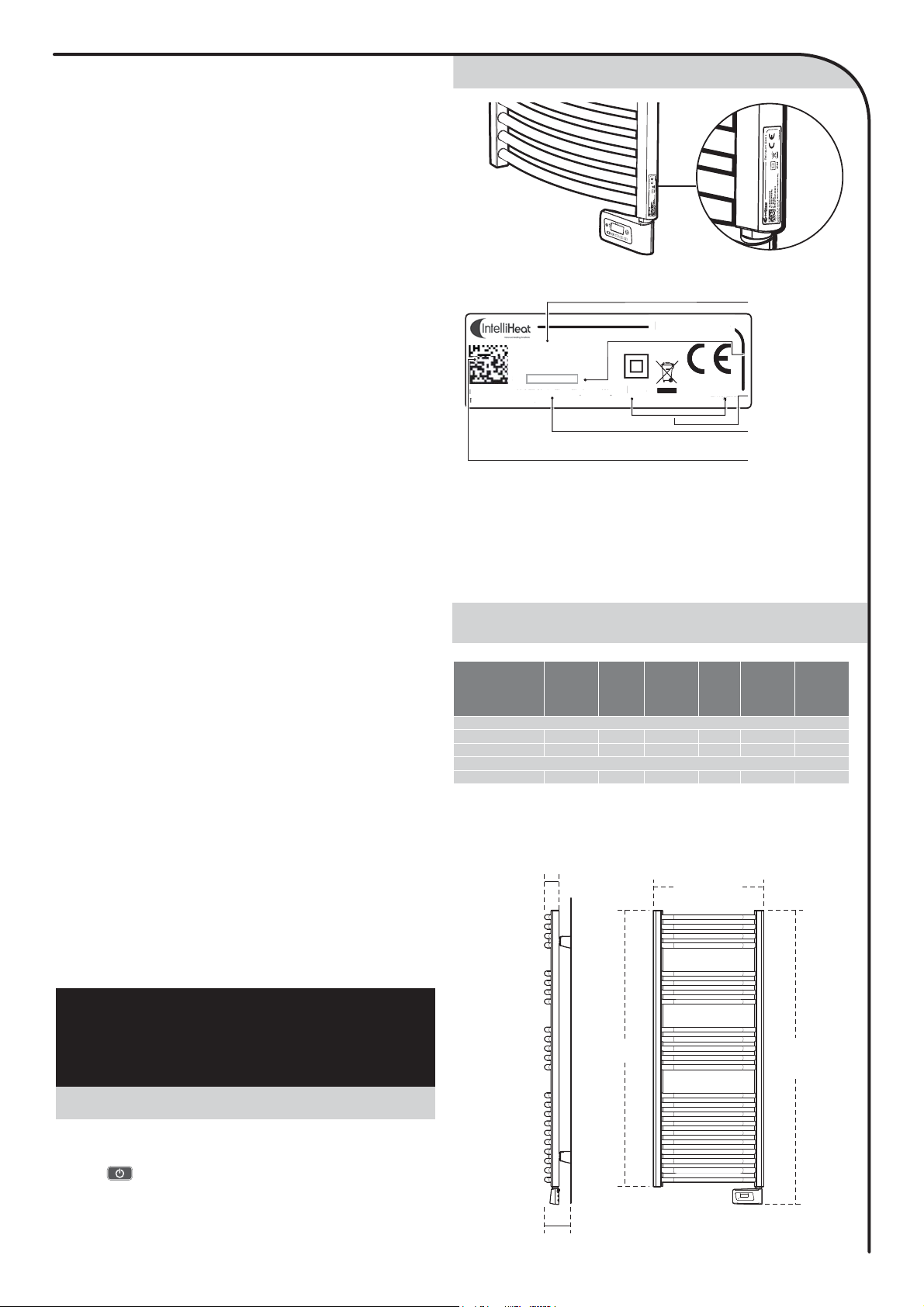
PRODUCT LABEL
INFORMATION REQUIREMENTS FO
R
Before any maintenance work, enable the heating standby mode by
pressing button, switch off the fuse spur or plug and wait until
the device is cold.
The device can be cleaned with a damp cloth ; never use abrasives
or solvents.
The device heats continuously and is hot on the surface:
- In operating, it is normal that the device surface is hot, the surface
temperature is limited.
- Check that the controller, located at the bottom of the towel rails, is
not influenced by an airstream.
- Check that the set temperature has not been changed.
- If the problem persists, check the towel rails sizing compared with
the bathroom height and insulation.
Several situations can generate a slight metallic slam:
- The device is fixed on an irregular unlevelled wall.
- The device is fixed on an uninsulated wall.
- The device is in a stream of cold air.
- The device is badly positioned in the wall-mounting brackets.
- Heat up or sudden temperature change.
• Controller
The ambient temperature is lower than the setting temperature:
- Check the programming mode. You may be in a d Eco
period.
- Check the time setting.
- Otherwise, switch the power off for 5 seconds at the mains supply
then switch back on again.
The ambient temperature measured by a thermometer doesn’t
correspond to the setting temperature after several hours.
- An offset is always possible, you can refine the device setting (see page
17).
The device does not heat while the heating indicator is on:
- The heating symbol is lit on the display, the unit is cold, contact your
installer.
The device automatically enters in Eco or Frost protection mode
closed windows:
- If the device is connected to a central programming via pilot wire, check
the programming of the central.
- Disable the automatic opened window detection mode (see page 16)
.
(U appears on display:
- Switch the power off for 5 seconds at the mains supply.
-- appears on display, the device is in heating standby mode:
- Check that your energy manager or r is in heating standby mode.
The device is in Auto mode, remotely controlled by an energy manag-
er or r, but the programming orders are not executed by the device:
- Make sure the energy manager or the r is in good condition, refers to the
user instructions.
- Change the batteries of the energy manager or the r if this one contains
it.
No symbol appears on the display screen.
- Check the position of the circuit breaker / power supply protection fuse
in your main distribution/fuse board.
You want to increase or decrease the setting temperature but press-
ing a key on the keyboard has no effect:
- If the padlock symbol is displayed, the keypad lock is enabled.
Unlock the keypad as shown in the manual, child anti-tamper section
(see page 10).
- Check the changes, restrictions temperature settings (see page
15).
You made a mistake while setting the advanced settings:
- Just restore factory settings – see the “Restoring factory settings” par-
agraph (see pages 15 and 17). This will erase any programs that you
would have implemented.
If the problem persists, then contact your installer.
References
Power
outputs
(W)
Height
(mm)
Com-
plete
height
(mm)
Width
(mm)
Depth
of the
product*
(mm)
Number
of towels
spaces
White version
B-ECO-0500 500 860 940 500 65 2
B-ECO-0700 700 1238 1318 500 65 3
Chrome effect version
B-ECO-0500CH 500 860 940 500 65 2
* For the depth of
Balneum Eco+
Ecosens² installed, add about 53 to 66 mm
to the value of its depth
IP44
S/N 27330100001
P: 500W
U: 230V~/50Hz
B-ECO-0500
THAINT05E
Intelli Heat © Ltd - Unit 18, Napier Place, Stephenson Way,
Thetford, Norfolk, IP24 3RL
Balneum Eco+
Serial
number
Product
reference
Certification
logos and
symbols relating
to standards
B
a
l
neum
E
co
+
Manufacturer
identification
Product
identification
IP4
4
S/N 2733010000
1
P
: 500W
U
: 230V~/50H
z
I
I
n
ntel
li Heat
©
Ltd
-
Unit 18, Napier Place, Stephenson Way,
T
T
T
T
Thetf
ord, Nor
f
olk, IP24 3RL
,
p
y,
T
05
5E
E
E
E
E
THAINT
INT
INT
INT
INT
INT
INT
N
IN
IN
INT
INT
INT
INT
INT
NT
INT
NT
N
N
N
N
Important: The serial number allows the manufacturer to identify
your device. If you contact your installer about the product you have
purchased, take yourselves previously the references of your device.
Make sure to keep instructions even after the product installation.
DIMENSIONNAL SPECIFICATIONS
Complete
height
Width
height
depth
(installed)
depth
This manual suits for next models
3
Table of contents
Popular Bathroom Fixture manuals by other brands


sanswiss
sanswiss 19259 installation instructions

Geberit
Geberit IDO Glow 600 Operating and maintenance instruction

Hans Grohe
Hans Grohe Showerpipe Puro Instructions for use/assembly instructions

Hans Grohe
Hans Grohe Croma Classic 100 28539 Series Assembly

Noro
Noro FROST CONCEPT manual

noken
noken SOTTO 100237665-N350798853 manual


