manuals.online logo
Brands
  1. Home
  2. •
  3. Brands
  4. •
  5. Intellitec
  6. •
  7. Switch
  8. •
  9. Intellitec Monoplex User manual

Intellitec Monoplex User manual

1
SERVICE MANUAL
MONOPLEX
SPEAKER SWITCH
CONTROLLER
1 KEY
2 TV GRND
3 TV SOUND
1 L SPKR -
2LRAD-
3 L SPKR +
4 L RAD +
5 R SPKR +
6 R SPKR -
7 KEY
8 R RAD +
9RRAD-
1PNLLTS
2 TV PWR
3 KEY
4 SPKR SW
5 AMP PWR
6 GROUND
pin1
J2
pin1
J1
pin1
J3
NOTE: The MONOPLEX SPEAKER SWITCH is a centralized audio switching center.
Power from both the ignition and battery is fed into the module. The power of
the battery is available at this box. Inadvertent shorts at this box could result in
damage and/or injury. All servicing of this box should be done only by a qualified
Service Technician.
Tools required: Low current Test Light, Accurate Voltmeter (digital read-out preferred)
Intellitec Part No. 00-00348-000
www.intellitec.com
1485 Jacobs Rd.
Deland, FL 32724
386.738.7307
INTELLITEC
Monoplex Speaker Switch
53-00348-100 REV. B 032519
2
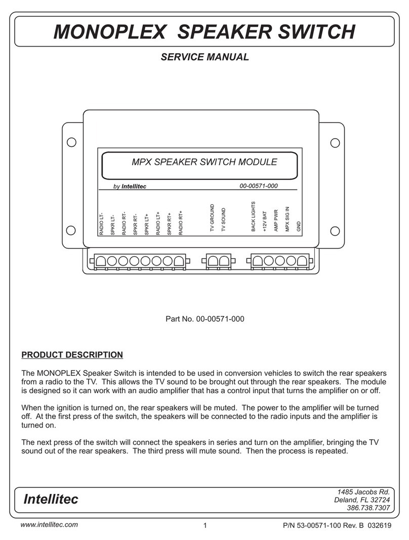
PRODUCT DESCRIPTION
The MONOPLEX Speaker Switch is intended to be used in conversion vehicles to switch the rear speak-
ers from a radio to the TV. This allows the TV sound to be brought out through the rear speakers. The
module is designed to work with an audio amplifier that has a control input that turns the amplifier on or
off.
When the ignition is turned on, the radio will always be connected to the amplifier and the amplifier will
be turned on. Whether the television is on or off will affect the operation. If the TV is off, the first press
of the switch will turn the amplifier off, muting the sound to the rear speakers. At the next press of the
switch, the amplifier is turned on again.
If the television is turned on, the first press of the switch mutes the sound by turning the amplifier off.
The next press of the switch will turn the amplifier on and switch the input of the amplifier to the TV,
bringing the TV sound out of the rear speakers, amplified. The third press will return radio to the rear
speakers. If the sound from the TV is coming from the rear speakers and the TV power is turned off, the
module will automatically switch the input back to the radio input.
HOW IT WORKS
The MONOPLEX Speaker Switch provides a semi-automatic means of switching the four inputs of a
stereo audio amplifier to allow switching between the four radio inputs and two TV inputs. The actual
switching is done with four double pole, double throw relays. These relays are controlled by logic elec-
tronics to provide the functions of the unit. When the unit is not powered, the four radio inputs and the
respective four amplifier outputs are connected. When the power is first applied, the amplifier power
signal is on, or 12 volts. At the first press of the remote switch (This is momentary short to ground.), the
amplifier power signal will go off, but the relays will not switch . At the next press the amplifier power
signal will go on again. (This output is current limited to approximately 80 milliamps.
If the TV has power applied to it and power is available at J1 - 2, at the first press of the remote switch,
the power signal to the amplifier will go off, but the relays will not switch. At the next press of the remote
switch, the amplifier power signal will come back on and the relays will switch, causing the TV sound to
come from the speakers. At the third press of the switch, the relays switch back and the amplifier signal
stays on, bringing the radio sound out of the speakers again. If the TV sound is selected and the TV
power is turned off, the module will automatically switch back to radio sound.
www.intellitec.com
1485 Jacobs Rd.
Deland, FL 32724
386.738.7307
INTELLITEC
Monoplex Speaker Switch
53-00348-100 REV. B 032519
3
PLUGS - PINS & FUNCTIONS
Problem
No radio sound from rear speakers.
TV sound won’t come from speakers.
Won’t switch functions.
One channel not working.
TROUBLE SHOOTING
Possible
Cause/Solution
Check for +12 volts coming to J1 - 1. If missing,
check fuse F10 on Master.
Check for power at amplifier. If missing, check
fuse supplying amplifier.
Check for radio fader settings. Set to middle of
range.
Check power signal at J1- 5. Should be +12 volts.
If not, check for shorted wire.
Check for +12 volts on J1 - 2. If missing, check
wiring.
TV sound not coming into J3. Check for sound
signal at J3.
Check voltage on Speaker Switch, J1 - 4. Should
be +12 volts, no button pressed, 0 volts with a
button pressed.
Unplug J2. Check for continuity between corre-
sponding inputs and outputs. If open, replace
module.
J2 - 9 pin
Pin Function
1 Left Speaker -
2 Left Radio -
3 Left Speaker +
4 Left Radio +
5 Right Speaker +
6 Right Speaker -
7Key
8 Right Radio +
9 Right Radio -
J1 - 6 pin
Pin Function
1 Power Input
2 TV Power Input
3Key
4 Speaker Switch
5 Amplifier Power
6 Ground
J3 - 3 pin
Pin Function
1Key
2 TV Ground
3 TV Sound
www.intellitec.com
1485 Jacobs Rd.
Deland, FL 32724
386.738.7307
INTELLITEC
Monoplex Speaker Switch
53-00348-100 REV. B 032519
4
www.intellitec.com
1485 Jacobs Rd.
Deland, FL 32724
386.738.7307
INTELLITEC
Monoplex Speaker Switch
53-00348-100 REV. B 032519

Other Intellitec Switch manuals

Intellitec 00-00571-000 User manual

Intellitec

Intellitec 00-00571-000 User manual

Intellitec MONOPLEX User manual

Intellitec

Intellitec MONOPLEX User manual

Intellitec 00-00571-000 User manual

Intellitec

Intellitec 00-00571-000 User manual

Popular Switch manuals by other brands

West Mountain Radio RIGrunner 4010S+ manual

West Mountain Radio

West Mountain Radio RIGrunner 4010S+ manual

Renkforce 1647064 operating instructions

Renkforce

Renkforce 1647064 operating instructions

GeMNeXT PS-4IN-UHD user manual

GeMNeXT

GeMNeXT PS-4IN-UHD user manual

Heltun QUINTO HE-RS01 user manual

Heltun

Heltun QUINTO HE-RS01 user manual

Terra SRM524 manual

Terra

Terra SRM524 manual

Raritan MasterConsole CAT Quick setup guide

Raritan

Raritan MasterConsole CAT Quick setup guide

GESTRA LRS 1-50 Original Installation & Operating Manual

GESTRA

GESTRA LRS 1-50 Original Installation & Operating Manual

Alcatel-Lucent OmniSwitch AOS Release 7 Guide

Alcatel-Lucent

Alcatel-Lucent OmniSwitch AOS Release 7 Guide

KTI KGS-1620 installation guide

KTI

KTI KGS-1620 installation guide

Avaya WLAN Security Switch 2300 Series Troubleshooting and Debug Guide

Avaya

Avaya WLAN Security Switch 2300 Series Troubleshooting and Debug Guide

TP-Link KS220M user guide

TP-Link

TP-Link KS220M user guide

Samsung SmartThings Hub quick start guide

Samsung

Samsung SmartThings Hub quick start guide

AVCOMM 608FX2 Quick installation guide

AVCOMM

AVCOMM 608FX2 Quick installation guide

NETGEAR FS116P - ProSafe 16 Port 10/100 Desktop... installation guide

NETGEAR

NETGEAR FS116P - ProSafe 16 Port 10/100 Desktop... installation guide

Grizzly G8290 instruction sheet

Grizzly

Grizzly G8290 instruction sheet

D-Link KVM-440 Quick install guide

D-Link

D-Link KVM-440 Quick install guide

B+B SmartWorx ESWGP206-2SFP-T user manual

B+B SmartWorx

B+B SmartWorx ESWGP206-2SFP-T user manual

CYP CLUX-4S2 Operation manual

CYP

CYP CLUX-4S2 Operation manual

manuals.online logo
manuals.online logoBrands
  • About & Mission
  • Contact us
  • Privacy Policy
  • Terms and Conditions

Copyright 2025 Manuals.Online. All Rights Reserved.