Inter-m PX-1650 User manual

PX-1650 Stereo Built In X-OVER
PX-1650_E 2003.9.8 10:42 AM 페이지2

Contents
Contents
1. Introduction/Unpacking and Installation .................................................................................1
2. Features ................................................................................................................................2
3. Precautions............................................................................................................................3
4. Front Panel Controls...............................................................................................................4
5. Top Panel Controls.................................................................................................................9
6. Rear Panel Controls .............................................................................................................12
7. Speaker Connections............................................................................................................14
8. Operating Tips.....................................................................................................................17
9. Applications ........................................................................................................................26
10. Block Diagram...................................................................................................................27
11. Specifications.....................................................................................................................28
OFFICE :
226-9 DUGJUNG - LI, HOE CHUN - EUB,
YANGJU - KUN, KYUNGKI - DO, KOREA
TEL : 82-351-860-7041~5, FAX : 82-351-858-1907
Home Page : http://www.inter-m.co.kr, http://www.inter-m.com
E-mail : [email protected]
PX-1650_E 2003.9.8 10:42 AM 페이지3

PX-1650 1
STEREO BUILT IN X-OVER
Introduction
Unpacking and Installation
Introduction
Thank you for purchasing a PX-1650 Stereo Quad Powered Mixer Built in X-OVER. The PX-1650 Series
provides an excellent balance of operability, functionally and ease of use. In order to take full advantage of
the PX-1650 Series capabilities and enjoy years of trouble-free use, please read this manual carefully.
Unpacking and Installation
Although it is neither complicated to install nor difficult to operate your set, a few minutes of your time is
required to read this manual for a properly wired installation and becoming familiar with its many features
and how to use them. Please take a great care in unpacking your set and do not discard the carton and
other packing materials. They may be needed when moving your set and are required if it ever becomes
necessary to return your set for service.
Never place the unit near radiators, in front of heating vents, to direct sun light, in excessive humid or dusty
location to avoid early damage and for your years of quality entertainment. Connect your complementary
components as illustrated in the following page.
RISK OF ELECTRIC SHOCK
DO NOT OPEN
CAUTION
CAUTION: TO REDUCE THE RISK OF ELECTRIC SHOCK.
DO NOT REMOVE COVER (OR BACK).
NO USER-SERVICEABLE PARTS INSIDE.
REFER SERVICING TO QUALIFIED SERVICE PERSONNEL.
WARNING
To prevent fire or shock hazard, do not
expose the unit to rain or moisture.
This symbol is intended to alert the user to the
presence of uninsulated “dangerous voltage”
within the product’s enclosure that may be of suf-
ficient magnitude to constitute a risk of electric
shock to persons.
This symbol is intended to alert the user to the
presence of important operation and mainte-
nance (servicing) instructions in the literature
accompanying the appliance.
Caution: To prevent electric shock do not use this (polarized) plug
with an extension cord, receptacle or other outlet unless
the blades can be fully inserted to prevent blade expo-
sure.
Attentions: Pour prévenir les chocs électriques ne pas utiliser cette
fiche polarisée avec un prolongateur, une prise de
courant on une autre sortie de courant, sauf si les
lames peuvent étre insérées à fond sans en laisser
aucune partie à découvert.
PX-1650_E 2003.9.8 10:42 AM 페이지4

PX-1650
2
STEREO BUILT IN X-OVER
Features
Features
- PX-1650 MONO INPUTS CHANNELS
The PX-1650 stereo quad powered mixer built in x-over provides 8, 12 channels of mono input that can be
mixed down to a stereo, 2 monitor, 2 EFFECT SEND output.
- XLR type connectors are provided for MIC jacks and 1/4” TRS connectors are provided for the LINE jacks.
- 2 STEREO CHANNELS
These mixing consoles provide 2 channels of stereo channel input that can be mixed down to a Stereo, 2
Monitor, 2 EFFECT sends out (MONITOR 1, 2 Per/EFFECT Send 1, 2 Post).
- 2 STEREO AUX RETURN
- 3 BAND EQ WITH SWEEPABLE MID-RANGE BAND
All mono input channels include 3 band EQ with sweepable mid-range frequency.
- INPUT CH INSERT I/O JACK
INPUT CH INSERT I/O jack is provided on each channel, allowing you to connect effect devices indepen-
dently for each channel.
- 7 BAND STEREO GRAPHIC EQUALIZER
Frequency Band: 63, 160, 400, 1k, 2.5k, 6.4k, 15kHz.
- 16 x 16 PROGRAMMABLE DSP
- 4 CHANNEL STEREO POWER AMP
250W×4, 4Ωat THD 0.1%.
PX-1650_E 2003.9.8 10:42 AM 페이지5

3
PX-1650
Precautions
Precautions
- AVOID EXCESSIVE HEAT, HUMIDITY, DUST AND VIBRATION
Keep the unit away from locations where it is likely to be exposed to high temperatures or humidity-such as
near radiators, stoves, etc. Also avoid locations which are subject to excessive dust accumulation or vibra-
tion which could cause mechanical damage.
- VENTILATION
The unit has ventilation slots on the side and bottom panels. Do not block these vents.
- AVOID PHYSICAL SHOCKS
Strong physical shocks to the unit can cause damage. Handle it with care.
- DO NOT OPEN THE CASE OR ATTEMPT REPAIRS OR MODIFICATIONS YOURSELF
This product contains no user-serviceable parts. Refer all maintenance to qualified Inter-M service person-
nel. Opening the case and/or tampering with internal circuitry voids the warranty.
- ALWAYS POWER OFF BEFORE MAKING CONNECTIONS
Always turn the power OFF before connecting or disconnecting cables. This is important to prevent damage
to the unit itself as well as other connected equipment.
- HANDLE CABLES CAREFULLY
Always plug and unplug cables-including the AC power cord-by gripping the connector, not the cord.
- CLEAN WITH A SOFT DRY CLOTH
Never use solvents such as benzine or thinner to clean the unit. Wipe clean with a soft, dry cloth.
STEREO BUILT IN X-OVER
PX-1650_E 2003.9.8 10:42 AM 페이지6

4PX-1650
STEREO BUILT IN X-OVER
Front Panel Controls
1. MONO INPUT SECTION
1. PEAK LED INDICATORS
This LED indicators let you check the level of the signal
input to the channel.
The peak indicator lights when the input signal reaches
3dB below the channel’s clipping point.
This indicator show the level of the post-EQ/pre-fader
signal. If the PEAK indicator lights more than briefly on
high-level transients, you should use the GAIN control to
decrease the input sensitivity of the channel. If this dose
not work, reduce the output level of the connected source.
2. GAIN CONTROL
This control adjusts the channel’s mic input sensitivity
between -60dB and -16dB and the line input sensitivity
between -30dB and +14dB. Continuously variable gain
control allows optimum adjustment to virtually any micro-
phone or line source.
3. EQUALIZER CONTROLS
This set of four controls allows you to individually modify
the channel’s response. Each channel of the PX-1650 is
equipped with a 3 band equalizer (EQ) that has shelving
HIGH and LOW controls, and a peaking MID control
with a sweepable center frequency (which is adjusted by
the MID FREQ control). Refer to “Using the Channel
Equalizers” on page 14 for details on the use of these
controls.
HIGH: 12kHz, ±15dB shelving type
MID: 250Hz~5kHz, ±15dB peaking type
LOW: 80Hz, ±15dB shelving type
1
0
20
25
30
35
40
10
15
5
PAN
LR
PEAK
EFX
010
EFX 1
010
EFX 2/REV
LOW
15 15
5250 FREQ
MID
15 15
HIGH
15 15
TRIM 60
30
14
16
010
MON
010
1
2
3
4
5
6
7
8
MON 1
MON 2
+20
+15
+10
+5
0
-5
-10
-15
-2020 50 100 200 500 1k 2k 5k 10k 20k
FREQUENCY (Hz)
RESPONSE (dB)
250 MID FREQ 5k
PX-1650_E 2003.9.8 10:42 AM 페이지7

5
PX-1650
4. MONITOR 1 AND 2 CONTROL
These control determines the level of the post-EQ/pre-fader signal that is sent from the channel to the
monitor mixing buses. All signal sent to the Monitor bus are mixed, then fed to the Monitor 1 and 2
Jacks on the top panel after their final output levels have been set by the Monitor 1 and 2 controls in the
Master control section.
5. EFFECT 1 CONTROL
This control determines the level of the post-EQ/post-fader signal that is sent from the channel to the
Effect 1 mixing bus. The channel signals mixed by this bus have their overall level set by the EFFECT
SEND 1 Control. Then are sent to the EFFECT SEND 1 jack. The output from this jack can be
processed by an external effect device.
6. EFFECT 2 CONTROL
This control determines the level of the post-EQ/post-fader signal that is sent from the channel to the
Effect 2 mixing bus. The channel signals mixed by this bus are sent via the EFFECT SEND 2 Control to
the EFFECT SEND 2 jack on the top panel. The output signal is also fed into the PX-1650 internal
digital signal processor. Thus, a signal fed to the Effect 2 bus using this control can be processed
externally or internally.
7. PAN CONTROL
This control pans the channel signal across the master L and R buses, thus determining the perceived
position of the sound from that channel in the output stereo sound field. If a PAN control is set all the
way to the left, for example, the sound from that channel will be heard from the left speaker system only.
If it is set all the way to the right, the sound will be heard from the right speaker system only.
Intermediate settings will cause the sound to appear at corresponding locations in the stereo sound field.
8. CHANNEL FADER
This is the channel’s main level control. It determines the level of the signal that is sent from the channel
to the master mixing and effect buses. It is the settings of the input channel faders that determine the
“mix”, or the balance of sound levels between the instruments or other sources connected to the inputs.
When a channel is not being used, its fader should be set at the minimum position to prevent the
addition of unwanted noise to the main program signal.
STEREO BUILT IN X-OVER
PX-1650_E 2003.9.8 10:42 AM 페이지8

6PX-1650
2. STEREO INPUT SECTION
1. PEAK LED INDICATORS
This LED indicators let you check the level of the signal
input to the channel.
The peak indicator lights when the input signal reaches
3dB below the channel’s clipping point.
This indicator show the level of the post-EQ/pre-fader
signal. If the PEAK indicator lights more than briefly on
high-level transients, you should use the GAIN control to
decrease the input sensitivity of the channel. If this dose
not work, reduce the output level of the connected source.
2. GAIN CONTROL
This control adjusts the stereo channel’s input sensitivity
between -20dB and +14dB. Continuously variable gain
control allows optimum adjustment to virtually any line
source.
3. EQUALIZER CONTROLS
This set of three controls allows you to individually
modify the stereo input response. Stereo channel of the
PX-1650 is equipped with the 3 band equalizer (EQ) that
has shelving HIGH, LOW, and Peaking MID controls.
Frequency response will be flat when the knob is center
position.
Will be flat when the knob is center position.
HIGH: 12kHz, ±15dB shelving type
MID: 2.5kHz, ±15dB peaking type
LOW: 80Hz, ±15dB shelving type
4~8. Please refer to Mono Input Section No. 4~8.
STEREO BUILT IN X-OVER
13/14
0
20
25
30
35
40
10
15
5
010
MON 2
PEAK
TRIM 20
LOW
15 15
MID
15 15
HIG
15 15
010
EFX 2/REV
01
EFX 1
EFX
BALANC
LR
MON
010
MON 1
14
1
2
3
4
5
6
7
8
+20
+15
+10
+5
0
-5
-10
-15
-2020 50 100 200 500 1k 2k 5k 10k 20k
FREQUENCY (Hz)
RESPONSE (dB)
PX-1650_E 2003.9.8 10:42 AM 페이지9

7
PX-1650
3. MASTER SECTION
1. OUTPUT LEVEL METER
A vertical row of ten LED show the continuous output lev-
el of main Output L/R or monitor 1/2 by signal select
switch. This type of display is free from over shoot prob-
lem of mechanical meters and is highly visible under
poor lighting conditions.
The 0 LED means an output level of +4dB for +4dB out-
put (that’s the rated level).
2. SIGNAL SELECT SWITCH
This switch is used to select which signals are displayed
the following table shows how they work.
You can select main L/R or monitor 1/2 signal to Amp
Output and Headphone Output.
3. DIGITAL EFFECT SECTION
This section lets you control the PX-1650 Series internal
digital signal processor (DSP).
The bank of LED indicators at the top of the section show
the current DSP program selection, which is changed
using the PROGRAM control.
Determines the application parameter of the selected program for each program 16 different parameter
are available. Refer to “Using the Digital Signal Processor” on page 15 for details on the use of this section.
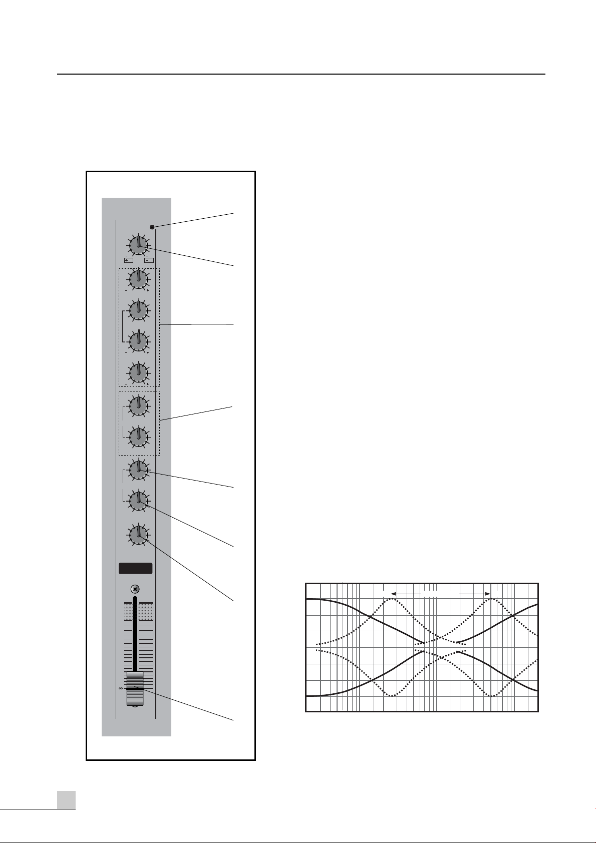
4. STEREO GRAPHIC EQUALIZER SECTION
The PX-1650 Series internal stereo graphic equalizer (GEQ) allows the fine response shaping of the
main program output. This section has seven linear controls, corresponding to center frequencies of
63Hz, 160Hz, 400Hz, 1kHz, 2.5kHz, 6.4kHz, 15kHz. Each control permits a maximum boost or cut of
12dB. When a control is set to the center or “0” position, the response in the corresponding band is
unaffected. The EQ switch turns the graphic equalizer on and off.
5. EFFECT RETURN CONTROLS
These controls adjust the levels of the signals that are received at the corresponding EFFECT RETURN jacks
on the top panel (or from the internal digital signal processor, when the DSP is used in place of external
input to the EFFECT RETURN 2 jacks). Each effect return circuit has two controls. The EFX 1, EFX 2 level
control adjusts the level of the signal that is mixed into the main program on the master mixing bus. The
EFX 1 to MON 1 control set the level of the signal that is mixed into monitor 1 bus, where it is mixed
with other signal for output by the monitor/out jacks on the top panel. The EFX 2 to MON 2 control used
same function as EFX 1 to MON 1 control but this control offer to DSP output signal, when you turn on
the DSP.
STEREO BUILT IN X-OVER
Meters Switch Up Switch Down
L/Monitor 1 Main L Output Monitor 1 Output
R/Monitor 2 Main R Output Monitor 2 Output
Output Switch Up Switch Down
Amp & Headphone Main L/R Monitor 1/2
PX-1650_E 2003.9.8 10:42 AM 페이지10

8PX-1650
6. MONITOR 1, 2 OUTPUT CONTROL
These controls adjust the overall output levels of the monitor mix that are setup using the monitor control
of each channel. The Monitor 1 or Monitor 2 mix signal are sent to the monitor output 1 and monitor out
2 jacks on the top panel. These controls should be used to optimally match the monitor mix output levels
to the input sensitivities of the power amplifiers used.
7. EFFECT SEND CONTROLS
These Control, adjust the overall output levels of the effect mixes that are set up using the EFFECT 1 and
EFFECT 2 controls of each input channel. The EFFECT SEND 1 Control sets the overall level of the signal
that appears at the EFFECT SEND 1 jack on the top panel. The EFFECT SEND 2 Control sets the overall
level of the Effect 2 mix signal, which is sent to both the EFFECT SEND 2 jack on the top panel and the
internal digital signal processor. These Control should be used to optimally match the effect mix output
levels to the input sensitivities of the effect signal processors used.
8. REC OUT AND TAPE IN CONTROLS
These controls adjust the levels of the stereo signals to and from a connected tape deck. The REC OUT
control sets the level of the unequalized pre-fader master mix signal that is sent for recording by the tape
deck via the REC OUT jacks on the top panel. The TAPE IN control adjusts the level of the playback
signal that is inserted to the master mixing bus from the TAPE IN jacks on the top panel. This playback
signal is added to the bus in front of GEQ, allowing the PX-1650 to equalizer the signal from the tape
deck before output.
9. PHONES CONTROL
This control adjusts the level of the stereo signal delivered from the PHONES jack located directly below
it on the front panel. Since this level adjustment is made after the GEQ, the volume of sound heard from
the headphones will be affected by both the master stereo faders and the PHONES control.
10. PHONES JACK
This jack delivers the main program signal to a pair of 40Ωstereo monitor headphones. The volume of
the output signal is adjusted by both the PHONES control and the master stereo faders.
11. MONO OUTPUT FADER
This fader adjusts the final level of the combined stereo signal and send the mono output jacks.
12. MASTER STEREO FADERS
These are the main volume controls for the overall program mix. They independently adjust the levels of
the right and left channels of the stereo signal that is sent to both the rear-panel SPEAKER jacks and the
GEQ PHONES jack on the front panel.
STEREO BUILT IN X-OVER
PX-1650_E 2003.9.8 10:42 AM 페이지11

9
PX-1650
Top Panel Controls
Top Panel Controls
* Phantom Power Warning
To prevent hazard or damage, connect only microphanes and cables that conform to the IEC268-15A
standard.
1. 2. CHANNEL INPUT CONNECTORS
Each of the PX-1650 input channel is provided with both a balance XLR connector (1) and a balance
tip-ring-sleeve 1/4” phone jack (2). The channel’s input signal is used to select between these input con-
nectors signal sources that don’t require phantom power should be connected to the phone jack (2)
when the phantom power on/off switch is turned on.
3. CHANNEL INSERT I/O JACK
Each input channel has a tip-ring-sleeve 1/4” phone jack that serves as an insert patch point for the
connection of external signal processing devices or other equipment between the channel’s head
amplifier (the first amplifier stage after input) and the EQ stage. The channel insertion point is ideal for
the insertion of a compressors, noise gate, equalizer, or other effect that needs to be applied to a
specific channel only. This jack accommodates both the send (output) and receive (input) lines required
by the insert point. The signals are sent and received at a nominal level of +0dB.
STEREO BUILT IN X-OVER
1
MIC
LINE
2
MIC
INSERT INSERTINSERT INSERT INSERT INSERTINSERT
LINE
3
MIC
LINE
4
MIC
LINE
5
MIC
LINE
6
MIC
LINE
SEND
RETURN
INSERT I 0
1
2
3
Line XLR Phone jack
GROUND Pin 1 Sleeve
HOT (+) Pin 2 Tip
COLD (-) Pin 3 Ring
Tip : Output (Send to external device)
Sleeve : Ground
Ring : Input (Return from external device)
PX-1650_E 2003.9.8 10:42 AM 페이지12

10 PX-1650
STEREO BUILT IN X-OVER
4. EFFECT RETURN JACKS
The output from external effect units fed by the EFFECT SEND jacks can be returned to the main program
mix via these 1/4” phone jacks. Note that both effect circuits have stereo EFFECT RETURN jacks,
allowing the PX-1650 to accommodate effect devices with stereo output. To return a monophonic effect
signal to both channels of the master stereo mixing bus, use the EFFECT RETURN jack (The R jack should
be left open). The levels of the signals input by these jacks are adjusted by the corresponding EFFECT
RETURN controls on the front panel. The nominal input level for these jacks is +4dB.
5. STEREO CHANNEL INPUT CONNECTORS
Each of the PX-1650 stereo input channel’s is provided with both a unbalanced 1/4” phone jack.
To return a monophonic signal to both channels of the master stereo mixing bus, use the stereo input L
jack (The R jack should be left open).
The nominal input level for these jacks is -20dB~+14dB.
6. MONO OUT JACKS
This phone jacks send the combined stereo signal.
The nominal output level for these jacks is +4dB.
7. LINE INSERT I/O JACKS
These tip-ring-sleeve 1/4” phone jacks serve as insert patch points for the connection of external signal
processing devices or other equipment to the master stereo mixing bus. These are two pairs of jacks,
allowing the devices to be connected both in front of and behind the GEQ. The line insertion points
are ideal for the insertion of stereo effects that need to be applied to the entire mix. These jacks
accommodate both send (output) and receive (input) lines required by the insert points. The signals are
sent and received at a nominal level of +4dB.
8. REC OUT AND TAPE IN JACKS
These phone jacks are used to send stereo signals (-10dBV) to and from a connected tape deck. The REC
OUT jacks send the unequalized pre-fader signal from the master bus for recording by the tape deck.
The TAPE IN jacks connect the playback signal from the tape deck to the master mixing bus in front of
the GEQ. The levels of these signals are adjusted by the REC OUT and TAPE IN controls on the front
panel.
ON
OFF
1
2
MONITOR OUT
+4dB
1
2
EFFECTSEND
+4dB
L
RPOST
GEQ
PRE
GEQ
STEREO INSERTL/R
L
R
L
R
1L
MONO
R
2L
MONO
R
MONO+4dB
R
L
MONO
R
L
MONO
13/14 15/16
EFFECT RETURN +4dB PHANTOM
POWER
STEREO
10dBV TAPE INREC OUT 10dBV
4
9
8
11
10
5
6
7
PX-1650_E 2003.9.8 10:42 AM 페이지13

11
PX-1650
STEREO BUILT IN X-OVER
9. PHANTOM POWER ON/OFF SWITCH
The PHANTOM ON/OFF switch turns the phantom power feature on and off. When turned on, this
function supplies +48V power to the positive and negative terminals of the balanced XLR connectors via
6.8kΩcurrent-limiting/isolation resistors for use by phantom-powered condenser microphones. Signal
sources that don’t require phantom power should be connected to the phone jack when phantom power
is used. The PHANTOM LED indicator lights when phantom power is on.
10. EFFECT SEND JACKS
These 1/4” phone jacks deliver the corresponding effect mix signals to feed external effect devices. Note
that the EFFECT SEND 2 output is active even when the internal digital signal processor is turned on. The
levels of the signals output by these jacks are adjusted by the corresponding EFFECT SEND controls on
the front panel. The nominal output level for these jacks is +4dB.
11. MONITOR OUT JACKS
These 1/4” phone jacks deliver the signal form the monitor mixing bus to feed external monitor speaker
systems driven by external amplifiers. Although both these jacks output the same monitor mix signal,
their output levels can be adjusted individually using the corresponding MONITOR output level controls
on the front panel. These jacks have a nominal output level of +4dB.
PX-1650_E 2003.9.8 10:42 AM 페이지14

12 PX-1650
STEREO BUILT IN X-OVER
Rear Panel Controls
Rear Panel Controls
1. POWER SWITCH
This switch turns the PX-1650 power supply on and off. The power LED on the front panel will light when
the power is on.
2. SPEAKER OUTPUT JACKS
These standard 1/4” phone jacks and speaker connect jacks are main speaker level output from the
PX-1650 power amplifier.
The PX-1650 Series provides four pairs of stereo speaker output jack, labeled 1, 2, 3 and 4. If you
connect a speaker system to only one of the jacks (SPEAKER 1 or SPEAKER 2 and SPEAKER 3 or
SPEAKER 4), the total load impedance of the speaker system may be as low as 4Ω. If you plug speakers
into both the phone jack and speaker connect jack of either channel, the minimum load impedance of
each speaker system is 8Ω.
3. MODE SELECTOR
X-over, By-pass or Bridge mono operation is chosen by the mode selector.
X-over: AMP 1 Output-High, AMP 2 Output-Low,
AMP 3 Output-High, AMP 4 Output-Low
You can use this mode when you accept the bi-amp method.
AMP 1 & 3 are used for high frequency and AMP 2 & 4 for low
frequency.
Bypass: Each channel signal does not pass through and operate independently (typical guard amplifier).
The AMP 1 output level and AMP 2 output level are adjusted by main left output fader. The AMP
3 output level and AMP 4 output level are adjusted by main right output fader in this mode. The
minimum speaker impedance per channel is 4Ω.
Bridge Mono: AMP 1 (AMP 1 + AMP 2), AMP 3 (AMP 3 + AMP 4)
In this mode, channels 1, 2 or 3, 4 are bridged together and work as one mono amplifier. You
can use 250 watt 4 channel as 500 watt 2 channel in this mode. The minimum speaker
impedance is 8Ω.
※CAUTION: When you change this mode, you must turn off the power switch for protecting speakers
from being damaged.
AMP 2 TRIM
6dB6dB
PUSH TO RESET
10A/250V AMP OUTPUT
AMP 4
4ΩMIN FOR EACH CHANNEL
POWER
AMP 3 AMP 2 AMP 1
AMP 4 AMP 3 AMP 2 AMP 1
3/4 1/2
X1
6dB
X-OVER OUTPUT
BRIDGED MONO
AMP 4 TRIM
6dB
X1
X-OVER FREQUENCY
BYPASS
60Hz
130 190
220
250Hz 60Hz
130 190
220
250Hz
X-OVER FREQUENCY
BRIDGED MONO
X-OVER
OFF
ON
AC INPUT
230V 50Hz
760W
~
AMP 3/4 AMP 1/2
HIGHLOWHIGHLOW
1 3
4
5
6
2
BYPASS
BRIDGED MONO
X-OVER
PX-1650_E 2003.9.8 10:42 AM 페이지15

13
PX-1650
STEREO BUILT IN X-OVER
4. FREQUENCY RANGE SELECTOR
Crossover frequencies from 60Hz to 250Hz or 600Hz to 2.5kHz respectively are chosen by the range
switch.
X1: 60Hz to 250Hz X10: 600Hz to 2.5kHz
5. CROSS FREQUENCY CONTROL
Crossover frequencies are set by adjusting the X-over frequency control.
The PX-1650 Processes 24dB/octave Roll-Off.
6. GAIN CONTROL
The Low-Output gain levels are selected by this control (-6dB to +6dB).
60Hz
130 190
220
250Hz
PX-1650_E 2003.9.8 10:42 AM 페이지16

14 PX-1650
STEREO BUILT IN X-OVER
Speaker Connections
Speaker Connections
BY-PASS 1
BY-PASS 2
AMP 2 TRIM
6dB6dB
PUSH TO RESET
10A/250 AMP OUTPUT
AMP 4
4ΩMIN FOR EACH CHANNEL
POWER
AMP 3 AMP 2 AMP 1
AMP 4 AMP 3 AMP 2 AMP 1
3/4 1/2
X1
6dB
X-OVER OUTPUT
BRIDGED MONO
AMP 4 TRIM
6dB
X1
X-OVER FREQUENCY
BYPASS
60Hz
130 190
220
250Hz 60Hz
130 190
220
250Hz
X-OVER FREQUENCY
BRIDGED MONO
X-OVER
OFF
ON
AC
INPUT
230V 50Hz
AMP 3/4 AMP 1/2
HIGHLOWHIGHLOW
BYPASS
BRIDGED MONO
X-OVER
※CAUTION: You must set the X-over switch to By-pass Mode.
PX-1650_E 2003.9.8 10:42 AM 페이지17

15
PX-1650
STEREO BUILT IN X-OVER
X-OVER 1
X-OVER 2
※CAUTION: When you apply to X-OVER MODE, you must connect correctly for protecting speakers from
being damaged. First, confirm output terminal on the rear panel of PX-1650, and then connect
tweeter speakers to CH1 & CH3 output and woofer speakers to CH2 & CH4 output.
※CAUTION: When you apply to X-OVER MODE, you must connect correctly for protecting speakers from
being damaged. First, confirm output terminal on the rear panel of PX-1650, and then connect
tweeter speakers to CH1 & CH3 output and woofer speakers to CH2 & CH4 output.
AMP 2 TRIM
6dB6dB
PUSH TO RESET
10A/250 AMP OUTPUT
AMP 4
4ΩMIN FOR EACH CHANNEL
POWER
AMP 3 AMP 2 AMP 1
AMP 4 AMP 3 AMP 2 AMP 1
3/4 1/2
X1
6dB
X-OVER OUTPUT
BRIDGED MONO
AMP 4 TRIM
6dB
X1
X-OVER FREQUENCY
BYPASS
60Hz
130 190
220
250Hz 60Hz
130 190
220
250Hz
X-OVER FREQUENCY
BRIDGED MONO
X-OVER
OFF
ON
AC
INPUT
230V 50Hz
AMP 3/4 AMP 1/2
HIGHLOWHIGHLOW
BYPASS
BRIDGED MONO
X-OVER
PX-1650_E 2003.9.8 10:42 AM 페이지18

16 PX-1650
STEREO BUILT IN X-OVER
BRIDGED MONO 1
※CAUTION: You must set the X-over switch to Bridged Mono and apply input to CH1, CH3.
BRIDGED MONO 2
AMP 2 TRIM
6dB6dB
PUSH TO RESET
12A/250V AMP OUTPUT
AMP 4
4‰ MIN FOR EACH CHANNEL
POWER
AMP 3 AMP 2 AMP 1
AMP 4 AMP 3 AMP 2 AMP 1
3/4 1/2
X1
6dB
X-OVER OUTPUT
BRIDGED MONO
AMP 4 TRIM
6dB
X1
X-OVER FREQUENCY
BYPASS
60Hz
130 190
220
250Hz 60Hz
130 190
220
250Hz
X-OVER FREQUENCY
BRIDGED MONO
X-OVER
OFF
ON
AMP 3/4 AMP 1/2
HIGHLOWHIGHLOW
BYPASS
BRIDGED MONO
X-OVER
STEREO MODE
AMP OUTPUT CH 1, CH 2(4‰)
NOT CONNECTED
BRIDGED MONO MODE
(COLD) (HOT)
AMP OUTPUT CH 1 OR CH 3(8‰)
NOT CONNECTED
SPEAKON CONNECTION
11
2
21
12
2
AMP 2 TRIM
6dB6dB
PUSH TO RESET
10A/250 AMP OUTPUT
AMP 4
4ΩMIN FOR EACH CHANNEL
POWER
AMP 3 AMP 2 AMP 1
AMP 4 AMP 3 AMP 2 AMP 1
3/4 1/2
X1
6dB
X-OVER OUTPUT
BRIDGED MONO
AMP 4 TRIM
6dB
X1
X-OVER FREQUENCY
BYPASS
60Hz
130 190
220
250Hz 60Hz
130 190
220
250Hz
X-OVER FREQUENCY
BRIDGED MONO
X-OVER
OFF
ON
AC
INPUT
230V 50Hz
AMP 3/4 AMP 1/2
HIGHLOWHIGHLOW
STEREO MODE
AMP OUTPUT CH 1, CH 2(4‰)
NOT CONNECTED
BRIDGED MONO
AMP OUTPUT CH 1 OR CH 3(8‰)
NOT
SPEAKON CONNECTION
11
2
21
12
2
BYPASS
BRIDGED MONO
X-OVER
PX-1650_E 2003.9.8 11:38 AM 페이지19

17
PX-1650
STEREO BUILT IN X-OVER
Operating Tips
Operating Tips
※CAUTIONS FOR CONNECTED SOURCES
Please observe the following cautions when connecting sound sources to the PX-1650.
- TURN THE POWER OFF FIRST
Always make sure that the mixer’s POWER switch is turned off before connecting or disconnecting any
cables. Failure to do so can damage the PX-1650 or connected equipment.
- TURN THE MIXER ON LAST
Always turn the mixer’s POWER switch on after first turning on connected sound sources such as electron-
ic instruments or audio equipment.
- DO NOT CONNECT AMPLIFIED INPUT
Never connect the speaker-level output of any amplifier to the mixer’s inputs unless you use a suitable
high-level attenuation pad or “direct box” to lower the signal’s level.
※MATCHING INPUT LEVELS
When matching input levels, it is a good idea to first make sure that the speaker systems are disconnected
from the mixer’s speaker outputs (This must be done with the mixer’s POWER switch turned off.). The sound
can be monitored using a pair of headphones plugged into the front-panel PHONES jack-but make sure
that the master stereo faders are set to their minimum levels as first, then raise them just enough to produce
a comfortable sound level when you actually begin monitoring input signals and matching levels.
Once all your sources are connected and the entire system is turned on, it is important to accurately match
the input sensitivity of each input channel with the source signal it will receive. Do this one channel at a
time. Begin by setting the lowest possible sensitivity for the input. Set the GAIN control to -16, and slide the
channel fader to between “10” and “5” on its scale.
Now apply a signal to the input. Play the connected source instrument at the loudest level it will produce in
actual use-or if the source is a microphone, have the vocalist sing his or her loudest note into it-and watch
the channel’s PEAK indicator carefully. If it lights at this point, the output level of the source must be reduced.
Normally, however, you will have to increase the input sensitivity to achieve optimum matching.
Gradually increase the setting of the GAIN control until the PEAK indicator just barely flashes on the loud-
est peaks. If you turn the GAIN control up all the way and the PEAK indicator still does not light, then
reduce the GAIN control setting to minimum, and gradually increase the GAIN setting again. This time the
PEAK indicator should light somewhere in the GAIN control range. If it does not, check that the source is
functioning properly and that it is properly connected to the appropriate input of the mixer. You may also
want to check the connecting cable for faults.
Since the PEAK indicator lights when the channel signal is 3dB below the clipping level, it is okay if it flash-
es briefly on loud peaks. In fact, this is about the optimum input sensitivity setting. When you’ve matched
the first channel, set its fader to minimum and begin matching the next channel. Repeat this procedure for
each channel you will use in the mix.
Once the input level of each channel has been matched, set the master stereo faders to their minimum posi-
tions and turn the POWER switch off. Reconnect the speaker systems, then turn the power back on. The
master faders can now be gradually raised to their operating levels.
PX-1650_E 2003.9.8 10:42 AM 페이지20

18 PX-1650
STEREO BUILT IN X-OVER
※SETTING CHANNEL AND MASTER FADERS
The final positions of the channel faders will naturally depend on the overall mix you set up. However,
there are two important points you should keep in mind when setting channel levels.
The channel faders have an optimum range that provides the maximum control margin with minimum noise
and distortion. The optimum range for the channel faders on the PX-1650 is between about “5” and “15”
on their scales. There is no rule that says you must avoid higher or lower settings, but remember that the
best sound quality can be achieved within this range. Settings in this range also provide sufficient leeway
for later adjustments.
Remember, too, that changing the setting of any single input channel fader will affect the overall output
level. This is way it is important to watch the level meters when setting the input channel and master stereo
faders. These meters should never read levels higher than about 0 VU. If they do, then the mixer levels are
too high and the power amplifier may be overloaded, causing distortion.
It is generally best to use the master stereo faders when making small adjustments to the overall output
level. But if these faders must be set to extremely low or high positions (lower than about “20” or higher
than “5” on their scales), then the overall mix should be re-adjusted using the input channel faders so that
the level meters show a proper level when the master stereos are set within the range described above.
※USING THE CHANNEL EQUALIZERS
Each of the PX-1650 input channels has four equalizer (EQ) controls that make it possible to independently
equalize the channel’s signal to some degree. The rule of thumb, however, is that equalization should not
be used unless it is absolutely necessary. Always put some effort into proper microphone selection, careful
microphone placement, and fine adjustment of source instrument controls before resorting to equalization.
Settle for this option only if you have set everything up as best you can and are still not satisfied with the
sound.
Channel equalization can be most useful in tonally separating on sound from another, or from a group of
sounds, Slightly boosting the high frequency of a guitar sound, for example, can give it the extra bite it
needs to stand out more clearly from the background. Vocals tend to stand out better if given a bit of boost
in the middle range. Speech generally benefits from a reduction in the low frequencies, to prevent the
“boomy” sound that occurs when the speaker gets too close to the microphone. Experimentation and
experience will tell you how much of what type of equalization is appropriate for different sound sources.
Also keep in mind the fact that the channel’s PEAK LED indicator is post-EQ. Excessive boosting of a signal
frequency may cause the PEAK LED to light more than briefly, indicating that you need to either reduce the
input gain or reduce the amount of boost being applied.
PX-1650_E 2003.9.8 10:42 AM 페이지21
Table of contents
Other Inter-m Dj Equipment manuals