Interchange MD8 Series User manual

MD8 Dryer
by Interchange
Operating Manual
Job No…………………….
Year……………………….2016
90 Dayton Avenue Passaic, New Jersey 07055 • Ph: 973.473.5005 • Fx: 973.473.4485 • Sales: 800.822.5457 • Web: www.interchangecorp.com
1

Dear New Customer:
At Interchange we strive to achieve 100% customer satisfaction. By providing our customer with a quality
product combined with professional service and support, we believe this goal can be accomplished.
We would like to thank you for your recent purchase and welcome your comments on the overall experience
with our company.
At anytime, please feel free to contact any the following people with your questions, comments or open issues:
Parts & Service.......….. Todd Salute—ext. 13 todd@interchangecorp.com
Accounting– ext 14 [email protected]
We hope your experience with Interchange met all of your expectations. If not, we stand ready to rectify any
open situation and achieve our goal of 100% customer satisfaction. Once again, thank you for your business.
Sincerely,
Interchange Equipment, Inc.
Marc Herrmann
President
90 Dayton Avenue Passaic, New Jersey 07055 • Ph: 973.473.5005 • Fx: 973.473.4485 • Sales: 800.822.5457 • Web: www.interchangecorp.com
2

Equipment Solutions for Specific Requirements
www.interchangecorp.com
SPECIFICATIONS
MD 8
by Interchange
oInfra-red panel
o Cooling sections
o Additional conveyor sections
o Hi-Temp feature - up to 450º
o Electric hot air burner
o Automatic Doffing System for flat goods
oUV curing capability with vacuum hold down
oSplit belts with independent speed adjustments
OPTIONAL FEATURES
MODEL REF BELT SIZE A C
3608 IN 36 70 45
6008 IN 60 97 69
Gas Type: Natural or propane 6—12” WC 3/4”
NPT Electric: 208—230 Volt, 3 Phase 15 Amp
4808 IN 48 82 57
90 Dayton Avenue -Passaic, N.J. 07055 Tel: (973) 473-5005 Fax: (973) 473-4485
16' OVERALL LENGTH
A
C
32"
250,000 BTU Rated Burner
3HP Motor/4500 CFM
Exhaust Connection
8' C HAMBER
3/4" Gas
Connection
3

General Installation Instructions:
Dryer to be positioned no closer than 12 inches
from wall.
No special Flooring is required.
Dryer must be vented prior to Start-Up.
Utility Hook-ups must conform to local codes.
Dryer produced under UL Code 795, Fourth
Addition-Commercial Industrial Gas Heating
Equipment.
208/230 3 Phase 15.5 FLA
Gas @ 3/4" NPT @ 6-11" WFC
Optional IR Panel
Infeed
208/230 3 Phase 17.5 FLA
IR
4 Foot Standard
6Footw/IR
MD-8
Site Installation
Customer Supplied Ductwork
Dryer equipped with a 6" Exhaust Hook-
Up Connection.
6" Exhaust Duct Customer Installed
4

Exhaust Requirements MD8 Series Dryers
MD 8 Series dryers are produced under the UL Code 795, Fourth Addition –
Commercial Industrial Gas Heating Equipment. The dryer is also listed under ETL
compliance with the same and has a reference number of J98*10442. All utility hook
ups and exhaust connections should comply with these codes.
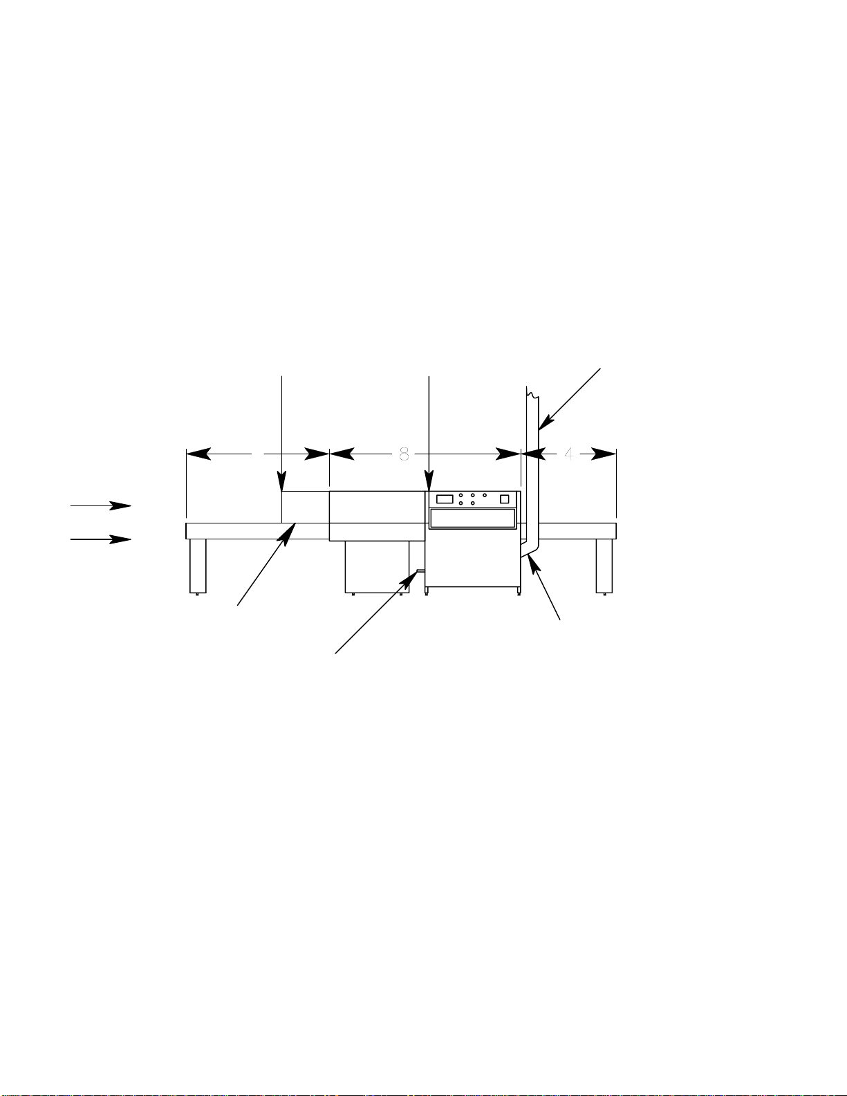
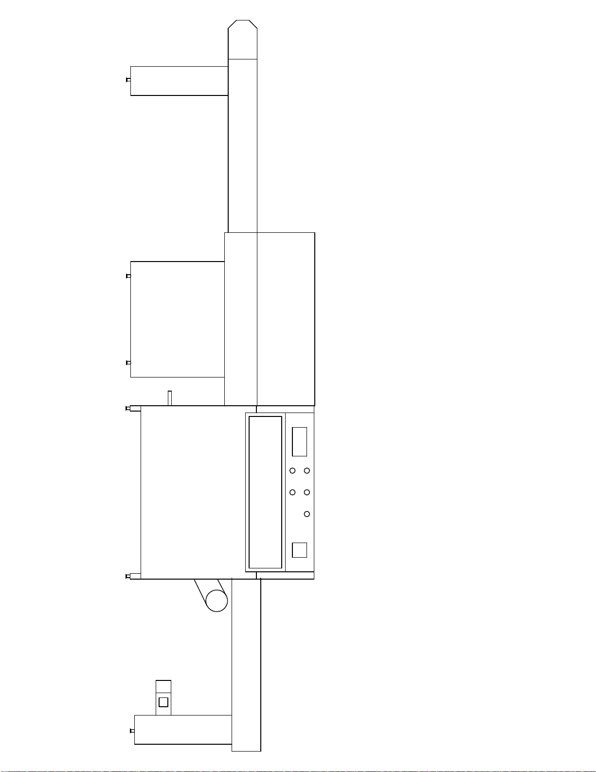
The MD8 is supplied with a 6 inch exhaust duct connection point. Connect 6 inch single
wall or double wall ventilation piping. Please consult your local city and/or state code to
determine which type of ventilation piping is required.
If the ventilation piping travels a distance of over 30 feet from the initial connection
point or if there are more than two 90 degree bends in the total run on the ventilation
piping, a booster blower may be required. It is necessary to maintain 350 - 500
CFM Maximum Exhaust Capacity (12 -17 M3 / Minute Maximum) at connection
point. Exhausting air temperature after 15 ft is approximately 200F. (95C)
90 Dayton Ave Passaic, NJ 07055 USA • PH 973.474.5005 FX 973.473.4485 • www.interchangecorp.com
5

Infeed
Heat
Extension
Assembley Instructions
MD8 36-48-60
Exit
Burner
6

! !
!
!" #$%&'$()$*+($,+$-./&-(0#&%(.1/2"
*" 34*5$(0.(*.(3/5+6#$2(*7&'$"(
7" 3*..(0.(5&%34$+$8(6-2$#-$*+)(
+)$(7*.$"(
9" #$%&'$(76#-$#(7*.$(0#&%(.1/2"
*" 34*5$(0.(6-2$#(4/3(&0(76#-$#(7*.$"
7" 4/0+(*-2(34*5$(74&51(6-2$#(76#-$#(7*.$"
5" /-.$#+(0.(5&%34$+$48(6-2$#(76#-$#
7*.$"
:" 34*5$(76#-$#(7*.$(/-(2$./#$2(4&5*+/&-"
;" 6./-<(*(!;=!>?(@#$-5)A(4$'$4(+)$(2#8$#(78
*2B6.+/-<(+)$(B*51/-<(7&4+."($-.6#$(2#8$#(/.
#*/.$2(*+(4$*.+(C?(@/+)(B*51/-<(7&4+."((+)/.
@/44(#$265$('/7#*+/&-"
D" 2#8$#(/.(-6%7$#$2(-6%$#/5*448(.+*#+/-<
0#&%(/-0$$2(+&($,/+"((@)$-(.+*-2/-<(*+
+)$(5&-+#&4(3*-$4(E76#-$#(.$5+/&-FA(+)$
/-0$$2(*-2()$*+($,+$-./&-(*#$(+&(+)$
4$0+(*-2(+)$($,/+(/.(+&(+)$(#/<)+"
>" %&6-+(+)$($,)*6.+(2*%3$#(<*+$(+&(+)$
3#$G2#/44$2()&4$.(&-(+)$($,/+($-2(&0(+)$
76#-$#(.$5+/&-"()*#2@*#$(/.(/-5462$2"
STEP%1:%MECHANICAL%INSTALLATION%
Installation Procedure
7

H" %&6-+($,/+(E+)/.(/.(+)$($,+$-+/&-(@/+)(+)$
%&+&#F(+&(76#-$#(7*.$(*-2(4$'$4(6./-<
+)$(B*51/-<(7&4+."
I" %&6-+(*2B6.+*74$()&&2(<*+$(+&(+)$(76#-$#"
4/0+(<*+$(+&(+)$(7&++&%(&0(+)$(.4&+(+&
%*,/%/J$(54$*#$-5$"(*2B6.+(*55/-<48
@)$-(/-(6.$"
K" 5&--$5+(+)$($,/+(%&+&#(346<(+&(+)$(%*/-
3*-$4(78(%*+5)/-<(+)$(-6%7$#."
!L" 6-@/-2(7$4+(*-2(7$</-(+&(3*..(/+(+)#&6<)
+)$(7&++&%(*-2(+&3(.633&#+.(&-($,/+(*-2
76#-$#(7*.$"
*" +&3(&0(7$4+()*.(5&--$5+/-<(%$+*4(
.+#/3.(@)/4$(7&++&%(&0(7$4+()*.(
.$3*#*+$('$#+/54$(.+#/3."(
!!" %&'$()$*+($,+$-./&-(/-+&(3&.+/&-(4$*'/-<(*(9(0+"
.3*5$(/-($#(+&(5&-+/-6$(+&(0$$2(+)$(7$4+
+)#&6<)(+)$(2#8$#"
!9" 7#/-<(7$4+(+)#&6<)()$*+($,+$-./&-(+&3(*-2
7&++&%(7$4+(.633&#+."
+&3(&0(
7$4+M(
7&++&%(
&0(7$4+M(
Installation Procedure
8

!"
!:" %&'$()$*+($,+$-./&-(/-+&(3&./+/&-(*-2
4$'$4(+&(76#-$#(7*.$"
!D" .$56#$(4*+5)$.(7$+@$$-(76#-$#(*-2()$*+($,+$-./&-"
3$#/&2/5*448(#$*2B6.+(*-2(+/<)+$-(*44(4*+5)$.(*.
+*23&4$(.$*4*-+(7$</-.(+&(.&0+$-(0#&%()$*+"(+)$
+/<)+$#(+)$(4*+5)$.(*#$(+)$(4$..()$*+(4$*1*<$(+)$#$
@/44(7$"
!;" %&6-+(/-0$$2(E+)/.(/.(+)$($,+$-./&-
@/+)&6+(+)$(%&+&#F(+&(+)$()$*+
$,+$-./&-(*-2(4$'$4"
!>" 0$$2(#$%*/-/-<(7$4+(+)#&6<)(/-0$$2(*-2(5&--$5+(.34/5$
6./-<(-$$24$(-&.$(348$#.(+&(+)#$*2(%$+*4(3/-"
*" 5&-0/#%(+&3(&0(7$4+(7$0&#$(/-.+*44/-<(E.$$(N!LF
7" 56+($,5$..(%$+*4(3/-(/0(-$5$..*#8"
!I"
&-5$(2#8$#(/-+.+*44*+/&-(/.(5&%34$+$ *-2
4$'$4$2A(4*<(/-0$$2(*-2($,/+(4$<. +&(+)$(04&&#
@/+)(7#*51$+(3#&'/2$2 &-($*5)(4EG. PRIOR TO
LAGGING, ENSURE INFEED AND EXIT ARE SQUARE
TO THE DRYER BASE
Installation Procedure
9

!" *(5$#+/0/$2(346%7$#(*-2=&#($4$5+#/5/*-
%6.+(3$#0&#%(*44(5&--$5+/&-."(5&--$5+
3&@$#(.63348(+&(2#8$#(E.$$(*7&'$F"(+)$
.3$5(34*+$(4&5*+$2(&-(4$0+(./2$(&0(%*/-
5&-+#&4(3*-$4()*.(6+/4/+8(/-0&#%*+/&-"
STEP%2:%ELECTRICAL%&%GAS%CONNECTIONS%
9" 5&--$5+(:=D?(<*.(.63348(+&(2#8$#"
.$$(.3$5(34*+$(4&5*+$2(&-(4$0+(./2$(&0
%*/-(5&-+#&4(3*-$4"
:" +6#-(%*/-(3&@$#(&-(0#&%(+)$
$4$5+#/5/*-(.6334/$2(06.$(7&,(&#
2/.5&--$5+(7&,"(+)$(7$4+(@/44(-&@
7$/-<(+&(.+*#+(#6--/-<"
D" +6#-(%*/-(74&@$#(&-(*-2(+)$-
&00(+&(5)$51(#&+*+/&-(&0(%*/-
74&@$#"(2/#$5+/&-(.)&642(%*+5)
*##&@"
STEP%3:%START%UP%&%BELT%TRACKING%
!" +6#-(3&@$#(&-(+&(2#8$#"
9" +6#-(7$4+(.3$$2(3&+$-+/&%$+$#(1-&7(+&
%/-/%6%"
:" *2B6.+(7$4+(+$-./&-(*-2(7$</-(+#*51/-<
7$4+"((.$$(%*-6*4(0&#(/-.+#65+/&-."
D" .+*#+(2#8$#(@/+)()$*+"((.$$(%*-6*4(0&#
/-.+#65+/&-."
;" 5&-+/-6$(+&(5)$51(7$4+(+#*51/-<(@/+)
)$*+(*.(4&-<(*.(-$5$..*#8(+&(3#$'$-+
2*%<$(+&(7$4+"
<#&6-2(
TOOLS%NEEDED%FOR%INSTALLATION%
!" 0(4/0+(O(#$5&%%$-2$2
9" 36%3(B*51(O(/0(0/0+(-&+(*'*/4*74$
:" 3#87*#(=()*%%$#
D" D?(,(>?(74&51(&0(@&&2
;" ;=!>?(&3$-($-2(@#$-5)
>" I=!>?(&3$-($-2(@#$-5)(=(.&51$+
I" K=!>?(&3$-($-2(@#$-5)(=(.&51$+
H" ;=H?(&3$-($-2(@#$-5)(=(.&51$+
K" !;=!>?(&3$-($-2(@#$-5)(=(.&51$+
!L" 3)/44/3.()$*2(.5#$@(2#/'$#
!!" -$$24$(-&.$(34/$#.
!9" 2#/44(0&#(.$56#/-<(2#8$#($,+$-./&-
4$<.(+&(04&&#
re10
Installation Procedure
10

OPERATIONS INSTRUCTIONS
MD8 INTERCHANGE EQUIPMENT, INC.
1. Blower on—Push Button
2. Blower off—Push and Hold Button for 3 seconds
START DRYER:
Blower must be on—
Turn burner switch to right and hold until blue purge light illuminates.
Set temperature on controller by using the up and down arrows. (start at 350 degree).
Set belt speed to the desired dwell time. This is dependent upon many factors; ink type
material type/color and product type. Consult your ink supplier to determine exact ink
requirements.
To turn off - turn burner switch to left. This will turn off heat (gas or electric). Blower will
time out (remain on) for 10 minutes and then shut down. The belt will continue to run as
long as power is supplied to dryer. After blower has timed out, power may now be
disconnected from dryer.
Operating Instruction
11

BELT TRACKING
MD8INTERCHANGE EQUIPMENT, INC.
1. If your MD8 is equipped with the "Belt Sensor" tracking system, supply the system
with 70-80 psi of compressed air. Belt tracking is very important, and all tracking
systems must be monitored especially during the break-in period.
2. Check that the tracking arm is centered between the two jacking bolts. Bolts should
only be hand tight (see Figure c).
3. Center Belt on infeed and exit roll. Adjust belt proximity switch to read edge of belt,
then move back ¼".
4. Remove slack from belt using adjustment bolts until belt has a uniform tension.
(Too much tension can cause belt failure, do not over tighten.)
5. Turn conveyor switch to on position. Turn speed to a minimum. Belt sensor switch
must not be reading the belt. When the switch does not read the belt, the tracking
cylinder is extended causing the belt to walk towards the belt sensor switch. The belt
should always walk towards the switch.
6. Slowly increase speed to determine which way the belt is walking. If belt is walking
away from proximity switch, loosen jacking bolt A; this will further extend the tracking
cylinder causing the belt to walk towards the proximity switch.
7. When the switch reads edge of belt for a constant 2 seconds, the cylinder will retract
which will cause the belt to walk away from the switch. If this does not happen,
loosen jacking bolt B; this will allow the cylinder to further retract.
8. Adjust the position of the switch (by rotating rod in or out) to control how the belt
centers on the main rollers.
9. When adjusted correctly, belt movement is very slow and steady. If belt moves left
and right too rapidly, adjust jacking bolts A&B to slow movement down.
Belt Tracking
12

SETUP INSTRUCTIONS
FIGURE A
Feed String thru Dryer
SETUP INSTRUCTIONS
FIGURE B
MD 8
INTERCHANGE EQUIPMENT, INC.
Belt thru Tracking Rolls
for auto tracking option Balt Tracking
13

BELT TRACKING
FIGURE C
Adjustment
Bolts
Jacking Bolt B -
optional Auto Tracking
Top View Tracking System
Jacking
Bolt A - optional Auto
Tracking
MD8
INTERCHANGE EQUIPMENT, INC.
Balt Tracking
14

DRYERBELTREPLACEMENTINSTRUCTIONS
1. TurnConveyoronandbringBeltSplicearoundtothetopoftheInfeed
Drum.Shutdryeroff.
2. MarktheInfeedTakeUpPlatessoyoucantensiontheNewbeltthesame
asyouroldBelt.Thiswillgiveyouagreatstartingpointforre‐trackingthe
belttoo.Itmaybethatnootheradjustmentisnecessary.
3. LoosenthetensionofthebeltbyusingtheTakeUpPlateAdjustment
ScrewsoninsideofInfeedRails.
4. RemovetheAlligatorSpliceConnectingPin.Ifdifficult,workeachsideof
BeltSplicebackandforthtohelploosenupzipperandpinandtryagain.
5. TakenewBeltandconnectAlligatorSplicewithOldBeltAlligatorSplice.
UsetheOldBelttopulltheNewBeltthroughtheentiredryer.Removethe
OldBeltfromtheNewBelt.
6. AlignAlligatorSplicecorrectlyandinstallnewConnectingPinonNewBelt
joiningsplicetogether.
7. TensionTakeUpPlatestomarksmadeasnotedinStep1.
8. TurnConveyoronmediumspeedandseeifbeltistrackingproperly.Ifok,
tighten4LockdownBoltsoneachsideoftheInfeedRail.Ifnot,make
necessaryadjustmentsusingtheInfeedTakeUpPlateadjustmentsthen
tighten4LockdownBoltsoneachsideoftheInfeedRail.
9. Startdryerwithheatandmonitorbeltcloselyforthefirsthourand
continuetocheckthroughouttheday.Thebeltshaveatendencytomove
astheybegintobreakinandsoftenfromtheheat.
Belt Replacement
15

AUTO TUNING GAS
Setting Parameters
1. Push button #1 to Access Menu (Ac.Cd will flash, then menu # will flash).
2. Use arrow buttons to get to correct menu.
3. Once in correct menu, use button #1 to scroll through menu to view parameters.
4. Use arrow buttons to change parameters.
MENU 03 MENU 05
CY.t1 00 SnSr J
SP.tt off OUt1 Ht.P
LSP.L 0 OUt2 Alr
USP.L 500 Unlt F
1. Blowers on.
2. Push arrow buttons to set SV (set value) 350° F.
3. Push Button #4 and hold until “Tune” flashes— once flashes then release.
4. Turn burner \ heat switch to ON—(switch will return to center).
5. Auto Tune will begin.
5. When "Tune" stops flashing, procedure is complete.
NOTE:
•Dryer must be ambient temperature before auto tune.
•If dryer is double burner, do both sections at same time.
•When all is set and working correctly, put controller into Menu 01. This allows only the
changing of SV. Once in menu 01, button #1 must be depressed for a full 30 seconds to
access other menus.
MD8 INTERCHANGE EQUIPMENT, INC.
Temperature Control
4—20 MA
AUTO TUNING
Gas Autotuning
16

AUTO TUNING—I/R SECTION
IF APPLICABLE
Setting Parameters
1. Push button #1 to Access Menu (Ac.Cd will flash, then menu # will flash).
2. Use arrow buttons to get to correct menu.
3. Once in correct menu, use button #1 to scroll through menu to view parameters.
4. Use arrow buttons to change parameters.
MENU 03 MENU 05
CY.t1 15 SnSr K(cA)
SP.tt off OUt1 Ht.P
LSP.L 0 OUt2 ALr
USP.L 1000 Unlt F
1. Main burner must have flame on.
2. Set IR selector switch to OFF.
3. Push button #4 and hold until “STBY” flashes—then release.
4. Push arrow buttons to set SV to 600° F.
5. Push Button #4 and hold it until “TUNE” flashes—then release.
6. Turn selector switch to ON—Auto Tune will begin.
5. When tune stops flashing, procedure is complete.
NOTE:
!Dryer must be ambient temperature before auto tune.
!When all is set and working correctly, put controller into Menu 01. This allows only the chang-
ing of SV. Once in menu 01, button #1 must be depressed for a full 30 seconds to access
other menus.
AIRJETINTERCHANGE EQUIPMENT, INC.
Temperature Control
Infared Autotuning
17

1. BLOWERS ON
2. PUSH ARROWS TO SET SV TO 300 DEG. F
3. PUSH BUTTON #4 & HOLD IT IN UNTIL "TUNE" FLASHES, THEN
RELEASE.
4. TURN BURNER\HEAT SWITCH TO ON (SWITCH WILL RETURN TO CENTER)
5. AT THIS POINT AUTO TUNING WILL BEGIN. WHEN TUNE
STOPS FLASHING,PROCEDURE IS COMPLETE.
*NOTE* DRYER MUST BE AT AMBIENT TEMP. BEFORE AUTO TUNE
*NOTE* IF DRYER IS A DOUBLE BURNER,DO BOTH SECTIONS AT SAME
TIME.
*NOTE* WHEN ALL IS SET & WORKING CORRECTLY,PUT CONTROLLER
INTO MENU 01. THIS ALLOWS ONLY THE CHANGING OF SV.
ONCE IN MENU O1,BUTTON #1 MUST BE DEPRESSED FOR
AFULL30SEC.TOACCESSOTHERMENUS.
PUSH BUTTON #1 TO ACCESS MENU (Ac.Cd will flash, then menu # will flash) USE ARROW BUTTONS TO
GET TO CORRECT MENU.
ONCE IN CORRECT MENU, USE BUTTON #1 TO SCROLL THROUGH
MENU TO VIEW PARAMETERS.USE ARROW BUTTONS TO CHANGE PARAMETERS.
MENU 03 MENU 05
CY.t1 15 SnSr J
SP.tt off OUt1 Ht.P
LSP.L 0 OUt2 ALr
USP.L 500 UnIt F
SETTING PARAMETERS
AUTO TUNING
234
P
V
S
V
ATHENA
85
300
TEMPERATURE CONTROL
1
AUTO TUNING FOR
ELECTRIC HOT AIR MD8
Electric Autotuning
18

MD-8 GAS FIRED MODEL MAINTENANCE
1. Grease the bearings on the blower fan drive shaft (with high
temperature grease only),every 200 operating hours or once a month
depending on your production level. They are located on either side of the
burner section under the heat extensions.
2. Grease the shaft and conveyor bearings (with standard grease) every
200 operating hours or once a month depending on your production level.
Check oil level in belt speed reducer every 4 to 5 months or every 300
operating hours.
3. Check belt drive brushes every 600 operating hours.
4. If the dryer is equipped with "Belt Sensor" switch, check the operation of
cylinder for smooth operation. This is important to keep the belt tracking
working properly.
5. The dryer is equipped with lint filters which are located on the rear of the
dryer for easy access. They should be cleaned at least once a week along with
recirculation blower blades.
(depending on your production level). Check daily until a schedule can be
determined.
6. We recommend checking the inside of the dryer for buildup of dust and
debris. This can easily be accomplished by un-latching the exhaust hoods
and checking the inside of the hoods. The burner section can be checked
by opening the door located under the filters. Every application is different,
so there is no set schedule. Check monthly until a schedule can be
determine.
7. Inspect Blower Motor Pulley Belt damage. Tension if necessary.
8. Inspect and clean Flamerods and Igniter at Burner Basket location with a fine
grit sandpaper quarterly. Also inspect and replace if necessary, all related
wiring.
9. Inspect and clean or replace Main Panel Cooling Fan Filter periodically
NOTE:
It is very important to keep the entire dryer clean. If lint is allowed to
build up, the
efficiency and drying capabilities will be greatly diminished.
Maintenance
19

MD-8 ELECTRIC FIRED MODEL MAINTENANCE
1. Grease the bearings on the blower fan drive shaft (with high
temperature grease only),every 200 operating hours or once a month
depending on your production level. They are located on either side of the
burner section under the heat extensions.
2. Grease the shaft and conveyor bearings (with standard grease) every
200 operating hours or once a month depending on your production level.
Check oil level in belt speed reducer every 4 to 5 months or every 300
operating hours.
3. Check belt drive brushes every 600 operating hours.
4. If the dryer is equipped with "Belt Sensor" switch, check the operation of
cylinder for smooth operation. This is important to keep the belt tracking
working properly.
5. The dryer is equipped with lint filters which are located on the rear of the
dryer for easy access. They should be cleaned at least once a week
(depending on your production level). Check daily until a schedule can be
determined.
6. We recommend checking the inside of the dryer for buildup of dust and
debris. This can easily be accomplished by un-latching the exhaust hoods
and checking the inside of the hoods. The burner section can be checked
by opening the door located under the filters. Every application is different,
so there is no set schedule. Check monthly until a schedule can be
determine.
7. Inspect Blower Motor Pulley Belt damage. Tension if necessary.
8. Inspect wires and connections on Duct Heaters.
9. Inspect and clean or replace Main Panel Cooling Fan Filter periodically
NOTE:
It is very important to keep the entire dryer clean. If lint is allowed to
build up, the
efficiency and drying capabilities will be greatly diminished.
Maintenance
20
This manual suits for next models
3
Table of contents
Popular Dryer manuals by other brands

Siemens
Siemens WQ33G2D0GR User manual and installation instructions

AEG
AEG LAVATHERM T3DBN79V user manual

PITSOS
PITSOS wtp60100 Operating and installation instruction

Alliance Laundry Systems
Alliance Laundry Systems LEB07A*-1709 Service manual

Beko
Beko DSY10PB46W user manual

Smeg
Smeg DRY72C-1 Instructions for use