ADC AD-30x2 Series User manual

AD-30x2(R)(i)
Installation Manual
ADC Part No. 113019-7
WARNING: For your safety the
information in this manual must be
followed to minimize the risk of fire or
explosion and to prevent property
damage, personal injury or death.
—Do not store or use gasoline or other
flammable vapors and liquids in the
vicinity of this or any other appliance.
—WHAT TO DO IF YOU SMELL GAS:
●Do not try to light any appliance.
●Do not touch any electrical switch;
do not use any phone in your
building.
●Clear the room, building or area of
all occupants.
●Immediately call your gas supplier
from a neighbor’s phone. Follow
the gas supplier’s instructions.
●If you cannot reach your gas
supplier, call the fire department.
—Installation and service must be
performed by a qualified installer,
service agency or the gas supplier.
AVERTISSEMENT: Assurez-vous de
bien suivre les instructions données dans
cette notice pour réduire au minimum le
risque d’incendie ou d’explosion ou pour
éviter tout dommage matériel, toute
blessure ou la mort.
—Ne pas entreposer ni utiliser d’essence
ni d’autres vapeurs ou liquides
inflammables à proximité de cet
appareil ou de tout autre appareil.
—QUE FAIRE SI VOUS SENTEZ UNE
ODEUR DE GAZ:
●Ne pas tenter d’allumer d’appareils.
●Ne touchez à aucun interrupteur. Ne
pas vous servir des téléphones se
trouvant dans le bâtiment.
●Évacuez la pièce, le bâtiment ou la
zone.
●Appelez immédiatement votre
fournisseur de gaz depuis un voisin.
Suivez les instructions du fournisseur.
●Si vous ne pouvez rejoindre le
fournisseur de gaz, appelez le service
des incendies.
—L’installation et l’entretien doivent être
assurés par un installateur ou un
service d’entretien qualifié ou par le
fournisseur de gaz.
American Dryer Corporation
88 Currant Road
Fall River MA 02720-4781 USA
Telephone: +1 (508) 678-9000 / Fax: +1 (508) 678-9447
e-mail: techsupport@amdry.com
www.adclaundry.com

2American Dryer Corp. 113019-7
“IMPORTANT NOTE TO PURCHASER”
Information must be obtained from your local gas supplier on the
instructions to be followed if the user smells gas. These
instructions must be posted in a prominent location near the dryer.
FOR YOUR SAFETY
Do not store or use gasoline
or other flammable vapors
and liquids in the vicinity of
this or any other appliance.
POUR VOTRE SÉCURITÉ
Ne pas entreposer ni utiliser d’essence
ni d’autres vapeurs ou liquides
inflammables à proximité de cet
appareil ou de tout autre appareil.
We have tried to make this manual as complete as possible and hope you will find it useful. The manufacturer
reserves the right to make changes from time to time, without notice or obligation, in prices, specifications, colors, and
material, and to change or discontinue models. The illustrations included in this manual may not depict your particular
dryer exactly.
IMPORTANT
For your convenience, log the following information:
DATE OF PURCHASE ________________________________________________ MODEL NO. ______________________
RESELLER’S NAME __________________________________________________________________________________
SERIAL NUMBER(S) __________________________________________________________________________________
____________________________________________________________________________________________________
____________________________________________________________________________________________________
Replacement parts can be obtained from your reseller or theADC factory. When ordering replacement parts from the
factory, you can FAX your order to ADC at +1 (508) 678-9447 or telephone your order directly to the ADC Parts
Department at +1 (508) 678-9000. Please specify the dryer model number and serial number in addition to the
description and part number, so that your order is processed accurately and promptly.
These instructions are only valid if the following country code is on the appliance… If this code is not present on the
appliance, it is necessary to refer to the technical instructions which will provide the necessary information concerning
the modification of the appliance to the condition of use for the country.
In accordance with EN ISO 3166-1, the names of countries shall be represented by the following codes:
GB United Kingdom
IE Ireland
Retain This Manual in a Safe Place for Future Reference
This product embodies advanced concepts in engineering, design, and safety. If this product is properly
maintained, it will provide many years of safe, efficient, and trouble free operation.
Only qualified technicians should service this equipment.
OBSERVE ALL SAFETY PRECAUTIONS displayed on the equipment or specified in the installation
manual included with the dryer.
The following “FOR YOUR SAFETY” caution must be posted near the dryer in a prominent location.

113019-7www.adclaundry.com 3
Safety Precautions .................................................. 4
Specifications .......................................................... 6
Installation Procedures ........................................... 7
Unpacking / Setting Up................................................7
Location of the Dryer ...................................................7
Dryer Enclosure Requirements ...................................7
Fresh Air Supply Requirements ..................................8
Exhaust Requirements ................................................8
Electrical Information................................................. 10
Gas Information ......................................................... 11
Preparation for Operation / Start-Up .........................12
Preoperational Test ...................................................13
Preoperational Instructions ....................................... 13
Shutdown Instructions ...............................................13
Service / Parts Information ................................... 13
Service ......................................................................13
Parts ..........................................................................13
Warranty Information ............................................. 14
Warranty Registration ............................................... 14
Warranty ....................................................................14
Returning Warranty Parts .......................................... 14
Routine Maintenance ............................................ 14
Cleaning ....................................................................14
Adjustments ...............................................................15
Data Label Information .......................................... 15
Procedure for Functional Check
of Replacement Components ............................... 15
Non-Coin Programming ........................................ 16
Coin Programming ................................................ 17
Table of Contents _________________
Proposition 65
Use of this product could expose you to
substances from fuel combustion that contain
chemicals known to the State of California
to cause cancer, birth defects and other
reproductive harm.
In the State of Massachusetts, the following
installation instructions apply:
■Installations and repairs must be performed by
a qualified or licensed contractor, plumber, or
gasfitter qualified or licensed by the State of
Massachusetts.
■If using a ball valve, it shall be a T-handle type.
■A flexible gas connector, when used, must not
exceed 3 feet.
List of Acronyms _________________________
D.M.S. Drill Measurement Size
HVAC Heating, Ventilating, and Air-Conditioning
in WC Inches of Water Column
L.C.D. Liquid Crystal Display
L.E.D. Light Emitting Diode
L.P. Liquid Propane
OSHA Occupational Safety and Health Administration
R.M.A. Return Material Authorization
UL Underwriters Laboratory
!WARNING
IMPORTANT
You must disconnect and lockout the electric supply and
the gas supply or the steam supply before any covers or
guards are removed from the machine to allow access
for cleaning, adjusting, installation, or testing of any
equipment per OSHA standards.
Please observe all safety precautions displayed on the
equipment and/or specified in the installation manual
included with the dryer.
CAUTION
Dryer(s) should never be left unattended while in
operation.
“Caution: Label all wires prior to disconnection when
servicing controls. Wiring errors can cause improper
operation.”
«Attention: Au moment de l’entretien des commandes,
étiquetez tous les fils avant de les débrancher. Des
erreurs de câblage peuvent entraîner un fonctionnement
inadéquat et dangereux.»
WARNING
Children should not be allowed to play on or near the
dryer(s). Children should be supervised if near dryer(s)
in operation.
Under no circumstances should the dryer door switch,
lint door switch, or heat safety circuit ever be disabled.
Do not modify this appliance.
The dryer must never be operated with any of the back
guards, outer tops, or service panels removed. Personal
injury or fire could result.
The dryer must never be operated without the lint filter/
screen in place, even if an external lint collection system
is used.
If the hi-limit switch trips, a service call is required to
investigate the reason and resolve the issue.
FOR YOUR SAFETY
Do not dry mop heads in the dryer. Do not use dryer
in the presence of dry cleaning fumes.
The dryers must not be installed or stored in an area
where it will be exposed to water and/or weather.
The wiring diagram for the dryer is located in the front
electrical control box area.

4American Dryer Corp. 113019-7
Safety Precautions ___________________
!WARNING
For your safety, the information in this manual must
be followed to minimize the risk of fire or explosion
or to prevent property damage, personal injury, or loss
of life.
The dryer must never be operated with any of the back
guards, outer tops, or service panels removed.
Personal injury or fire could result.
Keep dryer area clear and free from combustible materials,
gasoline, and other flammable vapors and liquids.
Do not spray aerosols in the vicinity of this appliance while it
is in operation.
Purchaser/user should consult the local gas supplier for proper
instructions to be followed in the event the user smells gas.
The instructions should be posted in a prominent location.
What To Do If You Smell Gas:
•Do not try to light any appliance.
•Do not touch any electrical switch.
•Do not use any phone in your building.
•Clear the room, building, or area of all occupants.
•Immediately call your gas supplier from a neighbor’s
phone. Follow the gas supplier’s instructions.
•If you cannot reach your gas supplier, call the fire
department.
Installation and service must be performed by a qualified
installer, service agency, or gas supplier.
Dryers must be exhausted to the outdoors.
Although the manufacturer produces a very versatile dryer,
there are some articles that, due to fabric composition or
cleaning method, should not be dried in it.
!WARNING
Dry only water washed fabrics. Do not dry articles
spotted or washed in dry cleaning solvents,
combustible detergents, industrial chemicals, or “all
purpose” cleaner. Explosion could result.
Do not dry rags or articles coated or contaminated
with gasoline, kerosene, oil, paint, or wax. Explosion
could result.
Do not dry mop heads. Contamination by wax or
flammable solvents will create a fire hazard.
Do not use heat for drying articles that contain plastic,
foam, sponge rubber, or similarly textured rubber
materials. Drying in a heated tumbler may damage
plastics or rubber and also may be a fire hazard.
The possible presence of residual quantities of aggressive or
decomposed chemicals in the load may produce damage to
the machine and harmful fumes.
A program should be established for the inspection and
cleaning of lint in the burner area, exhaust ductwork, and area
around the back of the dryer. The frequency of inspection
and cleaning can best be determined from experience at each
location.
!WARNING
The collection of lint in the burner area and exhaust
ductwork can create a potential fire hazard.
For personal safety, the dryer must be electrically grounded
in accordance with local codes and/or the National Electrical
Code ANSI/NFPA NO. 70-LATEST EDITION, or in Canada,
the Canadian Electrical Codes Parts 1 & 2 CSA C22.1-1990
or LATEST EDITION.
NOTE: Failure to electrically ground the dryer properly will
void the warranty.
Under no circumstances should the dryer door switch, lint door
switch, or heat safety circuit ever be disabled.
!WARNING
Personal injury or fire could result should the dryer
door switch, lint door switch, or heat safety circuit
ever be disabled.
This dryer is not to be used in the presence of dry cleaning
solvents or fumes.
Remove articles from the dryer as soon as the drying cycle
has been completed.
!WARNING
Articles left in the dryer after the drying and cooling
cycles have been completed can create a fire hazard.
CAUTION: Label all wires prior to disconnection when
servicing controls. Wiring errors cause improper and
dangerous operation. Verify proper operation after
servicing.
Read and follow all caution and direction labels attached to
the dryer.
For safety, proper operation, and optimum performance, the
dryer must not be operated with a load less than sixty-six
percent, 20 lb (9.1 kg) of its rated capacity.
!WARNING
You must disconnect and lockout the electric supply
and the gas supply or the steam supply before any
covers or guards are removed from the machine to
allow access for cleaning, adjusting, installation, or
testing of any equipment per OSHA standards.
IMPORTANT: The dryer must be installed in a location/
environment, which the ambient temperature remains
between 40° F (4.44° C) and 130° F (54.44° C).

113019-7 www.adclaundry.com 5
!WARNING
Disconnect power before resetting the hi-limit. The
hi-limit is located on the rear opening of the lint
compartment. Press and release and the hi-limit will
reset.
CE ONLY
IMPORTANT: This appliance must only be installed and
operated in the country of destination indicated on the
dryer’s data plate. If the appliance is to be installed and
operated in a country other than the one indicated on the
data plate, a data plate amendment must be obtained from
American Dryer Corporation.
IEC335 applies.
NOTES _____________________________________________________
____________________________________________________________
____________________________________________________________
____________________________________________________________
____________________________________________________________
____________________________________________________________
____________________________________________________________
____________________________________________________________
____________________________________________________________
____________________________________________________________
____________________________________________________________
____________________________________________________________
____________________________________________________________
____________________________________________________________
____________________________________________________________
____________________________________________________________
____________________________________________________________
____________________________________________________________
____________________________________________________________
____________________________________________________________
____________________________________________________________
____________________________________________________________
____________________________________________________________
____________________________________________________________
____________________________________________________________

6American Dryer Corp. 113019-7
MAXIMUM CAPACITY (DRY WEIGHT) PER POCKET 30 lb 13.6 kg
TUMBLER DIAMETER 30” 76.2 cm
TUMBLER DEPTH 27” 68.5 cm
TUMBLER VOLUME PER POCKET 11 cu ft 311.5 L
TUMBLER / DRIVE MOTOR PER POCKET 1/4 hp 0.19 kW
BLOWER / FAN MOTOR PER POCKET 1/2 hp 0.37 kW
DOOR OPENING (DIAMETER) 21-1/2” 54.6 cm
DOOR SILL HEIGHT TOP POCKET / BOTTOM POCKET 51-3/4” / 13-1/8” 131.4 cm / 33.3 cm
DRYERS PER 20’ / 40’ CONTAINER 14 / 28
DRYERS PER 48’ / 53’ TRUCK 36 / 42
VOLTAGE AVAILABLE 120-240V 1ø 2w 50/60 Hz
APPROXIMATE NET WEIGHT 520 lb 236 kg
APPROXIMATE SHIPPING WEIGHT 550 lb 249 kg
AIRFLOW PER POCKET 60 Hz 450 cfm 12.74 cmm
50 Hz 375 cfm 10.6 cmm
HEAT INPUT PER POCKET 72,000 Btu/hr 18,144 kcal/hr
EXHAUST CONNECTION (DIAMETER) PER DRYER 8” 20.3 cm
INLET PIPE CONNECTION PER DRYER 1/2” M.N.P.T.
1/2” B.S.P.T. (CE and Australia Only)
Specifications _____________________________________________________________________
NOTE: The manufacturer reserves the right to make changes in specifications at any time without notice or obligation.
GAS
Shaded areas are stated in metric equivalents 4/10/14

113019-7www.adclaundry.com 7
Installation Procedures ______________
Installation should be performed by competent technicians in
accordance with local and state codes. In the absence of
these codes, the installation must conform to applicable
American National Standards:ANSI.Z223.1-LATEST EDITION
(National Fuel Gas Code) or ANSI/NFPA NO. 70-LATEST
EDITION (National Electrical Code) or in Canada, the
installation must conform to Canadian Standards: CAN/CGA-
B149.1-M91 (Natural Gas) or CAN/CGA-B149.2-M91 (L.P.
Gas) or LATEST EDITION (for General Installation and Gas
Plumbing) or Canadian Electrical Codes Parts 1 & 2 CSA
C22.1-1990 or LATEST EDITION (for Electrical Connections).
Unpacking / Setting Up _______________
Remove protective shipping material (i.e., plastic wrap, and/
or optional shipping box) from dryer.
The dryer can be moved to its final location while still attached
to the pallet or with the pallet removed. To unpallet the dryer,
locate and remove the four bolts securing the base of the dryer
to the wooden pallet. Two are inside the lower back guard at
the rear base and two are located at the front base. To remove
the bolt located in the front, remove the lint door. Once the
bolts are removed, slide the dryer off the pallet.
With the pallet removed, to make it easier to slide the dryer
into its final position, slightly lower all four leveling legs, so
that the dryer will slide on the legs instead of the base frame.
The dryer is equipped with four leveling legs, one at each
corner of the dryer base.
The dryer should be level side-to-side and front-to-rear.
Location of the Dryer _________________
Before installing the dryer, be sure the location conforms to
local codes and ordinances. In the absence of such codes or
ordinances the location must conform with the National Fuel
Gas Code ANSI.Z223.1 LATEST EDITION, or in Canada, the
installation must conform to applicable Canadian Standards:
CAN/CGA-B149.1-M91 (Natural Gas) or CAN/CGA-B149.2-
M91 (L.P. Gas) or LATEST EDITION (for General Installation
and Gas Plumbing).
The dryer must be installed on a sound level floor capable of
supporting its weight. Carpeting must be removed from the
floor area that the dryer is to rest on.
IMPORTANT: “The dryer must be installed on
noncombustible floors only.”
The dryer must not be installed or stored in an area where it
will be exposed to water and/or weather.
The dryer is for use in noncombustible locations.
The dryer must be installed with provisions for adequate air
supply as noted in this manual (refer to Fresh Air Supply
Requirements section).
Clearance provisions must be made from noncombustible
construction as noted in this manual (refer to Dryer Enclosure
Requirements section).
Provisions must be made for adequate clearances for servicing
and for operation as noted in this manual (refer to Dryer
Enclosure Requirements section).
Dryer must be exhausted to the outdoors in an area where
correct exhaust venting can be achieved as noted in this
manual (refer to Exhaust Requirements section).
Dryer must be located in an area where correct exhaust venting
can be achieved as noted in this manual (refer to Exhaust
Requirements section).
IMPORTANT: Dryer must be installed in a location/
environment, which the ambient temperature remains
between 40° F (4.44° C) and 130° F (54.44° C).
Dryer Enclosure Requirements _______
Bulkheads and partitions should be made of non-combustible
materials and must be located a minimum of 12-inches (30.48
cm), 18-inches (45.72 cm) or more is recommended for ease
of installation, maintenance, and service, above the dryer outer
top, except along the front of the dryer, which may be closed
in if desired. The clearance between the bulkhead header
and the dryer must be a minimum of 4-inches (10.16 cm) and
must not extend more than 4-inches (10.16 cm) to the rear of
the front.
IMPORTANT: If the dryer is installed in a closet type
enclosure there must be no other fuel burning appliance
installed in the same closet.
Dryers may be positioned sidewall to sidewall. However, a
1/16” (1.5875 mm) minimum allowance must be made for
opening and closing of the control door and the lint door. It is
suggested that the dryer be positioned about 2 feet (0.61
meters) away from the nearest obstruction for ease of
installation, maintenance, and service (to be measured from
the back guard). Refer to the illustration below for details.
Clearances shown are minimum dimensions to nearest
combustible materials.
NOTE A: 12-inch (30.48 cm) minimum, 18-inches (45.7 cm) is suggested for
ease of maintenance.
NOTE B: 12-inch (30.48 cm) minimum, 24-inches (61.0 cm) is suggested for
ease of maintenance.
NOTE: Fresh air considerations are important for proper
and efficient operation.

8American Dryer Corp. 113019-7
Fresh Air Supply Requirements ______
This appliance may only be installed in a room that meets the
appropriate ventilation requirements specified in the national
installation regulations.
When the dryer is operating, it draws in room air, heats it,
passes this air through the tumbler, and exhausts it out of the
building. Therefore, the room air must be continually
replenished from the outdoors. If the make-up air is
inadequate, drying time and drying efficiency will be adversely
affected. Ignition problems and sail switch “fluttering” problems
may result, as well as premature motor failure from
overheating. The dryer must be installed with provisions for
adequate combustion and make-up air supply.
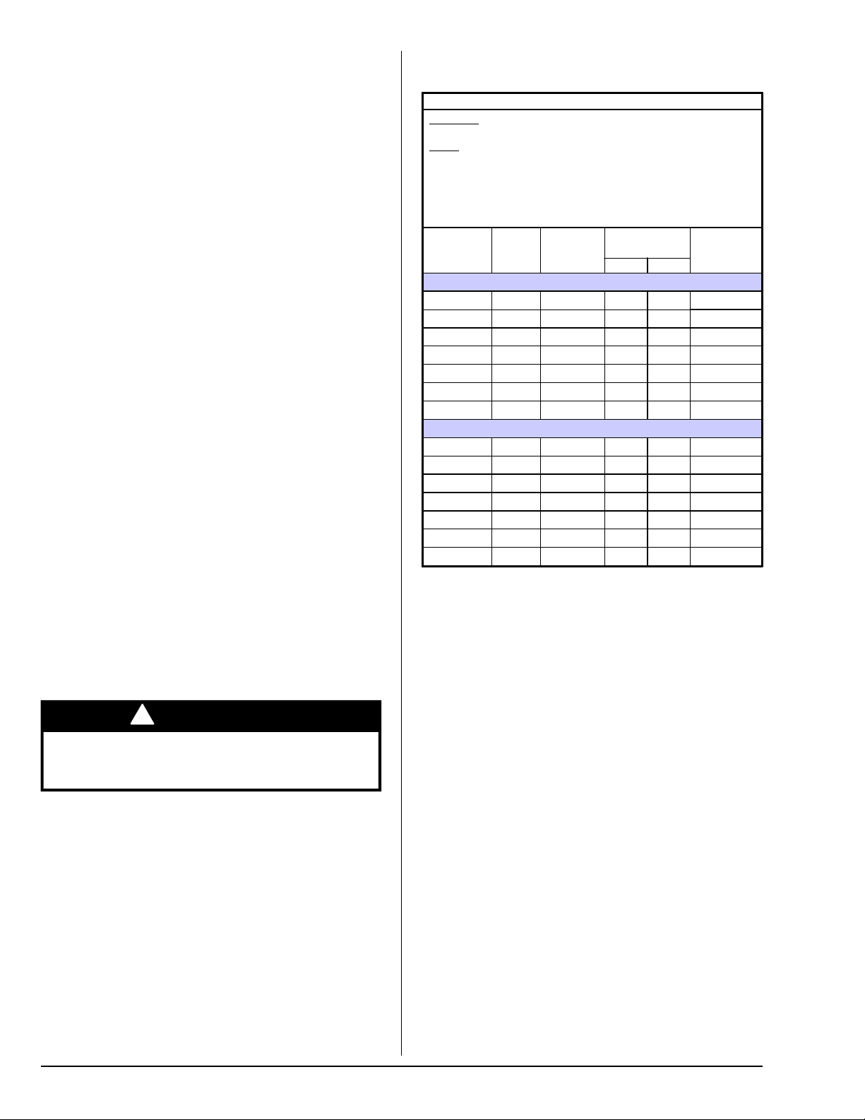
Air supply (make-up air) must be given careful consideration
to ensure proper performance of each dryer. Fresh air
ventilation openings shall not be blocked and/or sealed. As
a general rule, an unrestricted air entrance from the outdoors
of 144 inch2(929.03 cm2) is required. (Based on 1 inch2
[6.5 cm2] per 1,000 Btu [252 kcal].)
It is not necessary to have a separate make-up air opening
for each dryer. Common make-up air openings are acceptable.
However, they must be set up in such a manner that the
make-up air is distributed equally to all the dryers.
Exhaust Requirements _______________
IMPORTANT: Dryer should be located where a minimum
amount of exhaust duct will be necessary.
CAUTION: This dryer produces combustible lint and
must be exhausted to the outdoors. Every six months,
inspect the exhaust ducting and remove any lint
buildup.
Exhaust ductwork should be designed and installed by a
qualified professional. Improperly sized ductwork will create
excessive back pressure, which results in slow drying,
increased use of energy, overheating of the dryer, and
shutdown of the burner by the airflow (sail) switches, burner
hi-limits, or tumbler hi-limit thermostats. (Refer to the
illustrations on the following page for details.) The dryer must
be installed with a proper exhaust duct connection to the
outside.
The design of the flue system shall be such that any
condensate formed when operating the appliance from cold
shall either be retained and subsequently re-evaporated or
discharged.
CAUTION: This dryer produces combustible lint and
must be exhausted to the outdoors.
Improperly sized or installed exhaust ductwork can
create a potential fire hazard.
When possible, it is desirable to provide a separate exhaust
air duct for each dryer. The duct should go as directly as
possible to the outside air. Avoid sharp 90° right-angle turns
in ducting; use 30° or 45° angles instead. The radius of the
elbows should preferably be a minimum of 1-1/2 times the
diameter of the duct. To protect the outside end of the duct
from the weather, it may be bent downwards as indicated on
the following page. Leave at least twice the diameter of the
duct as clearance between the duct opening and the nearest
obstruction. If the exhaust duct goes through the roof, it may
be protected from the weather by using a 180° turn to point
the opening down. Allow at least twice the diameter of the
duct as clearance from the nearest obstruction.
Do not use screens, louvers, or caps on the outside opening
of the exhaust ductwork. The ducting should be smooth inside
with no projections from sheet metal screws or other
obstructions, which will collect lint. Additionally, inspection
doors should be installed at strategic points in the exhaust
ductwork for periodic inspection and cleaning.
Inadequate exhaust facilities may cause high temperature limit
switches or airflow switches to shut off the dryers. Do not
disable the switches, which are provided for your safety.
Instead, investigate the exhaust ducting. Any obstruction or
air friction due to numerous elbows/fittings in the ducting will
slow the passage of air through the system with resulting
inefficiency and potential fire hazard.
IMPORTANT: Exhaust back pressure measured by a
manometer at the dryer’s exhaust duct area must be no
less than 0 and must not exceed 0.6 in WC (1.48 mb).
NOTE: When the exhaust ductwork passes through a wall,
ceiling, or roof made of combustible materials, the opening
must be 2-inches (5.08 cm) larger than the duct (all the
way around). The duct must be centered within this
opening.
A = 12-inches (30.48 cm) B = 24-inches (60.96 cm)
EXAMPLE: For a bank of 4 dryers, 2 unrestricted openings
measuring 12-inches by 24-inches (30.48 cm by 60.96 cm)
are acceptable.
To compensate for the use of registers or louvers used over
the openings, this area must be increased by approximately
33%. Make-up air openings should not be located in an area
directly near where exhaust vents exit the building.
Allowances must be made for remote or constricting
passageways or where dryers are located at high altitudes or
predominantly low pressure areas.
IMPORTANT: Make-up air must be free of dry cleaning
solvent fumes. Make-up air that is contaminated by dry
cleaning solvent fumes will result in irreparable damage to
the motors and other dryer components.
NOTE: Component failure due to dry cleaning solvent
fumes will void the warranty.

113019-7www.adclaundry.com 9
If the length of the duct run or quantity of elbows used exceeds
the above noted specifications, the cross-sectional area of
the ductwork may need to be increased.
IMPORTANT: For extended ductwork runs, the cross
section area of the ductwork can only be increased to an
extent. When the ductwork approaches the maximum limits
noted in this manual, a professional HVAC firm should be
consulted for proper venting information.
Multiple Dryer (Common) Venting
If it is not feasible to provide separate exhaust ducts for each
dryer, ducts from individual dryers may be channeled into a
“common main duct.” The individual ducts should enter the
bottom or side of the main duct at an angle not more than 45°
in the direction of airflow. The main duct should be tapered,
with the diameter increasing before each individual 10-inch
(25.4 cm) duct (when dryer common exhaust is used) is added.
IMPORTANT: No more than four dryers or eight tumblers
total should be connected to one main common duct.
The main duct may be any shape provided that the minimum
cross-sectional area is maintained. The illustration below
shows the minimum cross-sectional area for multiple dryer
venting. These figures must be increased if the main duct run
from the last dryer to where it exhausts to the outdoors is
unusually long (over 30 feet [9.1 meters]) or has numerous
elbows (more than one) in it.
This calculation of 45 feet (13.7 meters) compensates or
allows for the use of a maximum of two elbows. Refer to the
illustration below.
IMPORTANT: The dryer exhaust duct must not be
connected to any gas vent, chimney, wall, ceiling, or
concealing space of a building.
It is recommended that exhaust or booster fans not be
used in the exhaust ductwork system.
As per the National Fuel Gas Code, “Exhaust ducts for
type 2 clothes dryers shall be constructed of sheet metal or
other noncombustible material. Such ducts shall be
equivalent in strength and corrosion resistance to ducts
made of galvanized sheet steel not less than 26 gauge
(0.0195-inches [0.50 mm]) thick.”
Single Dryer Venting (8” Duct)
IMPORTANT: A minimum exhaust duct size of 8-inches
(20.3 cm) must be used.
For an 8-inch (20.3 cm) run where a maximum of two elbows
are used (refer to the following illustration), the ductwork from
the dryer outlet must not exceed 10 feet (3.0 meters).
This calculation of 10 feet (3.0 meters) compensates or allows
for the use of a maximum of two elbows. Refer to the illustration
below.
If the length of the duct run or quantity of elbows used exceeds
the above noted specifications, the cross-sectional area of
the ductwork may need to be increased.
IMPORTANT: For extended ductwork runs, the cross
section area of the ductwork can only be increased to an
extent. When the ductwork approaches the maximum limits
noted in this manual, a professional HVAC firm should be
consulted for proper venting information.
Single Dryer Venting (10” Duct)
IMPORTANT: A minimum exhaust duct size of 10-inches
(25.4 cm) must be used for extended runs.
For a 10-inch (25.4 cm) run where a maximum of two elbows
are used (refer to the following illustration), the ductwork from
the dryer outlet must not exceed 45 feet (13.7 meters).

10 American Dryer Corp. 113019-7
Electrical Information ________________
Electrical Requirements
All electrical connections must be made by a properly licensed
and competent electrician. This is to ensure that the electrical
installation is adequate and conforms to local and state
regulations or codes. In the absence of such codes, all
electrical connections, materials, and workmanship must
conform to the applicable requirements of the National
Electrical Code ANSI/NFPA NO. 70-LATEST EDITION or in
Canada, the Canadian Electrical Codes Parts 1 & 2 CSA
C22.1-1990 or LATEST EDITION.
IMPORTANT: Failure to comply with these codes or
ordinances, and/or the requirements stipulated in this
manual can result in personal injury or component failure.
NOTE: Component failure due to improper installation will
void the warranty.
Each dryer should be connected to an independently protected
branch circuit (each pocket can be independently wired, if you
prefer). The dryer must be connected with copper wire only.
Do not use aluminum wire, which could cause a fire hazard.
The copper conductor wire/cable must be of proper ampacity
and insulation in accordance with electric codes for making
all service connections.
NOTE: The use of aluminum wire will void the warranty.
IMPORTANT: A separate protected circuit must be provided
to each dryer.
NOTE: An individual ground circuit must be provided to
each dryer, do not daisy chain.
IMPORTANT: The dryer must be connected to the electric
supply shown on the data label. In the case of 208 VAC or
240 VAC, the supply voltage must match the electric service
specifications of the data label exactly. The amp draw listed
on data plate is per pocket.
The wire size must be properly sized to handle the related
current.
!WARNING
208 VAC and 240 VAC are not the same. Any damage
done to dryer components due to improper voltage
connections will automatically void the warranty.
NOTE: Component failure due to improper voltage
application will void the warranty.
The manufacturer reserves the right to make changes in
specifications at any time without notice or obligation.
* Separate circuit for top and bottom pocket. 8/18/14
Grounding
A ground (earth) connection must be provided and installed in
accordance with state and local codes. In the absence of
these codes, grounding must conform to applicable
requirements of the National Electrical Code ANSI/NFPA NO.
70-LATEST EDITION, or in Canada, the installation must
conform to applicable Canada Standards: Canadian Electrical
Codes Parts 1 & 2 CSA C22.1-1990 or LATEST EDITION.
The ground connection may be to a proven earth ground at
the location service panel.
For added personal safety, when possible, it is suggested that
a separate ground wire (size per local codes) be connected
from the ground connection of the dryer to a grounded cold
water pipe. Do not ground to a gas pipe or hot water pipe.
The grounded cold water pipe must have metal-to-metal
connection all the way to the electrical ground. If there are
any nonmetallic interruptions, such as, a meter, pump, plastic,
rubber, or other insulating connectors, they must be jumped
out with a wire (size per local codes) and securely clamped to
bare metal at both ends.
IMPORTANT: For personal safety and proper operation, the
dryer must be grounded.
Provisions are made for ground connection in each dryer at
the electrical service connection area.
Electrical Service Specifications
Gas Models Only
ELECTRICAL SERVICE SPECIFICATIONS (PER DRYER)
IMPORTANT:
NOTES: A.
B.
C.
208 VAC AND 230/240 VAC ARE NOT THE SAME. When ordering,
specify exact voltage.
When fuses are used they must be dual element, time delay, current
limiting, class RK1 or RK5 ONLY. Calculate/determine correct fuse
value, by applying either local and/or National Electrical Codes to
listed appliance amp draw data.
Circuit breakers are thermal-magnetic (industrial) motor curve type
ONLY. For others, calculate/verify correct breaker size according to
appliance amp draw rating and type of breaker used.
Circuit breakers for 3-phase (3ø) dryers must be 3-pole type.
SERVICE
VOLTAGE PHASE WIRE
SERVICE
APPROX.
AMP DRAW CIRCUIT
BREAKER
60 Hz 50 Hz
NON-REVERSING
120 1ø 214.2 —20
120*1ø 27.1 —15 (2)
200 1ø 2—615
208 1ø 22.5 —15
220 1ø 25.1 4.6 15
230 1ø 24.8 1.95 15
240 1ø 24.8 —15
REVERSING
120 1ø 214.2 —20
120*1ø 27.1 —15 (2)
200 1ø 2—515
208 1ø 24.8 —15
220 1ø 25.1 4.6 15
230 1ø 24.8 4.55 15
240 1ø 24.8 —15

113019-7www.adclaundry.com 11
A ground wire is provided in the electrical box to connect your
service ground.
Gas Information ______________________
It is your responsibility to have all plumbing connections made
by a qualified professional to ensure that the gas plumbing
installation is adequate and conforms to local and state
regulations or codes. In the absence of such codes, all
plumbing connections, materials, and workmanship must
conform to the applicable requirements of the National Fuel
Gas Code ANSI Z223.1-LATEST EDITION, or in Canada, the
Canadian Installation Codes CAN/CGA-B149.1-M91 (Natural
Gas) or CAN/CGA-B149.2-M91 (L.P. Gas) or LATEST
EDITION.
In Australia, the fuel gas code is AS 5601/AG 601, local
authority, gas, electricity, and any other relevant statutory
regulations.
IMPORTANT: Failure to comply with these codes or
ordinances, and/or the requirements stipulated in this
manual, can result in personal injury and improper
operation of the dryer.
Each dryer must have its own manual shutoff valve to provide
isolation of the dryer from the gas supply.
The dryer and its individual shutoff valve must be disconnected
from the gas supply piping system during any pressure testing
of that system at test pressures in excess of 1/2 psig (3.5
kPa). The dryer must be isolated from the gas supply piping
system by closing its individual manual shutoff valve during
any pressure testing of the gas supply system at test pressures
equal to or less than 1/2 psig (3.5 kPa).
IMPORTANT: Failure to isolate or disconnect the dryer from
supply as noted can cause irreparable damage to the gas
valve voiding the warranty.
Type of Gas Manifold Pressure*In-Line Pressure
Natural 3.5 in wc 6.0 - 12.0 in wc
8.7 mb 14.92 - 29.9 mb
Liquid
Propane
10.5 in wc 11.0 in wc
26.1 mb 27.4 mb
Shaded areas are stated in metric equivalents
* Measured at outlet side of gas valve pressure tap when gas valve is on.
Gas Connections
Inlet connection ..................... 1/2” N.P.T. (1 per dryer)
Inlet supply size..................... 1/2” Pipe (minimum)
Btu/hr input (per pocket)........ 72,000 (18,143 kcal/hr)
Natural Gas
Regulation is controlled by the dryer’s gas valve’s internal
regulator. Incoming supply pressure must be consistent
between a minimum of 6.0 in WC (14.92 mb) and a maximum
of 12.0 in WC (29.9 mb) pressure.
Electrical Connections Leads
Black
+
Positive
White
-
Neutral
Green
Ground
(L1) (L2) (GND)
Electrical Connections
A wiring diagram is located inside the control box for connection
data.
If local codes permit, power to the dryer can be made by the
use of a flexible UL listed power cord/pigtail (wire size must
conform to rating of dryer), or the dryer can be hard wired
directly to the service breaker panel. In both cases, a strain
relief must be installed where the wiring enters the dryer.
Gas Models Only
IMPORTANT: A separate protected circuit must be provided
to each dryer.
Single-Phase (1ø)
Wiring Connections / Hookup
The electrical input connections on all single-phase (1ø) gas
dryers are made into the junction box located at the top left
side area of the dryer (refer to page 6).
!WARNING
Fire or explosion could result due to failure of isolating
or disconnecting gas supply as noted.
Gas Supply
The gas dryer installation must meet the American National
Standard...National Fuel Gas Code ANSI Z223.1-LATEST
EDITION, or in Canada, the Canadian Installation Codes CAN/
CGA-B149.1 M91 (Natural Gas) or CAN/CGA-B149.2-M91
(L.P. Gas) or LATEST EDITION, as well as local codes and
ordinances and must be done by a qualified professional.
NOTE: Undersized gas piping will result in ignition
problems, slow drying, increased use of energy, and can
create a safety hazard.
The dryer must be connected to the type of heat/gas indicated
on the dryer data label. If this information does not agree with
the type of gas available, do not operate the dryer. Contact
the reseller who sold the dryer or contact the manufacturer.
IMPORTANT: Any burner changes or conversions must be
made by a qualified professional.
The input ratings shown on the dryer data label are for
elevations up to 2,000 feet (610 meters), unless elevation
requirements of over 2,000 feet (610 meters) were specified
at the time the dryer order was placed with the factory. The
adjustment or conversion of dryers in the field for elevations
over 2,000 feet (610 meters) is made by changing each burner
orifice. If this conversion is necessary, contact the reseller
who sold the dryer or contact the manufacturer.
Technical Gas Data
Gas Specifications

12 American Dryer Corp. 113019-7
Shaded area is stated in metric equivalent
* D.M.S. equivalents are as follows:
Natural Gas ................#20 = 0.161” (4.089 mm).
L.P. Gas ......................#41 = 0.096” (2.438 mm).
Piping Connections
All components/materials must conform to National Fuel Gas
Code Specifications ANSI Z223.1-LATEST EDITION, or in
Canada, CAN/CGA-B149.1-M91 (Natural Gas) or CAN/CGA-
B149.2-M91 (L.P. Gas) or LATEST EDITION (for General
Installation and Gas Plumbing), as well as local codes and
ordinances and must be done by a qualified professional. It
is important that gas pressure regulators meet applicable
pressure requirements, and that gas meters be rated for the
total amount of all the appliance Btu being supplied.
The dryer is provided with one 1/2” N.P.T. inlet pipe connection
extending out the top left corner of the dryer (refer to page 6).
It is recommended that a gas shutoff valve be provided to the
gas supply line of each dryer for ease in servicing.
An 1/8” N.P.T. plugged tap, accessible for a test gauge
connection, must be installed in the main gas supply line
immediately upstream of each dryer.
IMPORTANT: Pipe joint compounds that resist the action of
natural gas and L.P. gas must be used.
Test all connections for leaks by brushing on a soapy water
solution (liquid detergent works well).
!WARNING
NEVER TEST FOR LEAKS WITH A FLAME!!!
The size of the main gas supply line (header) will vary
depending on the distance this line travels from the gas meter
or, in the case of L.P. gas, the supply tank, other gas-operated
appliances on the same line, etc. Specific information
regarding supply line size should be determined by the gas
supplier.
NOTE: Undersized gas supply piping can create a low or
inconsistent pressure, which will result in erratic operation
of the burner ignition system.
Preparation for Operation / Start-Up _
The following items should be checked before attempting to
operate the dryer:
Read all “caution,” “warning,” and “direction” labels attached
to the dryer.
Check incoming supply voltage to be sure that it is the same
as indicated on the dryer data label.
Gas Models – check to ensure that the dryer is connected to
the type of heat/gas indicated on the dryer data label.
The sail switch damper assembly was installed and adjusted
at the factory prior to shipping. However, each sail switch
adjustment must be checked to ensure that this important
safety control is functioning.
Check bolts, nuts, screws, terminals, and fittings for tightness.
Gas Models – be sure that all gas shutoff valves are in the
open position.
Be sure all back guard panels and service box covers have
been replaced.
Check the lint door to ensure that it is closed and secured in
place.
Rotate the tumbler by hand to be sure it moves freely.
TYPE OF GAS (PER POCKET)
Btu/hr
Rating
kcal/hr
Rating
Natural Liquid Propane
Qty. D.M.S.*Part No. Qty. D.M.S.*Part No.
72,000 18,143 1#20 140908 1#41 140909
Liquid Propane Conversion Kit Part Number 884439
L.P. Gas
Dryers made for use with L.P. gas have the gas valve’s internal
pressure regulator blocked open so that the gas pressure must
be regulated upstream of the dryer. The pressure measured
at each gas valve pressure tap must be a consistent 10.5 in
WC (26.1 mb). There is no regulator or regulation provided in
an L.P. dryer. The water column pressure must be regulated
at the source (L.P. tank) or an external regulator must be added
to each dryer.

113019-7www.adclaundry.com 13
Preoperational Test __________________
All dryers are thoroughly tested and inspected before leaving
the factory. However, a preoperational test should be
performed before the dryer is publicly used. It is possible that
adjustments have changed in transit or due to marginal location
(installation) conditions. Installer must instruct the user on
how to correctly operate the dryer before leaving.
Turn on electric power to the dryer.
Refer to the operating instructions for starting your particular
model dryer.
Gas Dryers
When a gas dryer is first started (during initial start-up), it has
a tendency not to ignite on the first ignition attempt. This is
because the gas supply piping is filled with air, so it may take
a few minutes for the air to be purged from the lines.
NOTE: During the purging period, check to be sure that all
gas shutoff valves are open.
Gas model dryers are equipped with an ignition system,
which has internal diagnostics. If ignition is not established
after one time, the heat circuit in the ignition module will
attempt two more ignitions (total of three ignition attempts).
If there is no flame after the third ignition attempt, the
module will lock out until it is manually reset. To reset the
ignition system, open and close the main door and restart
the dryer.
A burner gas pressure measurement should be taken at the
gas valve outlet pressure tap of each gas valve to ensure that
the water column pressure is correct and consistent.
NOTE: Water column burner pressure requirements
(measured at the outlet pressure tap of the gas valve body):
Natural Gas ........ 3.5 in WC (8.7 mb).
L.P. Gas .............. 10.5 in WC (26.1 mb).
IMPORTANT: There is no regulator provided in an L.P.
dryer. The water column pressure must be regulated at the
source (L.P. tank) or an external regulator must be added to
each dryer.
Make a complete operational check of all safety related circuits:
Door Switch(es)
Hi-Limit Thermostats
Cycling Thermostats
Sail Switch
Make a complete operational check of all operating controls.
NOTE: If computer program changes are required, refer to
the computer programming section of the manual supplied
with the dryer.
The dryer should be operated through one complete cycle to
ensure that no further adjustments are necessary and that all
components are functioning properly.
Tumbler Coating
The tumbler is treated with a protective coating. We suggest
dampening old garments or cloth material with a solution of
water and nonflammable mild detergent and tumbling them in
the tumbler to remove this coating.
Preoperational Instructions __________
Coin Models
Microprocessor Controller (Computer)
When the microprocessor controller (computer) is in the ready
state, the L.C.D. screen will display “FILL” followed by the
amount to start.
Insert coin(s). Once the correct “Amount to Start” has been
inserted, the L.C.D. will display “PUSH”.
Select temperature by pressing “HI,” “LO,” or “PERM PRESS.”
The cycle will start and the L.C.D. will display the Dry Cycle
selected and the remaining time.
The dryer will continue through the drying and cooling cycles,
until the vended time has expired.
NOTE: To stop the dryer, open the main door. Continuation
of the cycle will resume only after the door has been closed
and any of the three temperature selection buttons is
pressed.
Upon completion of the drying and cooling cycles, the tone
(buzzer) will sound and the dryer will go into the Anti-Wrinkle
Mode, if active, for up to 99 minutes, or until the main door or
lint drawer has been opened.
IMPORTANT: For more detailed information regarding the
microprocessor controller (computer) on your dryer, refer to
the microprocessor user’s manual included with the dryer.
Shutdown Instructions _______________
If the dryer is to be shutdown (taken out of service) for a period
of time, the following must be performed:
Discontinue power to the dryer either at the external disconnect
switch or the circuit breaker.
Discontinue the gas supply (for gas models only):
Shut off external gas supply shutoff valve.
Service / Parts Information __________
Service
Service must be performed by a qualified trained technician,
service agency, or gas supplier. If service is required, contact
the reseller from whom the equipment was purchased. If the
reseller cannot be contacted or is unknown, contact the Service
Department for a reseller in your area.
NOTE: When contacting the Service Department, be sure to
give them the correct model number and serial number so
that your inquiry is handled in an expeditious manner.
Parts
Replacement parts should be purchased from the reseller from
whom the equipment was purchased. If the reseller cannot
be contacted or is unknown, contact the Parts Department for
a reseller in your area. Parts may also be purchased directly
from the factory by calling the Parts Department at (508)
678-9000, FAX in your order at (508) 678-9447, or visit us
online at www.adclaundry.com.
NOTE: When ordering replacement parts from the reseller
or the manufacturer, be sure to give them the correct model
number and serial number so that your parts order can be
processed in an expeditious manner.

14 American Dryer Corp. 113019-7
IMPORTANT: No replacements, credits, or refunds will be
issued if the claim cannot be processed due to insufficient
information. The party filing the claim will be notified in
writing, either by “FAX” or “CERTIFIED MAIL – Return
Receipt Requested,” as to the information necessary to
process claim. If reply is not received by the Warranty
Department within 30 days from the FAX/letter date, then no
replacements, credits, or refunds will be issued, and the
merchandise will be discarded.
Routine Maintenance ________________
Cleaning
A program and/or schedule should be established for periodic
inspection, cleaning, and removal of lint from various areas of
the dryer, as well as throughout the ductwork system. The
frequency of cleaning can best be determined from experience
at each location. Maximum operating efficiency is dependent
upon proper air circulation. The accumulation of lint can restrict
this airflow. If the guidelines in this section are met, an ADC
dryer will provide many years of efficient, trouble free, and
most importantly, safe operation.
!WARNING
Lint from most fabrics is highly combustible. The
accumulation of lint can create a potential fire hazard.
Keep dryer area clear and free from combustible
materials, gasoline, and other flammable vapors and
liquids.
NOTE: Suggested time intervals shown are for average
usage, which is considered six to eight operational
(running) hours per day.
IMPORTANT: Dryers produce combustible lint and must be
exhausted to the outdoors. Every six months, inspect the
exhaust ducting and remove any lint buildup.
Suggested Cleaning Schedule
Every Third or Fourth Load
Clean the lint drawer screen every third or fourth load. A
clogged lint screen will cause poor dryer performance. Inspect
the lint screen and replace if torn.
NOTE: The frequency of cleaning the lint screen can best
be determined from experience at each location.
Weekly
Clean lint accumulation from the lint chamber, thermostat, and
microprocessor temperature sensor (sensor bracket) area.
!WARNING
To avoid the hazard of electrical shock, discontinue
electrical supply to the dryer.
90 Days
Remove lint from around tumbler, drive motor, and surrounding
areas.
Remove lint from the gas valve burner area with a dusting
brush or vacuum cleaner attachment.
Warranty Information ________________
Warranty Registration
Visit us at www.adclaundry.com and register all of your new
dryers by clicking on “Warranty” under the “Service” menu.
Warranty
For a copy of the commercial warranty covering your particular
dryer(s), contact the reseller from whom you purchased the
equipment and request a dryer warranty form. If the reseller
cannot be contacted or is unknown, warranty information can
be obtained from the factory by contacting the Warranty
Department at (508) 678-9000.
NOTE: Whenever contacting the factory for warranty
information, be sure to have the dryer’s model number and
serial number available so that your inquiry can be handled
in an expeditious manner.
Returning Warranty Parts
All dryer or parts warranty claims or inquiries should be
addressed to the Warranty Parts Department. To expedite
processing, the following procedures must be followed:
No parts are to be returned without prior written authorization
(R.M.A.) from the factory.
NOTE: An R.M.A. is valid for only 30 days from date of
issue.
The R.M.A. issued by the factory, as well as any other
correspondence pertaining to the returned part(s), must be
included inside the package with the failed component.
Each part must be tagged with the following information:
Model number and serial number of the dryer from which part
was removed.
Nature of failure (be specific).
Date of dryer installation.
Date of part failure.
Specify whether the part(s) being returned is for a replacement,
a credit, or a refund.
NOTE: If a part is marked for a credit or a refund, the
invoice number covering the purchase of the replacement
part must be provided.
Warranty tags (P/N 450064) are available at “no charge”
from ADC upon request.
The company returning the part(s) must clearly note the
complete company name and address on the outside of the
package.
All returns must be properly packaged to ensure that they are
not damaged in transit. Damage claims are the responsibility
of the shipper.
IMPORTANT: No replacements, credits, or refunds will be
issued for merchandise damaged in transit.
All returns should be shipped to the ADC factory in such a
manner that they are insured and a proof of delivery can be
obtained by the sender.
Shipping charges are not the responsibility of ADC. All returns
should be “prepaid” to the factory. Any “C.O.D.” or “COLLECT”
returns will not be accepted.

113019-7www.adclaundry.com 15
When contacting ADC, certain information is required to
ensure proper service/parts information from ADC. This
information is on the data label affixed to the right side panel
area at the rear of the dryer. When contacting ADC, please
have the model number and serial number available.
1. MODEL NUMBER – This describes the style of dryer and
type of heat (gas, electric, or steam).
2. SERIAL NUMBER – Allows the manufacturer to gather
information on your particular dryer.
3. TYPE OF HEAT– This describes the type of heat for your
particular dryer, gas (either natural gas or L.P. gas),
electric, or steam.
4. HEAT INPUT (For Gas Dryers) – This describes the heat
input in British thermal units per hour (Btu/hr) or kilowatts
(kW).
5. ORIFICE SIZE (For Gas Dryers) – Gives the number drill
size used.
6. ELECTRIC SERVICE – This describes the voltage and
current rating for a particular model.
7. GAS MANIFOLD PRESSURE (For Gas Dryers) – This
describes the manifold pressure taken at the gas valve
tap.
Procedure for Functional Check
of Replacement Components ________
DSI Module
Theory of Operation: Start the drying cycle. When the gas
burner ignites within the chosen trial for ignition time
(8-seconds), the flame sensor detects gas burner flame and
signals the DSI module to keep the gas valve open as long as
there is a call for heat. The DSI module will “LOCKOUT” if the
gas burner flame is not sensed at the end of the trial for ignition
period. The trial for ignition period will be repeated for a total
of three retries/trials (the initial try and two more retries/trials).
If the flame is not sensed at the end of the third retry/trial
(inter-purge period of 30-seconds), the DSI module will
“LOCKOUT” (a red L.E.D. diagnostic indicator will flash).
An unlit red L.E.D. diagnostic indicator indicates normal
operation.
A lit green L.E.D. diagnostic indicator indicates dryer controller
is calling for heat and that all interlocks have been satisfied.
Clean any lint accumulation in and around both the blower
and drive motor casing openings.
NOTE: To prevent damage, avoid cleaning and/or touching
ignitor/flame-probe assembly.
Every Six Months
Inspect and remove lint accumulation in customer furnished
exhaust ductwork system and from dryer’s internal exhaust
ducting.
NOTE: The accumulation of lint in the exhaust ductwork can
create a potential fire hazard.
Do not obstruct the flow of combustion and ventilation air.
Check customer furnished back draft dampers in the
exhaust ductwork. Inspect and remove any lint
accumulation, which can cause the damper to bind or stick.
A back draft damper that is sticking partially closed can
result in slow drying and shutdown of heat circuit safety
switches or thermostats.
If the hi-limit trips due to a high temperature occurrence,
you must disconnect power before resetting. To reset,
press and release the reset button, which is located in the
lint compartment of the dryer.
When cleaning the dryer cabinet(s), avoid using harsh
abrasives. A product intended for the cleaning of
appliances is recommended.
Adjustments
7 Days After Installation
and Every Six Months Thereafter
Inspect bolts, nuts, screws, setscrews, grounding connections,
and nonpermanent gas connections (unions, shutoff valves,
and orifices). Motor and drive belt should be examined.
Cracked or seriously frayed belt should be replaced. Tighten
loose belts when necessary. Complete operational check of
controls and main valves. Complete operational check of all
safety devices (door switch, lint drawer switch, sail switch,
burner and exhaust hi-limit thermostats).
Data Label Information _______________

16 American Dryer Corp. 113019-7
Non-Coin Programming _______________
To Enter Programming Mode
Press And Keys Together
To Exit Programming Mode Press Multiple Times
Until Display Returns to “Ready”.
0: SELECT LANGUAGE
1: SELECT SYSTEM PARAMETERS
0: DRYER SETUP
0: SELECT MODEL
1: SYSTEM TEMP
2: ENTER LINT COUNT 1 TO 5
3: ENTER AUDIO ALERT ON TIMES 0 TO 10
4: ROTATION SENSOR
1: REVERSING SETUP
0: ENTER SPIN TIME 30 TO 120 SECONDS
1: ENTER STOP TIME 5 TO 10 SECONDS
WRINKLE GUARD SETUP
2: 0: WRINKLE GUARD AUDIO ALERT
3: STEAM INJECTION SETUP
2: PROGRAM A - F CYCLES
ENTER A - F
SELECT CYCLE TYPE
AUTO
0: REVERSE MODE
1: ENTER DRY TEMP 160 (71) TO 200 F (94 C) *
2: ENTER DRYNESS LEVEL
3: ENTER CYCLE ADJUSTMENT VALUE 0 TO 99
4: CONTROLLED COOL DOWN
5: ENTER COOL DOWN TIME 0 TO 99 MINUTES
6: ENTER COOL DOWN TEMP 70 (21) TO 100 F (38 C)
MANUAL
0: REVERSE MODE
1: ENTER DRY TIME 0 TO 99 MINUTES
2: ENTER DRY TEMP 100 (38) TO 200 F (94 C) *
3: CONTROLLED COOL DOWN
4: ENTER COOL DOWN TIME 0 TO 99 MINUTES
5: ENTER COOL DOWN TEMP 70 (21) TO 100 F (38 C)
6: STEAM INJECTION
3: PROGRAM 0 - 40 CYCLES
ENTER 0 - 40
SELECT CYCLE TYPE
AUTO
0: REVERSE MODE
1: ENTER DRY TEMP 160 (71) TO 200 F (94 C) *
2: ENTER DRYNESS LEVEL
3: ENTER CYCLE ADJUSTMENT VALUE 0 TO 99
4: CONTROLLED COOL DOWN
5: ENTER COOL DOWN TIME 0 TO 99 MINUTES
6: ENTER COOL DOWN TEMP 70 (21) TO 100 F (38 C)
MANUAL
0: REVERSE MODE
1: ENTER DRY TIME 0 TO 99 MINUTES
2: ENTER DRY TEMP 100 (38) TO 200 F (94 C) *
3: CONTROLLED COOL DOWN
4: ENTER COOL DOWN TIME 0 TO 99 MINUTES
5: ENTER COOL DOWN TEMP 70 (21) TO 100 F (38 C)
6: STEAM INJECTION
4: DEFAULT SETTING FAULT HISTORY
5: SAFE SYSTEM VALVE TEST OR + A
DISPLAY: SAFE TEMP TUMBLER TEMP CTL VAC / RPM
* 160 F (71 C) MAXIMUM TEMP ON AXIAL MODELS
Phase 7.2 Non-Coin Diagnostic Codes
MAIN DOOR OPENED – A main door or door circuit is open.
EXHAUST HIGH TEMP FAULT – Tumbler is above 220° F
(104° C).
LINT ACCESS OPEN – Lint drawer or lint door circuit is open.
EXHAUST HIGH LIMIT FAULT – Temp. disk under tumbler is
open.
SAILSWITCH CLOSED FAULT – Sail switch is closed – should
be open at the start of a cycle.
O
O
O
SAIL SWITCH OPEN FAULT – Sail switch remained open after
the cycle started. Should have closed.
BURNER HIGH LIMIT FAULT – Burner temp. disk has opened.
BURNER IGNITION CONTROL – No signal to gas valve from
(DSI) module during trial for ignition time. DSI module is bad.
IGNITION FAULT – Gas valve did not remain open after trial
for ignition. Indicates that no flame was detected.
FLAME FAULT – Flame was detected during trial for ignition
but failed later.
ROTATION FAULT – Indicates the tumbler is not rotating.
OPEN EXHAUST TEMPERATURE PROBE – Indicates the
exhaust temperature probe is open or shorted.
OPEN FIRE SUPPRESSION SYSTEM (F.S.S.) PROBE FAULT
– Indicates the temperature probe for the F.S.S. is open or
shorted.
LOW VOLTAGE FAULT – Volt dropped below the operating
value.
EE PROM FAULT ### – Error in memory location. Fault
correction:
Enter the program mode by pressing the UP and STOP keys.
Press “4” and ENTER keys in password “FAA” Press UP
ARROW.
Press enter to confirm reset of EE PROM.
Inputs (Red L.E.D.s)
All indications are with L.E.D. lit
ESTOP – Indicates E-STOP has been pressed.
GAS_V – Indicates the gas valve is open (ON).
BRHL – Indicates the burner high limit disk is closed
(temperature below 330° F [166° C]).
SAIL – Indicates the sail switch is closed.
EXHL – Indicates the exhaust high limit disk is closed
(temperature below 225° F [107° C]).
MAIN – Indicates the status of main door is closed.
LINT – Indicates the lint drawer is closed.
FUSE – Indicates the status of the control voltage after
POWER ON button has been pressed.
Outputs (Green L.E.D.s)
All indications are with L.E.D. lit
AUX – This is for a spare output to be programmed.
STEAM – Indicates the status of the steam injection output.
_HEAT – Indicates the status of the heat output.
AIR – Indicates the status of the air jet output.
REV – Indicates the status of the tumbler reverse direction
output.
If the request to tumble the drum in the reverse direction is
made, then the L.E.D. is ON.
FWD – This L.E.D. will indicate the status of the tumbler forward
direction output.
FAN – This L.E.D. will indicate the status of the fan output.
O

113019-7www.adclaundry.com 17
Coin Programming ____________________
Enter Programming Mode By Placing
The Programming Switch On The Phase 7 Board Up
While No Cycle Is In Progress.
“Program Mode” Will Then Be Displayed.
Navigating Within The Programming Mode:
“Med” Key To Enter A Program Location.
“Hi-temp” / “Lo-temp” Keys Increase / Decrease
Program Location.
“Pause” Key Rejects Entry And Moves To Next
Program Location.
Changing A Parameter Value:
With Parameter Value Displayed Pressing “Lo Temp”
Or “High Temp” Changes The Parameter Value.
“Med” Key Must Be Pressed To Accept A New Parameter.
150F (66C) Maximum Temperature on Axial Models
Typical Programming Example:
Change a single coin acceptor from factory setting to yield 20
minutes for $.50, $.50 as the minimum amount to start, and
no differential in regard to temperature key selection.
Settings: Time for Amt to Start (PL03, PL04, PL05) 20
Left Coin Denomination (PL06) ............. $ .25
Amount to Start (PL06) .......................... $ .50
Clearing Coin Credit:
NO CYCLE IN PROGRESS AND PROGRAM SWITCH
DOWN.
Hold PAUSE while pressing HI 3 times, LO twice, and MED
once.
“Clear Credit?” will appear. Press any key to complete.
Accessing and Clearing Coin Vault Total
Enter program mode by switching program switch (up) while
no cycle is in progress.
Press HI – “Coin Vault total is $XXX” will appear.
Press HI – “Clear Coin Vault Total?” will appear.
Press MED to clear this amount or PAUSE to leave as is.
Hot Keys:
In the Coin Mode Hot Keys are enabled while in a cycle by
placing the program switch in the program (up) position.
In Free Mode Hot Keys are always enabled.
HI – Remaining credit – coin mode / remaining time – free
mode.
MED – Temps – Exhaust / left, S.A.F.E. / right, Axial / middle
(Axial dryer)
LO – Tumbler RPM
S.A.F.E. TEST: Switch to program mode. Press and hold the
“Pause” key until prompted to press MED to open the water.
L.C.D. Operating Messages
When Display Reads “Out of Order”
Pressing LO displays one of the causes listed below.
MODEL FAULT – Wrong model selected at PL01/3rd position.
SAIL SWITCH CLOSED – Sail switch closed before starting.
SAIL SWITCH OPEN – Sail switch failed to close after starting.
BURNER HI-LIMIT – Oven thermostat switch has opened.
EXHAUST HI-LIMIT – Tumbler thermostat switch has opened.
BURNER CONTROL – No gas valve signal – Bad DSI unit.
IGNITION FAULT – No flame ignition detected thru all retries.
FLAME FAULT – Flame detected at ignition but failed later.
CLEAN LINT – Due to failure to clean out lint.
CHECK CONTROL BOARD FUSE #2 – 2 on Phase 7 board
is open.
EXHAUST PROBE FAULT / AXIAL – Indicated probe has failed.
ROTATION SENSOR – Rotation sensor or tumbler drive has
failed.
EXHAUST HI-TEMP – Overheating condition has occurred.
BURNER PURGE FAULT – Gas return signal before heat
output.
“S.A.F.E. System Disabled”
In Coin Mode hold “Pause” and “LO” keys down together.
OPEN / SHORTED THERMISTOR – Probe or probe circuit
bad.
OPEN / SHORTED WATER VALVE – Water valve or circuit
bad.
WATER NOT CONNECTED – No water pressure at sol. valve.
“S.A.F.E. System (was) Activated”
Indicates the S.A.F.E. system is active or was active because
a fire was detected. The buzzer sounds at a fast pace while
the system is active.
FUNCTION SAMPLE AXIAL
DRYER SETTINGS
PL01
CONTROL
SETTINGS
Language English
Temperature Scale F
Buzzer Mode Buzz
Beep Count 1 to 9 Beeps 2
Dry Mode Coin Dry Mode
Pause Time 1 to 3 Minutes 1 Minute
Ready Prompt Rdy Inst Amt to Start
PL02
MACHINE
SETTINGS
Model Gas Dual Motors
Rotation Sensor On
Lint Clean 1 to 10 Hours 2
Axial Thermistor Input On
Axial Thermistor Setpoint 180F 82C
PL03
HI KEY
SETTINGS
Time for Amt to Start 1-99M 10 Minutes
Time for Top Off 1 to 99 M 10 Minutes
Dry Temp 100 to 190F* 150F 66C
Cool Time 0 to 9 Minutes 2
PL04
MED KEY
SETTINGS
Time for Amt to Start 1-99M 12 Minutes
Time for Top Off 1 to 99 M 12 Minutes
Dry Temp 100 to 190F* 140F 60C
Cool Time 0 to 9 Minutes 2
PL05
LO KEY
SETTINGS
Time for Amt to Start 1-99M 14 Minutes
Time for Top Off 1 to 99 M 14 Minutes
Dry Temp 100 to 190F* 120F 49C
Cool Time 0 to 9 Minutes 2
PL06
VENDING
ITEMS
Currency Symbol USD ($)
Vending Mode Accumulative Time
Vending Safeguard Bad Coin Reset
Left Coin Den .05 to 25.00 0.25
Right Coin Den .05 to 25.00 0.10
Amount to Start .05 to 25.00 0.25
Amount for Top Off 0.25
PL07 No Faults / Faults

ADC Part No. 1130197 - 08/20/14
Table of contents
Other ADC Dryer manuals
Popular Dryer manuals by other brands

Fagor
Fagor 3 SF-6 E operating instructions

Blomberg
Blomberg TKF 8451 SGC 30 manual

Kenmore
Kenmore 110-62612101 Installation guides

GE
GE Profile DPGT750 Owner's manual and installation instructions

Electrolux Professional
Electrolux Professional TE1120HP user manual

Bosch
Bosch WTY887W0EE Installation and operating instructions