International Biomedical AeroNOx 2.0 User manual

Portable Nitric Oxide
Titration & Monitoring System
Operator’s Manual
Aero ™
2.0
NOx
INT-ENG
P
h
F
a
E-
M
We
M
a
In
t
8
2
A
u
U
S
A
u
E
m
P
r
2
5
T
h
T
h
one:
(
5
1
a
x: (512)
M
ail: sa
l
e
bsite:
h
a
iling ad
d
t
ernation
2
06 Cros
s
u
stin, TX
S
A
u
thorize
d
m
ergo E
u
r
insesse
g
5
14 AP
h
e Hague
,
P
o
T
itrati
o
1
2) 873-0
0
873-909
0
l
es@int-
b
h
ttp://ww
w
d
ress:
al Biom
e
s
Park D
r.
78754
d
represe
n
u
rope
g
racht 20
,
The Ne
t
o
rtabl
o
n &
M
Oper
0
33
0
b
io.com
w
.int-bio
.
e
dica
l
r.
n
tative i
n
t
herland
s
e Nitr
M
onit
o
ator’s
M
.
com
n
Europe
s
r
ic Ox
i
o
ring
S
M
anual
for Reg
u
i
de
S
yste
u
latory A
f
m
f
fairs:

This page intentionally left blank.

TABLE OF CONTENTS
Part No. 715-0006, Rev. F - 1 -
1.GENERAL INFORMATION ......................................................................................................... 3
1.1.Introduction ..................................................................................................................... 3
1.2.Intended Use ................................................................................................................... 3
1.3.Medical Indication ........................................................................................................... 3
1.4.Contraindication ............................................................................................................. 3
1.5.Safety Summary .............................................................................................................. 4
1.6.Classification .................................................................................................................. 4
1.7.Important Safety Considerations ................................................................................... 4
1.8.Symbols ......................................................................................................................... 10
1.9.Abbreviations ................................................................................................................ 1 2
1.10.Unpacking ..................................................................................................................... 13
1.11.Initial Setup ................................................................................................................... 13
1.12.Purge Procedure ........................................................................................................... 14
1.13.Front Panel .................................................................................................................... 15
1.14.Rear Panel ..................................................................................................................... 16
1.15.Navigating Display Screens ......................................................................................... 17
1.16.Universal Power Supply ............................................................................................... 19
1.17.Theory of Operation ...................................................................................................... 20
1.18.Environmental Effects .................................................................................................. 22
2.PRE-USE CHECKOUT/ALARM VERIFICATION ..................................................................... 24
3.PATIENT OPERATIONS ........................................................................................................... 37
3.1.Before Operation........................................................................................................... 37
3.2.Connection to Ventilator Circuit (General) ................................................................. 37
3.3.INOstat Bagger backup NO Delivery System ............................................................. 37
3.4.INOstat Kit Pre-Use Checkout ..................................................................................... 38
3.5.INOstat Kit Instructions for Use................................................................................... 41
3.6.Connection to Various Breathing Systems ................................................................ 42
3.7.Connection DIAGRAM - ICU Ventilator Circuit ........................................................... 43
3.8.Connection DIAGRAM - Transport Ventilator Circuit ................................................ 45
3.9.Connection Diagram - High Frequency TXP-2D Phasitron ....................................... 47
3.10.Connection Diagram - AeroNOx 2.0 Bagger ............................................................ 48
4.ALARMS ................................................................................................................................... 49
4.1.General Alarm Information ........................................................................................... 49
4.2.Priority Alarms .............................................................................................................. 4 9
4.3.Alarm Silencing ............................................................................................................. 49
4.4.User Adjustable Monitor Alarms ................................................................................. 50
4.5.Safety Shut Off .............................................................................................................. 5 1
4.6.Alarm Table ................................................................................................................... 52
5.CALCULATIONS & TROUBLESHOOTING ............................................................................. 54
5.1.Calculations for Nitric Oxide Delivery ......................................................................... 54
5.2.Gas Supply .................................................................................................................... 57

TABLE OF CONTENTS
Part No. 715-0006, Rev. F - 2 -
5.3.Troubleshooting Guide ................................................................................................ 58
6.CALIBRATION .......................................................................................................................... 65
6.1.Low Range (ZERO) Calibration (Daily) ........................................................................ 65
6.2.O2 High Range Calibration (WEEKLY) ........................................................................ 66
6.3.NO High Range Calibration (WEEKLY) ....................................................................... 68
6.4.NO2 High Range Calibration (WEEKLY) ...................................................................... 70
7.MAINTENANCE ........................................................................................................................ 73
7.1.User Maintenance Schedule ........................................................................................ 73
7.2.Cleaning the AeroNOx 2.0 ......................................................................................... 73
7.3.Preventive Maintenance ............................................................................................... 74
7.4.Return Merchandise Authorization ............................................................................. 74
7.5.Replacing NO, NO2, and O2 Sensors ........................................................................... 75
7.6.Battery Replacement .................................................................................................... 78
7.7.Replacing the Tip on the AeroNOx 2.0 Delivery Regulators .................................. 79
7.8.Parts and Accessories ................................................................................................. 80
7.9.Mounting Options ......................................................................................................... 80
7.10.Disposal ......................................................................................................................... 81
8.WARRANTY .............................................................................................................................. 8 2
9.PRODUCT SPECIFICATIONS .................................................................................................. 84
9.1.Ventilator Compatibility ................................................................................................ 84
9.2.Measurement Range and Accuracy ............................................................................ 84
9.3.Backup Delivery Regulator .......................................................................................... 84
9.4.INOstat Bagger .............................................................................................................. 84
9.5.AeroNOx 2.0 Delivery Regulator ............................................................................... 85
9.6.AeroNOx 2.0 Physical Specifications ....................................................................... 85
9.7.AeroNOx 2.0 Environmental Specifications ............................................................ 85
9.8.AeroNOx 2.0 Electrical Specifications ..................................................................... 86
9.9.Sensor Specifications .................................................................................................. 86
9.10.EMC Compliance ........................................................................................................... 86
9.11.Essential Performance ................................................................................................. 89
10.APPENDIX ................................................................................................................................ 90
10.1.NO2 Sensor Datasheet .................................................................................................. 90
10.2.NO Sensor Datasheet ................................................................................................... 92
10.3.Oxygen Sensor Datasheet ........................................................................................... 94
10.4.Competency Based Performance Check-off Tool ...................................................... 95

Part No. 715-0006, Rev. F - 3 -
1. GENERAL INFORMATION
1.1. Introduction
This manual describes the theory of operation, frequently used features, safety
considerations, specifications, and maintenance for the AeroNOx 2.0 nitric oxide (NO)
delivery system. Each AeroNOx 2.0 provides the basic equipment required for NO
delivery and accessories are available to accommodate specific installations.
The AeroNOx 2.0 system includes an integrated nitric oxide gas delivery system and
nitric oxide (NO), nitrogen dioxide (NO2), and oxygen (O2) analyzer. The AeroNOx 2.0
is a stand-alone, lightweight, portable unit designed to continuously monitor NO, NO2,
and O2 concentrations in a breathing circuit.
The AeroNOx 2.0 system is specifically designed for the delivery and monitoring of
gaseous nitric oxide (NO) in parts per million (ppm) concentrations.
The AeroNOx 2.0 is designed for use within a hospital or during patient transfer via
rescue vehicle, fixed wing aircraft, or helicopter.
1.2. Intended Use
The AeroNOx 2.0 is intended to provide a constant controlled concentration of nitric
oxide in breathing gas by delivering a constant controlled flow of nitric oxide into the
inspiratory limb of a mechanical ventilator that operates using a continuous constant flow
of fresh gas into the inspiratory limb of the ventilator. The AeroNOx 2.0 is also
intended to be used with a flow inflating manual ventilator (an AeroNOx 2.0 accessory),
by introducing controlled flows of nitric oxide into the fresh gas flow to the manual
ventilator. It is also intended to monitor nitric oxide, nitrogen dioxide, and oxygen
concentrations in the breathing gas.
The AeroNOx 2.0 is intended to be used within a hospital or during air or ground
transport outside the hospital.
1.3. Medical Indication
Nitric oxide therapy is intended to treat late pre-term neonates ( 34 weeks gestation,
< 14 days of age) diagnosed with Persistent Pulmonary Hypertension of the Newborn
(PPHN) described as:
a. A failure to achieve transition to air breathing due to a lung parenchymal disease
such as meconium aspiration syndrome, pneumonia, or infant respiratory distress
b. Idiopathic PPHN in which the lung parenchyma is normal but the pulmonary
vasculature has been remodeled
c. Documentation of pulmonary hypertension by a pediatric cardiologist
1.4. Contraindication
The only contraindication for inhaled nitric oxide therapy is neonates dependent on right-
to-left shunting of blood. Always refer to the inhaled Nitric Oxide Gas prescribing
information sheet.

Pa
r
T
h
to
g
U
s
s
h
D
o
If
a
U
s
r
t No. 715-00
0
1.5.
1.6.
1.7.
NOTE
S
h
e principal
g
ether her
e
s
e of the A
e
h
unt, conge
o
not use t
h
a
n alarm o
c
s
e only ph
a
0
6, Rev. F
Safety Su
m
The Aero
N
a qualified
with oper
a
A
eroNOx
2
putting int
o
removed f
r
Classifica
t
A
ccording
Medical e
l
is classifie
Cla
sh
o
IP3
soli
Co
n
Important
Safety co
n
cautions,
a
S
:
WARNIN
G
e
for emph
a
e
roNOx 2.
0
nital anom
a
h
e AeroNO
x
c
curs, safe
g
a
rmaceutic
a
m
mary
N
Ox 2.0 i
s
physician.
a
ting instru
c
2
.0 shoul
d
o
operation
r
om servic
e
t
ion
to the sta
n
l
ectrical eq
u
d as follow
ss II / Inter
n
o
ck
3, accordi
n
d objects
n
tinuous o
p
Safety Co
n
n
cerns or a
d
a
nd notes,
G
and CAU
a
sis.
0
is contr
a
a
lies, or co
n
x
2.0 in o
x
g
uard pati
e
a
l grade N
O
s
intended
f
A
ll perso
n
c
tions, war
n
d
be verifi
e
. If the uni
t
e
and repai
n
dard EN6
0
u
ipment, P
a
s:
n
ally Powe
n
g to the d
e
p
e
r
ation for
n
sideration
s
d
ditional p
e
having the
TION notic
a
indicated f
o
n
gestive h
e
x
ygen rich
e
nt before t
r
O
.
- 4 -
f
or use onl
y
n
nel operat
i
n
ings, and
c
e
d accordin
g
t
fails any
p
red.
0
601-1 of t
h
a
rt 1: Gene
r
ed, accor
d
e
gree of pr
o
the mode
o
s
e
rtinent inf
o
following s
A
a
A
d
es to be o
b
o
r patients
e
art failure.
environme
n
r
oubleshoo
y
by qualifi
e
i
ng the sys
t
c
autions c
o
g
to the pr
o
p
ortion of t
h
h
e Internati
o
e
ral require
m
d
ing to the
t
o
tection ag
a
o
f operatio
n
o
rmation wi
ignificance
A
lerts to
p
adverse e
v
A
lerts to th
damage to
Provides a
a point in t
h
b
served in
u
with cong
e
nts.
o
ting or rep
a
e
d clinician
t
em shoul
d
o
ntained in
o
cedures i
n
h
e checkou
o
nal Electr
o
m
ents for s
t
ype of p
r
o
t
a
inst harmf
u
n
ll be displa
y
:
p
otential s
e
v
ent, or s
a
e possibilit
y
the equip
m
dditional in
h
e manual.
u
se of this
d
e
nital heart
a
ir procedu
s, under th
e
d
be thorou
g
this manu
a
n
this manu
a
t procedur
e
o
technical
C
afety, the
A
t
ection aga
ul ingress
o
y
ed using
w
e
rious inj
u
a
fety haza
r
y
of minor i
m
ent.
formation t
o
d
evice are
disease o
n
res.
e direction
g
hly famili
a
a
l. The
a
l before
e
, it must b
e
C
ommissio
A
eroNOx 2.
inst electri
c
o
f water an
d
w
arnings,
u
ry,
r
d.
i
njury or
o clarify
brought
n
right-to-le
f
of
r
e
n,
0
c
d
f
t

Part No. 715-0006, Rev. F - 5 -
The AeroNOx 2.0 must be used in accordance with indications, usage, contraindications, warnings,
and cautions described in this manual.
The use of devices which radiate high intensity electrical fields may affect the operation of the
AeroNOx 2.0. Constant assessment of the patient and all life support equipment is mandatory
whenever interfering devices are operating on or near patient.
When using the AeroNOx 2.0 adjacent to or stacked with other equipment, observe the operation of
the AeroNOx 2.0 and the other equipment to ensure normal operation.
Portable RF communications equipment (including peripherals such as antenna cables and external
antennas) should be used no closer than 30 cm to any part of the AeroNOx 2.0 and associated
cables. Otherwise, degradation of the performance of this equipment could occur.
Do not use the AeroNOx 2.0 with helium/oxygen mixtures. The AeroNOx 2.0 is only intended to
deliver NO in conjunction with oxygen/air mixtures.
Anytime a new NO gas cylinder and regulator is used, the user must purge to prevent inadvertent
delivery of NO2 to the patient.
If the AeroNOx 2.0 is not going to be used within 10 minutes, depressurize the regulator supply line.
If the AeroNOx 2.0 is pressurized and not used within 10 minutes, repeat the purge procedure.
If the AeroNOx 2.0 is not depressurized and not used within 12 hours, repeat the pre-use procedure.
A backup NO delivery system must always be available in the event the primary system should fail.
Set AeroNOx 2.0 alarm thresholds for the current patient conditions to monitor any inadvertent
changes in treatment. For alarm information, see Section 4., ALARMS.
Be certain all lines and cables are organized to prevent damage or occlusion.
Use only parts, accessories, transducers, and cables designated by International Biomedical for use
with the AeroNOx 2.0. Cables and accessories other than those supplied by International
Biomedical may result in unacceptable operation of the AeroNOx 2.0 and will void the equipment
warranty.
The AeroNOx 2.0 samples gas at a rate of 220 mL/min; this can affect the sensitivity of flow triggered
synchronized breath of some ventilators. The trigger sensitivity, if equipped, should be checked after
connecting AeroNOx 2.0 to the breathing circuit.
Do not change NO, NO2, or O2 sensors while in use.
Do not attempt to maintain, diagnose, or repair the AeroNOx 2.0 while delivering NO to a patient.
No modification of the AeroNOx 2.0 is allowed.
Improper sensor or battery replacement will result in a non-functional or inaccurate device.
Sample/Delivery accessories are single patient use only. DO NOT re-use.
Pa
r
I
m
s
h
P
e
e
x
m
e
O
v
to
T
h
s
e
C
a
or
a
p
W
n
o
s
e
C
o
p
a
b
e
W
d
e
IN
D
o
T
h
D
o
e
x
D
o
b
e
T
h
e
n
T
h
T
h
IN
T
h
u
s
r
t No. 715-00
0
m
proper ma
i
h
ould be pe
e
rform cyli
n
x
posure to
n
e
dical gas
c
v
erexposur
the operat
o
h
e IP33 rati
e
aled.
a
ution: U.
S
other licen
p
plicable re
s
hen using
t
o
t actively
b
e
conds bef
o
o
ncentratio
n
a
tients to N
O
e
flushed fo
hen using
t
e
livered ga
s
Ostat Bag
g
o
not use
A
h
e generati
o
o
not alter t
x
cessive le
v
o
not subst
i
e
en design
e
h
e
A
eroNO
x
n
dotracheal
h
e
A
eroNO
x
h
e INOstat
Ostat Kit i
s
h
e back-up
s
ed only wi
t
0
6, Rev. F
i
ntenance
o
rformed by
n
der conne
c
n
itric oxide
c
ylinders.
e to NO or
o
r.
ng applies
S
. Federal
a
sed medic
a
s
trictions.
t
he
A
eroN
O
b
agging pat
o
re and aft
e
n
s of NO
2
i
O
2
in the r
e
r 20 secon
d
t
he
A
eroN
O
s
concentr
a
g
er are des
A
eroNOx 2.
0
o
n of NO
2
i
he length
o
v
els of NO
2
i
tute
A
ero
N
e
d and test
e
x
2.0 Ba
g
tube. Do
n
x
2.0 Ba
g
K
it is inten
d
s
not intend
delivery re
g
t
h the INO
s
o
r replace
m
qualified s
c
tion and p
u
or nitrogen
NO
2
can l
e
when the
A
a
nd Canad
a
l practitio
n
O
x 2.0 Ba
ient, turn
N
e
r use to c
o
n the reser
v
e
servoir ba
g
d
s.
O
x 2.0 Ba
a
tion includi
igned for s
h
0
Bagger
ncreases r
a
o
f the INOs
t
.
N
Ox 2.0 B
e
d for pati
e
g
ger and IN
n
ot insert
a
g
ger and IN
d
ed for use
ed as a pri
m
g
ulator in t
h
s
tat Bagger
.
m
ent of sen
s
ervice pe
r
s
u
rge proce
d
dioxide g
a
e
ad to phys
i
A
eroNOx 2.
ian law re
s
n
er. Outsid
gger or IN
O
N
O flow off
t
o
mpletely r
e
v
oir bag m
a
g
. If any in
t
gger or IN
O
ng NO
2
is
p
h
ort term u
s
or INOstat
a
pidly abo
v
t
at Bagger
agger or I
N
e
nt safety
w
Ostat Bag
g
a
ny additio
n
Ostat Bag
g
if the prim
a
m
ary NO d
e
h
e INOstat
.
Do not u
s
- 6 -
s
ors may p
s
onnel per
t
d
ures in w
e
a
s. Follow
y
i
ological ef
f
0 is on b
a
s
tricts this d
e Canada
a
O
stat Bagg
e
t
o prevent
f
e
move NO
a
a
y exceed
t
erruption
o
O
stat Bagg
e
p
ossible.
T
s
e only.
Bagger to
v
e this con
c
gas suppl
y
N
Ostat Bag
g
w
ith the co
m
g
er are inte
n
al tubing b
g
er are sin
g
a
ry NO del
i
e
livery dev
Kit is pres
e
s
e this reg
u
p
ose a safe
t
t
he instruct
e
ll-ventilate
y
our facilit
y
f
ects such
a
a
ttery pow
e
d
evice to s
a
a
nd the U.
e
r, oxygen
f
ormation
o
and NO
2
.
1 ppm. La
r
o
ccurs duri
n
e
r, short d
u
T
herefore, t
deliver co
n
c
entration.
y
tubing as
t
g
er compo
n
m
ponents i
n
nded to co
n
etween th
e
g
le patient
u
ivery devic
e
ice.
e
t with a 0.
2
u
lator for a
n
t
y risk to th
ions.
d areas to
y
’s safety p
r
a
s hypoxia
e
r with the
D
a
le by or on
S., check
w
and NO m
o
f NO
2
. Flu
s
rge tidal v
o
n
g patient
b
u
ration, rap
he
A
eroN
O
n
centration
t
his may c
a
n
ents. Th
e
n
cluded.
n
nect dire
c
e
Bagger a
n
u
se. Do n
o
e
(AeroNO
x
2
5 L/min fl
o
n
y other ap
p
e patient.
M
prevent in
a
r
ocedures
f
which are
D
C Input j
a
the order
o
w
ith local l
a
ix in the re
s
sh the bag
g
o
lumes ma
y
b
agging, s
y
id fluctuati
o
O
x 2.0 Ba
g
in excess
o
a
use gener
a
e
Bagge
r
S
y
c
tly to the p
a
n
d the end
o
o
t reproces
s
x
2.0) fail
o
w. It is int
e
p
lication.
M
aintenan
c
a
dvertent
f
or handlin
g
not appare
a
ck properl
y
o
f a physic
i
a
ws for
s
ervoir bag
g
e
r
for 20
y
expose
y
stem shou
l
o
ns in
g
ger and
o
f 20 ppm.
a
tion of
y
stems ha
v
a
tient’s
o
tracheal t
u
s
.
s. The
e
nded to b
e
c
e
g
nt
y
an
. If
l
d
v
e
u
be.
e

Part No. 715-0006, Rev. F - 7 -
Persons using the AeroNOx 2.0 should be trained and experienced in the use of this device to
assure effective administration of NO, and to avoid injury to the patient or to others resulting from
inhalation of excess NO, NO2, or other reaction products. Not for use by patients.
Persons using this device who may be particularly sensitive to nitric oxide or nitrogen dioxide, or who
may be exposed to these gases for prolonged periods as a result of the use of this device, should be
aware that the AeroNOx 2.0 does not scavenge the exhaust gas, and that this gas is vented from the
underside of the AeroNOx 2.0, or through the side vent in the event that the bottom port is occluded.
Ambient concentrations of nitric oxide or nitrogen dioxide expected to result from the use of this device
are less than 50 ppb.
Only use International Biomedical approved batteries for AeroNOx 2.0.
Even when the external power supply is not connected, the battery provides a bias charge to the NO,
NO2, and O2 cells to keep sensors in a ready state. The power drawn from biasing the sensors will
deplete a new fully charged battery in approximately one week. Because of this, it is recommended
the external power supply of the AeroNOx 2.0 remain plugged in at all times to maintain battery
charge.
Allowing the battery voltage to drop below the minimum discharge voltage can permanently damage
the battery. Even when the AeroNOx 2.0 is powered off, the battery can be over-discharged if the
battery is left connected and the external power supply is not plugged in. The power drawn from
biasing the sensors can drain the battery below the minimum discharge voltage.
Disconnect the battery or leave charging when not in use for extended periods of time.
Allowing the battery to fully discharge repeatedly will reduce the overall number of cycles in the life of
the battery.
Attempting to run the AeroNOx 2.0 for longer than five hours on battery only could result in an
interruption of nitric oxide therapy.
The specified power supply is defined as part of the ME Equipment. Use only the International
Biomedical approved universal power supply for AeroNOx 2.0.
No other devices are known to cause potential interference with the AeroNOx 2.0. If interference
occurs, discontinue use of the AeroNOx 2.0 and use the INOstat Bagger.
Never turn on the NO delivery gas without first turning on the ventilator or bagger flow. Failure to do
this will result in undiluted gas delivery entering the sampling chamber and exposing the sensors to
levels of NO and /or NO2 which may damage the sensors.
NO2 gas may have collected in the AeroNOx 2.0 delivery or ventilator circuit during setup. Run
ventilator and AeroNOx 2.0 on a test lung 30 seconds prior to patient connection to ensure analyzed
levels of NO2 and NO are appropriate.
Only use the NO Worries Sample line with filter and Nafion tubing when operating the AeroNOx 2.0.
Failure to do so may result in the egress of moisture which can impair function as well as damage
internal components.
NO flow must be continually evaluated during nitric oxide administration to ensure accurate dosing.

Part No. 715-0006, Rev. F - 8 -
NO cannot be administered during the calibration process.
Do not sterilize or disinfect with power connected.
Allow unit to dry thoroughly before use. Immediate use after exposure to excessive cleaning agents
such as Isopropyl Alcohol can affect sensor performance.
Do not push on LCD display.
The VESA 75 mount is required for mounting during transport.
Should there be a sudden need to change therapy tanks; a second tank should always be purged and
ready for immediate use. Perform the purge procedure immediately upon installation of a new
regulator.
The flush procedure must be performed each time NO therapy is started. This includes initial therapy
starts, tank changes, and re-starting therapy after NO has been off.
Powering the unit off will shut off the delivery gas flow. Gas flow is terminated when the unit is
powered off, whether intentionally, or during a complete loss of power.
DO NOT exceed 2.00 LPM as displayed on the AeroNOx 2.0 flow display. Displayed values in
excess of 2.00 LPM are not accurate. If the flow on the AeroNOx 2.0 flow meter is set at a value
greater than 2.00 LPM, the delivered flow will be higher than the displayed flow value.
The NO2 sensor may easily be damaged by inadvertent high levels of NO2. Use Nitrogen or air to
flush the system after high levels of NO (> 100 ppm) or NO2 (> 20 ppm) have been introduced to the
sensor.
Setting alarm limits to extreme values can render the alarm system useless.
After storage at the extremes of the allowable temperature range, it is recommended that the AeroNOx
2.0 be given at least an hour at room temperature before use.
NOTES:
The Low Cal does not require calibration gases.
Connections to various ventilators are unique to each manufacturer as well as their corresponding
disposable circuits.
When AeroNOx 2.0
is connected to a ventilator and patient is breathing spontaneously, a slight
change in NO ppm (< 10%) may be noted.
When performing high range calibration, make sure to select the correct calibration gas and confirm
expiration date before using.
Never connect calibration circuit to a pressure source > 50 cm H2O; this could damage the sampling
system.

Part No. 715-0006, Rev. F - 9 -
Protective cover not shown in many images throughout this manual should be used at all times to
provide extra impact resistance if dropped.
AeroNOx 2.0
is shipped with battery installed but disconnected. Follow connection procedure in
Section 7.
Do not mount or position the AeroNOx 2.0
such that the rear power connection, exhaust ports, or the
NO inlet are blocked.
The recommended storage temperature limits are within operational temperature limits to preserve
sensor life. No specific time to cool or warm from storage temperature extremes is indicated. Before
normal use, a pre-check must be performed to allow sensors to stabilize.
Use the tethered rubber plug to seal the DC input jack from the environment when not in use.
Pa
r
B
r
t No. 715-00
0
1.8.
(Blue
B
ackgroun
d
0
6, Rev. F
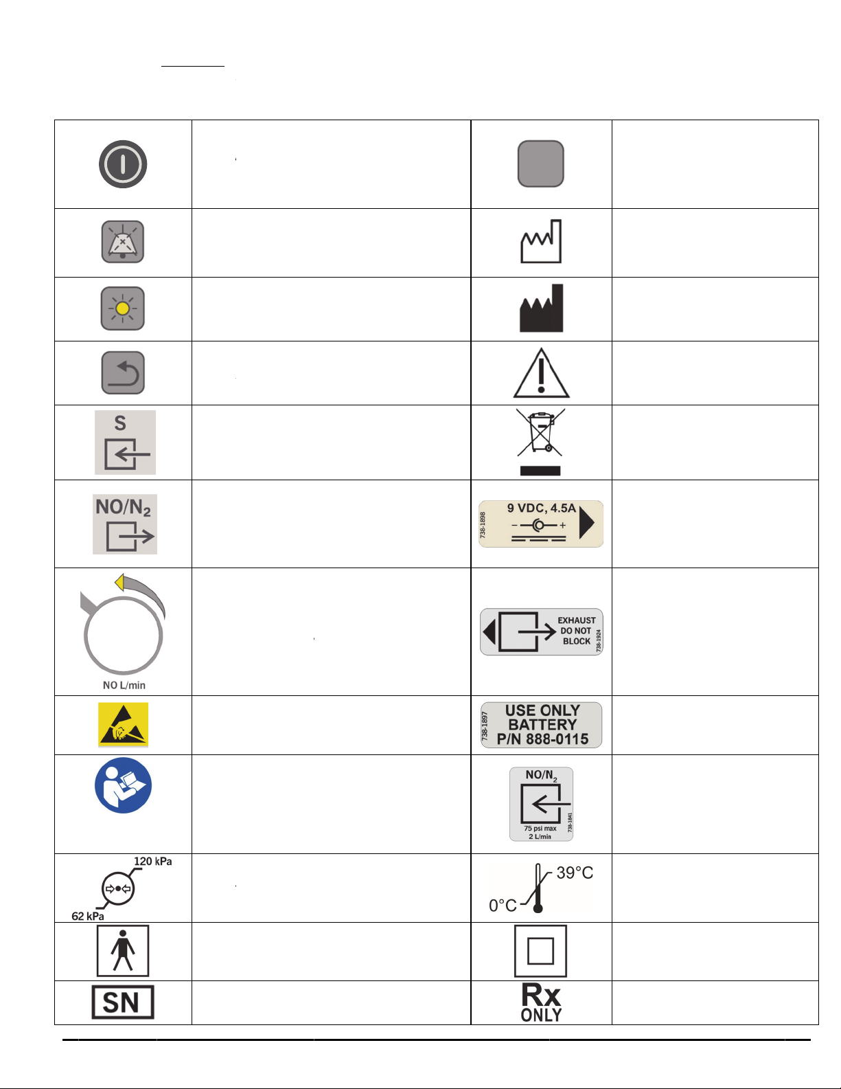
Symbols
The follo
w
“ON”
/
Sec
o
Silen
Dim
B
Bac
k
NO
S
NO/
N
Nitri
c
(Incr
e
A
TT
E
for h
a
devi
c
d
)
Con
s
Ope
r
w
ing symbol
/
”OFF” Po
w
o
nds to turn
ce Alarm
B
B
acklight
B
k
Button
S
ample Inl
e
N
2
Delivery
c
Oxide Flo
w
e
asing flo
w
E
NTION:
O
a
ndling ele
c
c
es.
s
ult Instruct
r
ating pres
s
Type B
F
Device
s
s appear i
n
w
e
r
(Hold f
o
off)
B
utton
B
utton
e
t
Outlet
w
Control
w
counter cl
o
bserve pre
c
trostatic s
e
ions For U
s
s
ure limits
F
Applied P
a
s
erial num
b
- 10 -
n
the Aero
N
o
r ~3
o
ckwise)
cautions
e
nsitive
s
e
a
rt
b
e
r
N
Ox 2.0 d
d
ocumentat
S
D
M
i
n
G
C
D
U
s
E
U
r
e
N
O
li
ion and la
b
S
oft Key (3)
D
ate of Ma
n
M
anufactur
e
n
formation
G
eneral W
a
C
aution, Ri
s
D
o not disc
a
U
se indicat
e
upply only
E
xhaust Do
U
se only th
e
e
placemen
t
N
O/N
2
Sup
p
O
perating t
e
mits
Class II
Prescript
i
b
els.
n
ufacture
e
r contact
a
rning,
s
k of Dang
e
a
rd in trash
e
d power
Not Block
e
specified
t
battery.
p
ly Gas Inp
e
mperatur
e
Equipment
i
on use onl
y
er
u
t
y

Pa
r
r
t No. 715-00
0
0
6, Rev. F
S
A
l
a
A
H
o
Nitri
c
Nitr
o
Se
t
Device
Con
elect High/
Incre
a
a
rm Temp
o
A
pproxima
t
Batt
e
F
u
o
ld Button
T
C
c
Oxide C
o
Pe
r
o
gen Dioxi
d
Parts
t
NO=0, N
O
Soft Key
part numb
e
firmation
Low Alarm
a
se Value
o
rarily Sile
n
t
ely 60 Se
c
e
ry Level
ll / Low
T
imer (Mo
v
C
hart)
o
ncentratio
n
r
Million
d
e Concen
t
Per Million
O
2
=0, and
%
(Hold to z
e
- 11 -
er
Limits
n
ced for
c
onds
v
ing Pie
n
in Parts
t
ration in
%
O
2
=21
e
ro)
A
Decre
a
Set Low
A
Set High
A
C Power
P
Ch
a
Scre
e
Screen U
n
un
Lock Pro
unacknow
l
Perce
n
Zero Calib
r
So
f
High Calib
r
So
f
a
se Value
A
larm Limi
t
Alarm Limi
P
lugged in
a
a
rging
e
n Lock
n
lock (Hold
lock)
hibited wit
h
l
edged ala
r
n
t Oxygen
r
ation Scre
e
f
t Key
r
ation Scre
e
f
t Key
t
t
a
nd
to
h
r
m
e
n
e
n

Part No. 715-0006, Rev. F - 12 -
1.9. Abbreviations
ABBREVIATION DEFINITION
AC Alternating Current
CISPR International Special Committee on Radio Interference
cm Centimeters
DC Direct Current
ESD Electrostatic Discharge
FiO2 Fraction of Inspired Oxygen
FSO Full Scale Output
ft. Feet
HFOV High Frequency Oscillatory Ventilation
IB International Biomedical
in Inches
L/min Liters per Minute
mA Milliamps
mbar Millibars
mL/min Milliliters per Minute
mm Millimeters
mmHg Millimeters of Mercury
N2 Nitrogen Gas
NO Nitric Oxide Gas
NO2 Nitrogen Dioxide Gas
O2 Oxygen Gas
PM Preventative Maintenance
ppb Parts per Billion
ppm Parts per Million
psi Pounds per Square Inch
psig Pounds per Square Inch Gauge
PTFE Polytetrafluoroethylene
RH Relative Humidity
RF Radio Frequency
V Volts
VESA Video Electronics Standards Association

Part No. 715-0006, Rev. F - 13 -
1.10. Unpacking
Verify that the shipping carton contains the following equipment.
Component Part Number Quantity
AeroNOx 2.0 731-9159 1
AeroNOx 2.0 NO supply Hose, 6’ 738-1862 1
AeroNOx 2.0 Multilanguage Documentation CD 717-0001 1
AeroNOx 2.0 Operator’s Manual 715-0006 1
Delivery Regulator with CGA 626 Fitting 731-9142 2
Power Supply Assembly, 9 V, AeroNOx 2.0 293-0011 1
Power Cord, NEMA 1-15P to IEC60320 C7, 6ft 738-1916 1
AeroNOx 2.0 Service Manual 715-0007 1
AeroNOx 2.0 Sample/Delivery Kit 738-1853 1
AeroNOx 2.0 TXP HFV Sample/Delivery Kit 738-1854 1
AeroNOx 2.0 Test Circuit 738-1889 1
AeroNOx 2.0 Calibration Circuit* 738-1850 1
*Calibration requires a calibration regulator. An INOstat Backup Bagger kit is also required in
the event of AeroNOx 2.0 failure during use. If your hospital does not have each of these,
they must be purchased as separate items shown below. The same regulator may be used
for NO and NO2, but a purge procedure must be completed each time it is attached to a new
bottle of gas.
Component Part Number Quantity
Calibration Regulator with CGA 625 Fitting 731-9141 1
INOstat Kit 731-9147 1
1.11. Initial Setup
a. Unpack the AeroNOx 2.0 and inspect for damage.
b. Install battery as per Section 7., MAINTENANCE, “Battery Replacement”. The
AeroNOx 2.0 was shipped with a disconnected battery for safety.
c. Unpack 9 VDC power supply (P/N 293-0011) and Power Cord (P/N 738-1916).
Plug in AeroNOx 2.0 and charge for ~72 hrs.
d. Calibrate the AeroNOx 2.0. (See Section 6., CALIBRATION.)
e. Perform Section 2., PRE-USE CHECKOUT/ALARM VERIFICATION, before
administering therapy to a patient.
f. Install AeroNOx 2.0 per the appropriate situation described in Section 3.,
PATIENT OPERATIONS.

Part No. 715-0006, Rev. F - 14 -
1.12. Purge Procedure
Please follow purge instructions below to ensure gas purity. Failure to follow these
instructions may introduce potentially harmful contaminants into the patient’s breathing
gas or may affect the monitoring analyzer’s accuracy by introduction of contaminants into
the calibration gas.
Any time a regulator is installed on a tank or cylinder of compressed gas, certain
precautions must be followed. This is to prevent contamination of the gas in the tank and
in the system by air that is trapped in the dead space of the regulator, hose, and fittings.
To eliminate the possibility of the oxygen in this air reacting with the nitric oxide to form
nitrogen dioxide in the system, the regulator, hose, and fittings must be purged before
use. The valve on the tank must not be opened and left open until the regulator is
purged. The stainless steel hose must also be purged prior to connection to the
AeroNOx 2.0.
1.12.1. Purge Procedures for use with Medical Gas Regulators:
a. Connect cylinder to a matching CGA 626 nitric oxide or nitrogen dioxide
regulator only.
b. Connect stainless steel hose to quick disconnect.
c. Open, then immediately close the cylinder valve pressurizing the hose.
d. Purge (bleed) all of the gas from the regulator and hose with the purge
pin on the AeroNOx 2.0.
e. Repeat steps c. and d. four more times for a total of five purge cycles.
f. Leave the regulator installed until it is time to change to a new cylinder.
g. Repeat the purge procedure any time a regulator is reattached.
Although the dead space volume in the regulator and hose assembly is physically small,
if it had been exposed to room air for a period of time it will contain sufficient oxygen to
convert a significant amount of nitric oxide to nitrogen dioxide.

Pa
r
r
t No. 715-00
0
1.13.
1
2
3
4
5
6
7
8
9
10
11
0
6, Rev. F
Front Pan
e
Sam
p
Delive
r
NO F
P
Ma
i
A
larm
B
a
S
o
Charg
Prote
e
l
p
le Line Inl
e
r
y Line Out
l
low Contro
P
owe
r
i
n Screen
Silence K
e
a
cklight
Back
o
ft Keys
ing Indicat
o
ctive Cove
r
e
t
S
l
et
l
e
y
Va
r
or
r
- 15 -
S
ample Lin
e
Set
s
Displays
Sile
Di
m
R
iable Func
t
Green L
Re
e
Filter Plu
g
Delivery
s
NO Flow
t
Turns P
o
Measured
nces Alar
m
m
s Backlig
h
eturns to p
t
ion Keys
C
L
ED illumin
a
e
movable i
m
g
s Into Qui
c
Line Fittin
g
t
o Delivery
o
wer On/Of
f
and Alarm
m
For One
M
h
t to 50% N
revious sc
r
C
orrespond
a
tes when
p
m
pact prot
e
c
k Discon
n
g
Outlet
f
Paramete
r
M
inute
ormal
r
een
to Screen
p
lugged-in
e
ction
n
ect
r
s
Menu

Pa
r
r
t No. 715-00
0
1.14.
1
2
3
4
5
6
7
8
9
10
0
6, Rev. F
Rear Pan
e
Se
n
Sam
p
Dov
e
Ba
t
Powe
r
Pow
e
VESA 7
5
e
l
NO/N
2
Ga
s
Purge
P
n
sor Housi
n
p
le Gas Ex
h
e
tail Mounti
n
t
tery Housi
n
r
Supply L
E
e
r Supply
C
5
Mount (4
Handl
e
s
Inlet
P
in
n
g Cove
r
h
aust Ports
n
g Bracket
n
g Cove
r
E
D Indicato
C
ord Outlet
M4 Scre
w
e
- 16 -
Q
Mo
u
r
Indi
c
Po
w
w
s)
Q
uick Con
n
Purge Pi
n
Houses N
O
Gas Es
c
u
nts Aero
N
Hou
c
ates if Uni
t
wer Suppl
y
75 mm
7
In
t
n
ect for N
O
n for NO D
O
, NO
2
, an
d
c
ape for Int
e
N
Ox 2.0 o
ses 6 volt
B
t
is Conne
c
y
Connecti
o
7
5 mm Mou
t
egrated H
a
O
Gas Deliv
e
elivery Lin
e
d
O
2
Sens
o
e
rnal Pum
p
n Pole or
H
B
attery
c
ted to A/C
o
n w/Dust
C
u
nting Patt
e
a
ndle
e
ry
e
o
rs
p
H
andle
Power
C
ove
r
e
rn

Pa
r
r
t No. 715-00
0
1.15.
0
6, Rev. F
Navigatin
g
There are
Main displ
1.15.1. M
O
1
2
3
4
5
6
7
8
g
Display S
c
two scree
n
ay screen
a
ain Displa
n the main
c
reens
n
s that can
a
nd Calibr
a
y Screen
screen th
e
B
- 17 -
be display
e
a
tion scree
n
e
operator
c
Upper
A
Lower
A
Measu
r
NO Flow
R
B
attery Life
A
larm
Mess
a
Screen
L
e
d on the
A
n
.
c
an monito
r
A
larm Limit
A
larm Limit
r
ed Value
R
ate Displ
a
or A/C Po
w
Settings
a
ge Area
L
ock Statu
s
A
eroNOx 2.
0
r
values an
d
a
y
w
e
r
s
0
NO del
i
d
alarm m
e
i
very syste
m
e
ssages.
m
.
Table of contents
Popular Measuring Instrument manuals by other brands


JNE
JNE BOR-ON instruction manual

P3 International
P3 International P4490 Kill A Watt Edge Operation manual

MKS
MKS 146C instruction manual

Tractel
Tractel dynafor HHD Installation, operating and maintenance manual

Stanley
Stanley TLM99 user manual

PCB Piezotronics
PCB Piezotronics J353B01 Installation and operating manual


