Intertek A/GPD1424 Series User manual

Goodman Manufacturing Company, L.P.
5151 San Felipe, Suite 500, Houston, TX 77056
www.goodmanmfg.com or www.amana-hac.com
©2011-2018 Goodman Manufacturing Company, L.P.
IO-407K
07/2018
Affix this manual and Users Information Manual
adjacent to the unit.
*NOTE: Please contact your distributor or our website for
the applicable Specification Sheet referred to in this manual.
I
NSTALLATION
I
NSTRUCTIONS
A/GPD 14 SEER “M” SERIES - S
INGLE
P
ACKAGE
D
UAL
F
UEL
G
AS
-E
LECTRIC
H
EATING
&C
OOLING
U
NITS
ATTENTION INSTALLING PERSONNEL
Prior to installation, thoroughly familiarize yourself with this
Installation Manual. Observe all safety warnings. During installa-
tion or repair, caution is to be observed.
It is your responsibility to install the product safely and to edu-
cate the customer on its safe use.
RECOGNIZE THIS SYMBOL
AS A SAFETY PRECAUTION.
These installation instructions cover the outdoor installation
of single package gas electric heating and cooling units. See
the Specification Sheet applicable to your model* for
information regarding accessories.
*NOTE: Please contact your distributor or our website for
the applicable Specifications Sheets referred to in this manual.
This ForcedAir Central Unit Design Complies With Requirements
Embodied in The American National Standard / National
Standard of Canada Shown Below.
ANSI Z21.47•CSA-2.3 Central Furnaces
O
NLY
PERSONNEL
THAT
HAVE
BEEN
TRAINED
TO
INSTALL
,
ADJUST
,
SERVICE
OR
REPAIR
(
HEREINAFTER
, “
SERVICE
”)
THE
EQUIPMENT
SPECIFIED
IN
THIS
MANUAL
SHOULD
SERVICE
THE
EQUIPMENT
. T
HE
MANUFACTURER
WILL
NOT
BE
RESPONSIBLE
FOR
ANY
INJURY
OR
PROPERTY
DAMAGE
ARISING
FROM
IMPROPER
SERVICE
OR
SERVICE
PROCEDURES
. I
F
YOU
SERVICE
THIS
UNIT
,
YOU
ASSUME
RESPONSIBILITY
FOR
ANY
INJURY
OR
PROPERTY
DAMAGE
WHICH
MAY
RESULT
. I
N
ADDITION
,
IN
JURISDICTIONS
THAT
REQUIRE
ONE
OR
MORE
LICENSES
TO
SERVICE
THE
EQUIPMENT
SPECIFIED
IN
THIS
MANUAL
,
ONLY
LICENSED
PERSONNEL
SHOULD
SERVICE
THE
EQUIPMENT
. I
MPROPER
INSTALLATION
,
ADJUSTMENT
,
SERVICING
OR
REPAIR
OF
THE
EQUIPMENT
SPECIFIED
IN
THIS
MANUAL
,
OR
ATTEMPTING
TO
INSTALL
,
ADJUST
,
SERVICE
OR
REPAIR
THE
EQUIPMENT
SPECIFIED
IN
THIS
MANUAL
WITHOUT
PROPER
TRAINING
MAY
RESULT
IN
PRODUCT
DAMAGE
,
PROPERTY
DAMAGE
,
PERSONAL
INJURY
OR
DEATH
.
is a registered trademark of Maytag Corporation or its related companies and is used under license. All rights reserved.
WARNING
Cancer and Reproductive Harm-
www.P65Warnings.ca.gov.

2
TO THE INSTALLER
Before installing this unit, please read this manual to familiarize yourself on the specific items which must be adhered to,
including maximum external static pressure to unit, air temperature rise, minimum or maximum CFM and motor speed connections.
IMPORTANT NOTE: If a crankcase heater is used, the unit should be energized 24 hours prior to compressor start up to ensure
crankcase heater has sufficiently warmed the compressor. Compressor damage may occur if this step is not followed.
TO THE OWNER
A warranty certificate is provided with the unit. Read the warranty carefully and note what is covered. Keep the warranty
certificate in a safe place so you can find it when necessary.
SHIPPING INSPECTION
Upon receiving the unit, inspect it for damage from shipment. Claims for damage, either shipping or concealed, should be filed
immediately with the shipping company. Check the unit model number, specifications, electrical characteristics and accessories to
determine if they are correct. In the event an incorrect unit is shipped, it must be returned to the supplier and must NOT be
installed. The manufacturer assumes no responsibility for installation of incorrectly shipped units.
SAFETY INSTRUCTIONS
The following symbols and labels are used throughout this manual to indicate immediate or potential safety hazards. It is the
owner’s and installer’s responsibility to read and comply with all safety information and instructions accompanying these symbols.
Failure to heed safety information increases the risk of personal injury, property damage, and/or product damage.
INDEX
TO THE INSTALLER ..................................................... 2
TO THE OWNER ......................................................... 2
SHIPPING INSPECTION ................................................. 2
SAFETY INSTRUCTIONS ................................................ 2
ORDERING PARTS ....................................................... 5
CODES AND REGULATIONS ............................................. 5
EPA REGULATIONS ...................................................... 5
NATIONAL CODES ....................................................... 5
PRE-INSTALLATION CHECKS ........................................... 6
UNIT INSTALLATION .................................................... 6
ALL INSTALLATIONS .............................................. 6
GROUND LEVEL INSTALLATIONS ONLY .............................. 6
ROOFTOP INSTALLATIONS ONLY .................................... 7
ROOF CURB INSTALLATIONS ONLY ................................. 7
GENERAL INFORMATION ............................................... 7
RIGGING DETAILS ........................................................ 8
GAS PIPING .............................................................. 8
HIGH ALTITUDE DERATE (U.S. INSTALLATIONS ONLY) .............. 8
PIPING ......................................................... 8
WIRING .....................................................11
HIGH VOLTAGE WIRING .......................................11
THERMOSTAT CONTROLS ........................................11
LOW VOLTAGE WIRING ........................................11
INTERNAL WIRING ..............................................11
CIRCULATING AIR AND FILTERS .....................................12
AIRFLOW CONVERSION .........................................12
HORIZONTAL AIR FLOW .........................................12
DUCTWORK ....................................................12
FILTERS .......................................................13
VENTING ..............................................................13
INSTALLATION - FLUE HOOD EXHAUST.............................13
INSTALLATION - COMBUSTION AIR INTAKE HOOD ....................13
CONDENSATE DRAIN ...................................................14
CONDENSATE DRAIN CONNECTION.................................14
NORMAL SEQUENCES OF OPERATION ..............................14
HEAT PUMP OPERATION ..............................................14
OUTDOOR THERMOSTAT .........................................14
OPTIONAL OUTDOOR THERMOSTAT (OTDFPKG-01) .............14
HEATING CYCLE (HEAT PUMP) ..................................14
HEATING CYCLE (NATURAL GAS/ LP)...........................14
DEFROST CYCLE ...............................................15
COOLING ......................................................15
FAN ONLY ....................................................15
AIR FLOW MEASUREMENT AND ADJUSTMENT .......................15
AIR FLOW ADJUSTMENTS FOR INDOOR BLOWER MOTOR ............15
START-UP, ADJUSTMENTS, AND CHECKS ............................16
HEATING START-UP ( NATURAL GAS / LP) ......................16
COOLING START-UP .............................................19
MAINTENANCE..........................................................19
FILTER REPLACEMENT OR CLEANING ...............................19
CABINET FINISH MAINTENANCE ..................................19
CLEAN OUTSIDE COIL (QUALIFIED SERVICER ONLY)...............19
CONDENSER, EVAPORATOR, AND INDUCED DRAFT MOTORS .........19
FLAME SENSOR (QUALIFIED SERVICER ONLY) ......................19
MAIN BURNER FLAME (QUALIFIED SERVICER ONLY) ...............20
APPENDIX ..............................................................21
TROUBLESHOOTING...................................................22
IGNITION CONTROL DIAGNOSTIC INDICATOR CHART .................23
HEATING TIMING CHART ........................................23
COOLING/HEAT PUMP TIMING CHART .............................23
UNIT DIMENSIONS ..............................................24
WIRING DIAGRAM ......................................................25
MINIMUM CLEARANCES ..........................................27
RECOMMENDED FILTER SIZES .....................................27
BLOWER PERFORMANCE DATA ....................................29
START-UP CHECKLIST ..................................................32
INDEX(continued)
3
FIREOR EXPLOSION HAZARD
Failure to follow the safety warnings exactly could result in
serious injury, death or property damage. Never test for
gas leaks with anopen flame. Use a commercially available
soap solution made specificallyfor thedetection of leaks
to check all connections. A fire or explosion may result
causing property damage, personal injury or
loss of life.
AVERTISSEMENT
RISQUE D'INCENDIE OU D'EXPLOSION
Si les consignes de sécuriténe sont pas suivies àla
lettre, cela peutentraîner la mort,de graves blessures
ou des dommages matériels. Ne jamais vérifier la
présence de fuites de gaz au moyen d'une flamme nue.
Vérifier tous les raccords en utilisant une solution
savonneuse commerciale conçue spécialement pour la
détection de fuites. Un incendie ou une explosion
risque de se produire, ce qui
peut entraîner la mort,
des blessures ou des dommages matériels.

4
AVERTISSEMENT
RISQUE D'INTOXICATION AU MONOXYDE DE
CARBONE
Si
appareil
raccordé au système de ventilation fonctionne
correctement au moyen des essais décrits ci-
dessus, les portes, les fenêtres, les ventilateurs, les
registres de foyer et tous les autres appareils de
combustion alimentés au gaz doivent être remis
dans leur état initial.
les étapes décrites ci-dessous ne sont pas
suivies pour chacun des appareils raccordés au système
de ventilation au moment de sa mise en marche, cela
peut entraîner une intoxicationau monoxyde de
carbone ou la mort. Lesétapes suivantes doivent être
suivies pour chacun des appareils raccordés au système
de ventilation au moment de sa mise en marche, alors
que tous les autres appareils raccordésau système de
ventilation ne sont pas en marche :
1) Sceller toutes les ouverturesinutilisées du système de
ventilation.
2) Inspecter le système de ventilation afin de vérifier si
la taille et l'inclinaison par rapport àl'horizontale sont
conformes aux exigences du National Fuel Gas Code,
ANSI Z223.1/NFPA 54 ou du Code d'installation du gaz
naturel et du propane, CSA B149.1 et à ces instructions.
Vérifier qu'il n'y a pas d'obstruction ou de restriction, de
fuite, de corrosion et d'autres problèmes qui pourraient
entraîner une situation dangereuse.
3) Si possible, fermer toutes les portes et fenêtres du
bâtiment ainsi quetoutes les portes séparant l'endroit
où se trouvent les appareils raccordés au système de
ventilationet les autres zones du bâtiment.
4) Fermer le registre des foyers.
5) Mettre les sécheuses en marche ainsi que tous les
autres appareils qui ne sont pas raccordés au système
de ventilation. Mettreen marche tous les ventilateurs
de tirage, comme celui des hottes de cuisine et des
salles de bains, et les régler à lapuissance maximale.Ne
pas mettre en marche les ventilateurs d'été.
6) Suivre les instructions d'allumage. Mettre en marche
l'appareil soumis à l'inspection.Régler le thermostat de
manière à ce que l'appareil fonctionne en continu.
7) Vérifier la présence de fuite au niveau de l'ouverture
du coupe-tiragedes appareils qui en sont dotés après 5
minutes de fonctionnement du brûleur principal. Utiliser
la flamme d'une allumette ou d'une bougie.
8) Si un problème de ventilation est observé pendant
l'un desessais décrits ci-dessus, des correctifs doivent
être apportés ausystème de ventilation conformément
au National Fuel Gas Code, ANSI Z223.1/NFPA 54 et (ou)
au Code d'installation du gaz naturel et du propane, CSA
B149.1.
9) Une fois qu'il a été déterminé que chaque
CARBON MONOXIDE POISONING HAZARD
Failure to follow the steps outlined below for each
appliance connected to the venting system being
placed into operation could result in carbon monoxide
poisoning or death.
The following steps shall be followed for each appliance
connected to the venting systembeing placed into
operation, while all other appliances connected to the
venting system are not in operation:
1) Seal any unused openings inthe venting system.
2) Inspect the venting systemfor proper size and
horizontal pitch, asrequired inthe National Fuel Gas
Code, ANSI Z223.1/NFPA 54 orthe Natural Gas and
Propane Installation Code, CSA B149.1 and these
instructions. Determine that there is no blockage or
restriction, leakage, corrosion and other deficiencies
which could cause an unsafe condition.
3) As far as practical, close all building doors and
windows and all doors between the space in which the
appliance(s) connected to the venting system are
located and other spaces of the building.
4) Close fireplace dampers.
5) Turn on clothes dryers and any appliance not
connected to the venting system. Turn on any exhaust
fans, such as range hoods and bathroom exhausts, so
they are operating at maximum speed. Do not operate
a summer exhaust fan.
6) Follow the lighting instructions. Place the appliance
beinginspected into operation.Adjust the thermostat
so appliance isoperating continuously.
7) Test forspillage from draft hood equipped
appliances at the draft hood relief opening after 5
minutes of main burner operation. Use the flame of a
match or candle.
8) If improper venting is observed during any of the
above tests, the venting system must be corrected in
accordance with the National Fuel Gas Code, ANSI
Z223.1/NFPA 54 and/or Natural Gas and Propane
Installation Code, CSA B149.1.
9) After it has been determined that each appliance
connected to the venting system properly vents when
tested as outlined above, return doors, windows,
exhaust fans, fireplace dampers and any other gas-fired
burning appliance to their previous conditions of use.

5
ORDERING PARTS
When reporting shortages or damages, or ordering repair parts,
give the complete model and serial numbers as stamped on the
units nameplate. Replacement parts for this appliance are available through your contractor or local distributor. For the location of
your nearest distributor, consult the white business pages, the yellow page section of the local telephone book or contact:
HOMEOWNER SUPPORT
GOODMAN MANUFACTURING COMPANY, L.P.
19001 KERMIER ROAD
HOUSTON, TEXAS 77484
877-254-4729
CODES AND REGULATIONS
The *PD M-series dual fuel units are designed for OUTDOOR USE ONLY. The *PD is only available in 2 through 4 ton and heating
capacities from 70,000 - 115,000 btu. The units can be easily installed in manufactured or modular homes with existing high-static
duct work. The units can also be easily converted to accommodate a plenum for normal or low-static applications. The *PD M-series
are self contained packaged units so the only connections needed for installation are the supply and return ducts, the line and low
voltage wiring drain connection and appropriate gas piping. Rated performance is achieved after 72 hours of operation. Rated
performance is delivered at the specified airflow. See outdoor unit specification sheet for split system models or product
specification sheet for packaged and light commercial models. Specification sheets can be found at www.goodmanmfg.com for
Goodman®brand products or www.amana-hac.com for Amana®brand products. Within either website, please select the residential
or commercial products menu and then select the submenu for the type of product to be installed, such as air conditioners or
heat pumps, to access a list of product pages that each contain links to that model’s specification sheet.
EPA REGULATIONS
IMPORTANT: THE UNITED STATES ENVIRONMENTAL PROTECTION AGENCY (EPA) HAS ISSUED VARIOUS REGULATIONS REGARDING THE INTRODUCTION AND
DISPOSAL OF REFRIGERANTS IN THIS UNIT. FAILURE TO FOLLOW THESE REGULATIONS MAY HARM THE ENVIRONMENT AND CAN LEAD TO THE IMPOSITION OF
SUBSTANTIAL FINES. BECAUSE REGULATIONS MAY VARY DUE TO PASSAGE OF NEW LAWS, WE SUGGEST ACERTIFIED TECHNICIAN PERFORM ANY WORK DONE
ON THIS UNIT. SHOULD YOU HAVE ANY QUESTIONS PLEASE CONTACT THE LOCAL OFFICE OF THE EPA.
NATIONAL CODES
This product is designed and manufactured to permit installation in accordance with National Codes. It is the installer’s responsibility
to install the product in accordance with National Codes and/or prevailing local codes and regulations.
B10259-216
CO can cause serious illness including permanent brain
damageordeath.
Advertencia especial parala instalaciónde calentadores ó manejadoras
de aire en áreas cerradas como estacionamientos ó cuartosde servicio.
B10259-216
El monóxido de carbono puede causar enfermedades severas
como daño cerebral permanente ó muerte.
Las emisiones de monóxido de carbono pueden circular a través
del aparato cuando se opera en cualquier modo.
B10259-216
RISQUE D'EMPOISONNEMENT AU MONOXYDE DE CARBONE
Le monoxyde de
des carbone peut causer des maladies graves telles que
dommages permanents au cerveau et meme la mort.
Cette ventilation est nécessaire pour éviter le danger d'intoxication
au CO pouvant survenir si un appareilproduisant du monoxyde
de carbone continue de fonctionner au sein de la zone confinée.

6
PRE-INSTALLATION CHECKS
Before attempting any installation, the following points should be considered:
• Structural strength of supporting members
• Clearances and provision for servicing
• Power supply and wiring
• Air duct connections
• Drain facilities and connections
• Gas piping and connections
• Location may be on any four sides of a home, manufactured
or modular, to minimize noise
UNIT INSTALLATION
ALL INSTALLATIONS:
• For proper flame pattern within the heat exchanger and proper condensate drainage, the unit must be mounted level.
• The flue outlet hood must be at least 12 inches from any opening through which flue gases could enter a building, and at least
three feet above any forced air inlet located within ten feet. The economizer/manual fresh air intake/motorized fresh air
intake and combustion air inlet mounted on the unit are not affected by this restriction.
• To avoid possible corrosion of the heat exchanger, do not locate the unit in an area where the outdoor air (i.e. combustion
air for the unit) will be frequently contaminated by compounds containing chlorine or fluorine. Common sources of such
compounds include swimming pool chemicals and chlorine bleaches, paint stripper, adhesives, paints, varnishes, sealers,
waxes (which are not yet dried) and solvents used during construction and remodeling. Various commercial and industrial
processes may also be sources of chlorine/fluorine compounds.
• To avoid possible illness or death of the building occupants, do NOT locate outside air intake device (economizer, manual fresh
air intake, motorized fresh air intake) too close to an exhaust outlet, gas vent termination, or plumbing vent outlet. For
specific distances required, consult local codes.
• Allow minimum clearances from the enclosure for fire
protection, proper operation, and service access (see
appendix). These clearances must be permanently
maintained.
• The combustion air inlet and flue outlet hoods on the unit
must never be obstructed. If used, do not allow the
economizer/manual fresh air damper/ motorized fresh air
damper to become blocked by snow or debris. In some
climates or locations, it may be necessary to elevate the
unit to avoid these problems.
• Damper must be in open position when appliance main
burner(s) is operating.
Le registre doit être ouvert lorsque tout brûleur principal
de l’appareil est en état de fonctionnement.
• When the unit is heating, the temperature of the return air
entering the unit must be between 50° F and 100° F.
• Units manufactured on or after May 1, 2017 are not permitted
to be used in Canada for heating of buildings or structures
under construction.
GROUND LEVEL INSTALLATIONS ONLY:
•When the unit is installed on the ground adjacent to the
building, a level concrete (or equal) base is recommended.
Prepare a base that is 3” larger than the package unit
footprint and a minimum of 4” thick.
•The base should also be located where no runoff of water
from higher ground can collect in the unit.
•The top of the unit should be completely unobstructed. If
units are to be located under an overhang, there should be
a minimum of 48” clearance and provisons made to deflect
the warm discharge air out from the overhang.
Outside Slab Installation
7
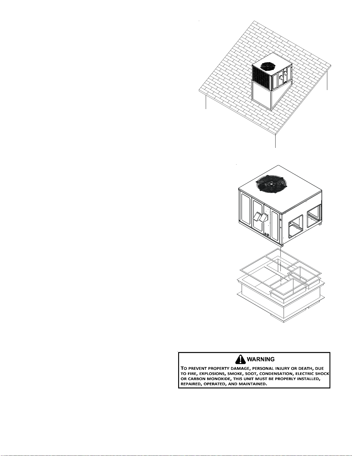
ROOFTOP INSTALLATIONS ONLY:
NOTE: To ensure proper condensate drainage, unit must be installed in
a level position.
• To avoid possible property damage or personal injury, the roof must
have sufficient structural strength to carry the weight of the unit(s)
and snow or water loads as required by local codes. Consult a
structural engineer to determine the weight capabilities of the
roof.
• The unit may be installed directly on wood floors or on Class A,
Class B, or Class C roof covering material.
• To avoid possible personal injury, a safe, flat surface for service
personnel should be provided.
ROOF CURB INSTALLATIONS ONLY:
• Sufficient structural support must be determined prior to locating
and mounting the curb and package unit.
• Ductwork must be constructed using industry guidelines. The duct work must be
placed into the roof curb before mounting the package unit.
• Curb insulation, cant strips, flashing and general roofing material are furnished by
the contractor.
GENERAL INFORMATION
This unit is approved for outdoor installation ONLY. To assure that your unit operates
safely and efficiently, it must be installed, operated, and maintained in accordance with
these installation and operating instructions, all local building codes and ordinances, or
in their absence, with the latest edition of the National Fuel
Gas Code NFPA 54/ANSI Z223.1 and National Standard of Canada
CAN/CSA B149 Installation Codes.
The heating and cooling capacities of the unit should be greater
than or equal to the design heating and cooling loads of the
area to be conditioned. The loads should be calculated by an
approved method or in accordance with A.S.H.R.A.E. Guide or
Manual J - Load Calculations published by the Air Conditioning
Contractors of America. Obtain from:
American National Standards Institute
25 West 43rd street, 4th Floor
New York, NY 10036
Rooftop Installation
Roof Curb Installation

8
RIGGING DETAILS
Refer to the Unit Installation Instructions for proper unit
installation. Curbing must be installed in compliance with the
National Roofing Contractors Association Manual.
Lower unit carefully onto roof mounting curb. While rigging unit,
center of gravity will cause condenser end to be lower than
supply air end.
GAS PIPING
IMPORTANT NOTE: This unit is factory set to operate on natural gas at
the altitudes shown on the rating plate.
The rating plate is stamped with the model number, type of gas and gas
input rating. Make sure the unit is equipped to operate on the type of
gas available. Conversion to LP gas is permitted with the use of the fac-
tory authorized conversion kit LPM-08.
Natural Min. 5.0" W.C., Max. 10.0" W.C.
Propane Min. 11.0" W.C., Max. 13.0" W.C.
INLET GAS PRESSURE
Inlet Gas Pressure Must Not Exceed the Maximum Value Shown in Table Above.
The minimum supply pressure should not vary from that shown in the table above because this could prevent the unit from having
dependable ignition. In addition, gas input to the burners must not exceed the rated input shown on the rating plate. Over firing
of the unit could result in premature heat exchanger failure.
HIGH ALTITUDE DERATE (U.S. INSTALLATIONS ONLY)
IMPORTANT NOTE: Installation of this gas/electric package unit at altitudes above 2000 ft (610 m) shall be made in accordance with
the Listed High Altitude Conversion Kit.
L’installation de ce générateur de chaleur à des altitudes supérieures à 2000 pi (610 m) doit être effectuée conformément aux
instructions accompagnant la trousse de conversion pour haute altitude fournie avec cet appareil.
The gas/electric units naturally derate with altitude. Do not attempt to increase the firing rate by changing orifices or increasing
the manifold pressure. This can cause poor combustion and equipment failure. At all altitudes, the manifold pressure must be
within 0.3 inches W.C. of that listed on the nameplate for the fuel used. At all altitudes and with either fuel, the air temperature rise
must be within the range listed on the unit nameplate.
Refer to the Installation Manual provided with the LP kit for conversion from natural gas to propane gas and for altitude adjustments.
Use HA02 for installations above 2000’.
NOTE: Up to 2,000 feet, no changes are required; above 2,000 feet, refer to the gas/electric package unit specification sheets for
required kit(s).
PIPING
IMPORTANT NOTE: To avoid possible unsatisfactory operation or equipment damage due to under firing of equipment, do not
undersize the natural/propane gas piping from the meter/tank to the unit. When sizing a trunk line, include all appliances on that
line that could be operated simultaneously.
The rating plate is stamped with the model number, type of gas and gas input rating. Make sure the unit is equipped to operate on
the type of gas available. The gas line installation must comply with local codes, or in the absence of local codes, with the latest
edition of the National Fuel Gas Code NFPA 54/ANSI Z223.1.
Rigging

9
Natural Gas Connection
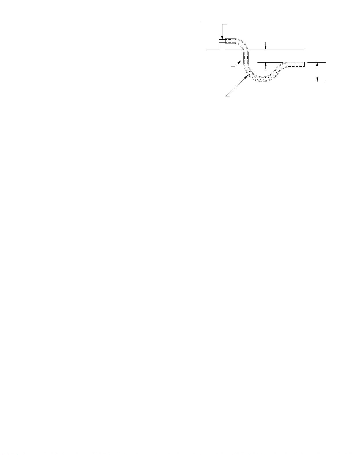
Refer to the Proper Piping Practice drawing for the general layout at
the unit. The following rules apply:
1. Use black iron pipe and fittings for the supply piping. The use
of a flex connector and/or copper piping is permitted as long
as it is in agreement with local codes.
2. Use pipe joint compound on male threads only. Pipe joint
compound must be resistant to the action of the fuel used.
3. Use ground joint unions.
4. Install a drip leg to trap dirt and moisture before it can enter
the gas valve. The drip leg must be a minimum of three inches
long.
5. Use two pipe wrenches when making connection to the gas
valve to keep it from turning.
6. Install a manual shut-off valve in a convenient location (within
six feet of unit) between the meter and the unit.
7. Tighten all joints securely.
8. The unit must be connected to the building piping by one of
the following methods:
• Rigid metallic pipe and fittings
• Semirigid metallic tubing and metallic fittings (Aluminum alloy tubing must not be used in exterior locations)
• Listed gas appliance connectors used in accordance with the terms of their listing that are completely in the same room
as the equipment
• In the preceding two methods the connector or tubing must be protected from physical and thermal damage. Aluminum
alloy tubing and connectors must be coated to protect against external corrosion when in contact with masonry,
plaster or insulation or are subject to repeated wettings by liquids (water - not rain water, detergents or sewage).
Proper Piping Practice
NOTE: The unit gas supply entrance is factory sealed with plugs.
Keep plugs in place until gas supply is ready to be installed.
Once ready, replace the plugs with the supplied grommets and
install gas supply line.
There will be air in the gas supply line after testing for leaks on
a new installation. Therefore, the air must be bled from the line
by loosening the ground joint union until pure gas is expelled.
Tighten union and wait for five minutes until all gas has been
dissipated in the air. Be certain there is no open flame in the
vicinity during air bleeding procedure. The unit is placed in op-
eration by closing the main electrical disconnect switch for the
unit.
Len
g
th of
Pipe in Feet 1/2 3/4 11 1/4 1 1/2
10 132 278 520 1050 1600
20 92 190 350 730 1100
30 73 152 285 590 980
40 63 130 245 500 760
50 56 115 215 440 670
60 50 105 195 400 610
70 46 96 180 370 560
80 43 90 170 350 530
90 40 84 160 320 490
100 38 79 150 305 460
Pressure = .50 PSIG or less and Pressure Drop of 0.3" W.C. (Based
on 0.60 Specific Gravity Gas)
Natural Gas Capacity of Pipe
in Cubic Feet of Gas Per Hour (CFH)
Nominal Black Pipe Size (inches)
BTUH Furnace Input
Heating Value of Gas (BTU/Cubic Foot)
CFH =
Piping
DRIP LEG
MANUAL
SHUT-OFF
VALVE
GROUND JOINT UNION
(INSTALLED AHEAD OF GAS VALVE)
GROMMET
10
Propane Gas Installations
IMPORTANT NOTE: Propane gas conversion kits must be installed
to convert units to propane gas. Refer to the gas piping section
for the correct LP kit for conversion.
All propane gas equipment must conform to the safety stan-
dards of the National Board of Fire Underwriters (See NBFU
Manual 58).
For satisfactory operation, propane gas supply pressure must be within 9.7 - 10.3 inches W.C. at the manifold with all gas appliances
in operation. Maintaining proper gas pressure depends on three main factors:
1. Vaporization rate, which depends on (a) temperature of the liquid, and (b) wetted surface area of the container or containers.
2. Proper pressure regulation.
3. Pressure drop in lines between regulators, and between second
stage regulator and the appliance. Pipe size required will depend
on length of pipe run and total load of all appliances.
Tanks and Piping
Complete information regarding tank sizing for vaporization, recom-
mended regulator settings and pipe sizing is available from most regu-
lator manufacturers and propane gas suppliers.
Since propane gas will quickly dissolve white lead or most standard
commercial compounds, special pipe dope must be used. Shellac base
compounds resistant to the actions of liquefied petroleum gases such
as Gasolac®, Stalactic®, Clyde’s®or John Crane®are satisfactory.
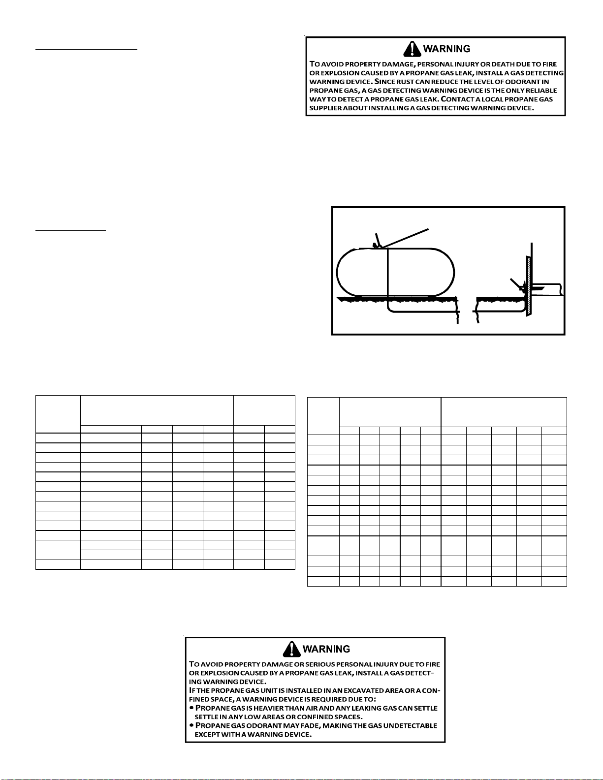
See following graphic for typical propane gas piping.
200 PSIG
Maximum
5 to 15 PSIG
(20 PSIG Max.) Continuous
11" W.C.
Second Stage
Regulator
First Stage
Regulator
Typical Propane Gas Piping
Sizing Between First and Second Stage Regulator
Maximum Propane Capacities listed are based on 1 PSIG Pressure Drop at 10
PSIG Setting. Capacities in 1,000 BTU/HR
3/8" 1/2" 5/8" 3/4" 7/8" 1/2" 3/4"
30 309 700 1,303 2,205 3,394 1,843 3,854
40 265 599 1,115 1,887 2,904 1,577 3,298
50 235 531 988 1,672 2,574 1,398 2,923
60 213 481 896 1,515 2,332 1,267 2,649
70 196 446 824 1,394 2,146 1,165 2,437
80 182 412 767 1,297 1,996 1,084 2,267
90 171 386 719 1,217 1,873 1,017 2,127
100 161 365 679 1,149 1,769 961 2,009
150 130 293 546 923 1,421 772 1,613
200 111 251 467 790 1,216 660 1,381
250 90 222 414 700 1,078 585 1,224
300 89 201 378 634 976 530 1,109
350 82 185 345 584 898 488 1,020
400 76 172 321 543 836 454 949
To convert to Capacities at 15 PSIG Settings -- Multiply by 1.130
To convert to Capacities at 5 PSIG Settings -- Multiply by 0.879
PIPE OR
TUBING
LENGTH,
FEET
NOMINAL PIPE SIZE,
SCHEDULE 40
TUBING SIZE, O.D., TYPE L
Sizing Between Single or Second Stage Regulator and Appliance*
Maximum Propane Capacities Listed are Based on 1/2" W.C. Pressure Drop at
11" W.C. Setting. Capacities in 1,000 BTU/HR
3/8" 1/2" 5/8" 3/4" 7/8" 1/2" 3/4" 1" 1-1/4" 1-1/2"
10 49 110 206 348 539 291 608 1,146 2,353 3,525
20 34 76 141 239 368 200 418 788 1,617 2,423
30 27 61 114 192 296 161 336 632 1,299 1,946
40 23 52 97 164 253 137 284 541 1,111 1,665
50 20 46 86 146 224 122 255 480 985 1,476
60 19 42 78 132 203 110 231 436 892 1,337
80 16 36 67 113 174 94 198 372 764 1,144
100 14 32 59 100 154 84 175 330 677 1,014
125 12 28 52 89 137 74 155 292 600 899
150 11 26 48 80 124 67 141 265 544 815
200 10 22 41 69 106 58 120 227 465 697
250 9 19 36 61 94 51 107 201 412 618
300 8 18 33 55 85 46 97 182 374 560
350 7 16 30 51 78 43 89 167 344 515
400 7 15 28 47 73 40 83 156 320 479
*DATA IN ACCORDANCE WITH NFPA PAMPHLET NO. 54
NOMINAL PIPE SIZE,
SCHEDULE 40
TUBING SIZE, O.D., TYPE L
PIPE OR
TUBING
LENGTH,
FEET
Propane Gas Pipe Sizing

11
WIRING
NOTE: All wiring should be made in accordance with the National Electrical Code.
Consult your local Power Company to determine the availability of sufficient power to operate the unit. Check the voltage,
frequency, and phase at the power supply to ensure it corresponds to the unit’s RATED VOLTAGE REQUIREMENT.
In accordance with the N.E.C. or local codes, install a branch circuit fused disconnect near the unit. Determine wire sizes and
overcurrent protection from the unit nameplate ampacity and in accordance with the Minimum Filter Size or the N.E.C. The wiring
should never be sized smaller than is recommended by either of these two sources.
Fuses smaller than that recommended on the rating plate could result in unnecessary fuse failure or service calls. The use of
protective devices of larger size than indicated could result in extensive damage to the equipment. The manufacturer bears no
responsibility for damage caused to equipment as result of the use of larger than is recommended size protective devices.
All units have undergone a run test prior to packaging for shipment. This equipment has been started at minimum rated voltage and
checked for satisfactory operation. Do not attempt to operate this unit if the voltage is not within the minimum and maximum
voltages shown on nameplate.
All exterior wiring must be within approved weatherproof conduit. The unit must be permanently grounded in accordance with
local codes, or in absence of local codes, with N.E.C. ANSI/
NFPA NO. 70-1984 or latest edition by using ground lug in the
control box.
Fuses or HACR type circuit breakers may be used where codes
permit.
IMPORTANT NOTE: Some single phase units are equipped with a
single-pole contactor. Exercise caution when servicing as only
one leg of the power supply is broken with the contractor.
HIGH VOLTAGE WIRING
The unit transformer is factory connected for 230V operation. If
the unit is to operate on 208V, reconnect the transformer primary
lead as shown on the unit wiring diagram. The induced draft blower
on some models is equipped with a low speed 230V lead (blue) and
a low speed 208V lead (black). If equipped, connect the induced
draft blower low speed 208V lead (black) in place of the low speed
230V lead (blue). Place the unused 230V lead on the “PARK” termi-
nal located on ignition control.
•Single Phase. Connect two leads to terminals L1 & L2 in
the electrical control section, using wire sizes specified in
wiring table.
THERMOSTAT CONTROLS
RECOMMENDED: TSTATGTS3275 (Emerson Dual Fuel thermostat) with TSTATTSORS outdoor
temperature sensor.
ALTERNATE: A 1-stage cool/2-stage heat pump thermostat with OTDFPKG-01 outdoor tem-
perature sensor kit.
IMPORTANT NOTE: For optimal performance, an outdoor temperature sensor should be used
with the control thermostat to determine when the unit switches from heat pump mode to
gas mode. The unit is compatible with a standard heat pump thermostat with a minimum of 1
cool - 2 heat. If an outdoor sensor is not installed, the gas will not ignite until the control
thermostat calls for a 2nd stage of heat.
LOW VOLTAGE WIRING
•Heat Pumps. Connect 24V wires from the thermostat to the corresponding wires in
the control box using No. 18 AWG as shown in the table at right:
INTERNAL WIRING
A diagram detailing the internal wiring of this unit is located on the Goodman labeled access panel. If any of the original wire
supplied with the appliance must be replaced, the wire gauge and insulation must be the same as the original wiring.
1. For branch circuit wiring (main power supply to unit disconnect), the minimum wire size for the length of run can be
determined using the circuit ampacity found on the unit rating plate and the table below. From the unit disconnect to the
unit, the smallest wire size allowable may be used for the ampacity, as the disconnect must be in sight of the unit.
2. Wire size based on 60°C rated wire insulation and 30°C Ambient Temperature (86°F).
3. For more than three conductors in a raceway or cable, see the N.E.C. for derating the ampacity of each conductor.
Wiring Table
BRANCH CIRCUIT AMPACITY 15 20 25 30 35 40 45 50
SUPPLY WIRE LENGTH - FEET
200 64443322
150 86644433
100 108866644
50 141210108866
Red R (24V)
Green G (fan)
Orange O (rev. valve)
White W1 (heat,2nd)
Brown W2 (heat,3rd)
Yellow Y(cool)
Blue C (24VCommon)
[A/G]PD14
Terminal
Wire
24 - 48
Thermostat
12
For unit protection, use a fuse or HACR circuit breaker that is in
excess of the circuit ampacity, but less than or equal to the
maximum overcurrent protection device. DO NOT EXCEED THE
MAXIMUM OVERCURRENT DEVICE SIZE SHOWN ON UNITDATAPLATE.
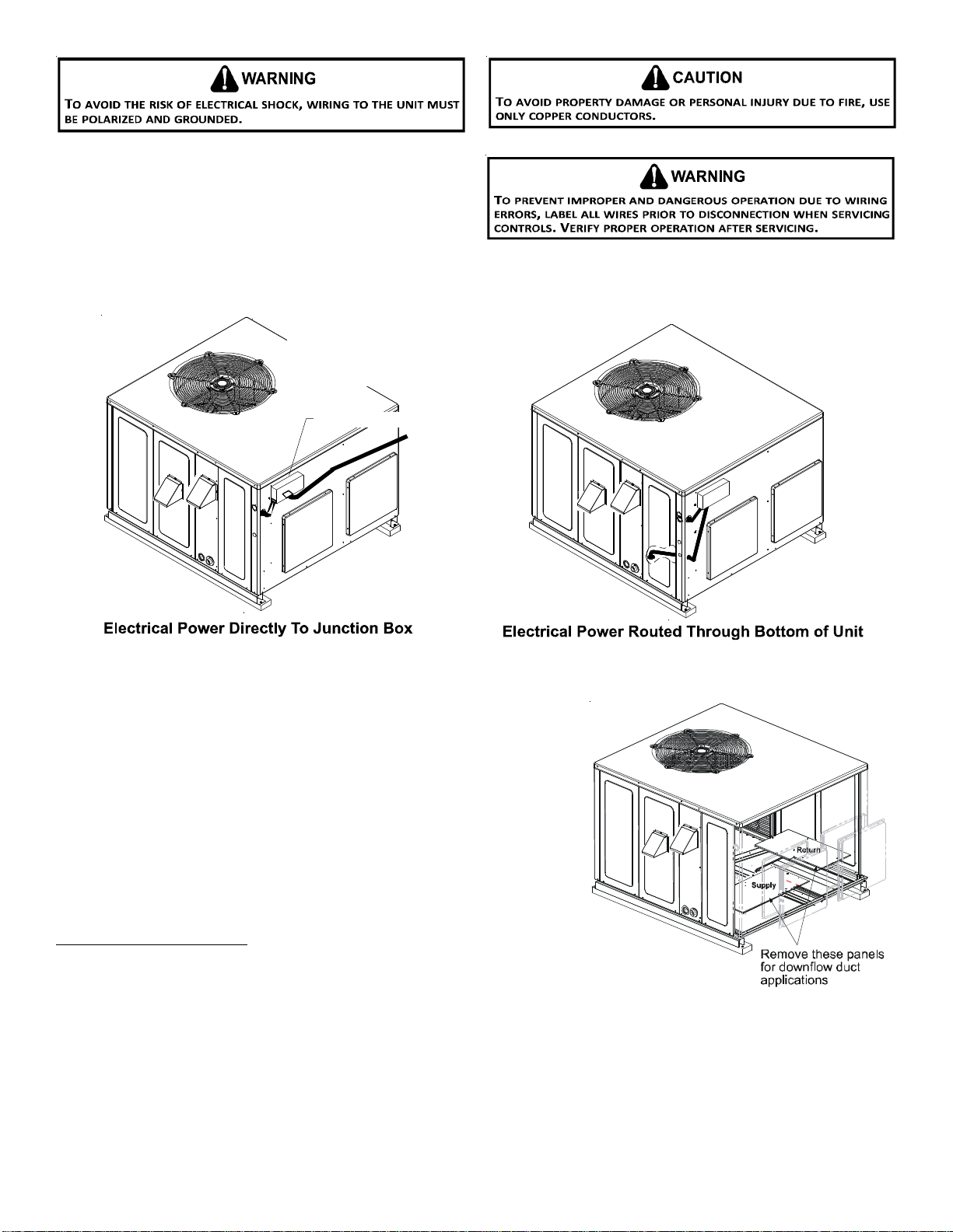
All line voltage connections must be made through weather-
proof fittings. All exterior power supply and ground wiring must
be in approved weatherproof conduit. Low voltage wiring from
the unit control panel to the thermostat requires coded cable. See below for ground level and rooftop wiring.
CIRCULATING AIR AND FILTERS
AIRFLOW CONVERSION
Units can easily be converted from horizontal to down-discharge airflow delivery.
In down-discharge or high static installations, the installer should measure the
total external static and review the blower performance charts before perform-
ing the installation. In some installations it will be necessary to change the blower
speed to provide proper air flow.
HORIZONTAL AIR FLOW
Single phase models are shipped without horizontal duct covers. If needed, these
kits may be ordered through Goodman’s Service Parts department.
Down Discharge Applications
Cut insulation around bottom openings and remove panels from the bottom of
the unit, saving the screws holding the panels in place.
NOTE: Single phase models require installation of horizontal duct kit
#20464501PDGK (medium chassis) and #20464502PDGK (large chassis).
DUCTWORK
Duct systems and register sizes must be properly designed for the C.F.M. and external static pressure rating of the unit. Ductwork
should be designed in accordance with the recommended methods of Air Conditioning Contractors of America Manual D (Residen-
tial) or Manual Q (Commercial). All ductwork exposed to the outdoors must include a weatherproof barrier and adequate insulation.
A duct system should be installed in accordance with Standards of the National Board of Fire Underwriters for the Installation of Air
Conditioning, Warm Air Heating and Ventilating Systems. Pamphlets No. 90A and 90B.
Duct Cover Installation
Typical Electrical Wiring Unit Voltage
Note:Junction box location
shown is optional and is
for illustration purposes only.
JUNCTION BOX

13
The supply duct from the unit through a wall may be installed without clearance. However, minimum unit clearances as shown in the
appendix must be maintained. The supply duct should be provided with an access panel large enough to inspect the air chamber
downstream of the heat exchanger. A cover should be tightly attached to prevent air leaks.
For duct flange dimensions on the unit refer to the Unit Dimension illustration in the appendix.
For down-discharge applications, the ductwork should be attached to the roof curb prior to installing the unit. Ductwork dimen-
sions are shown in the roof curb installation manual.
If desired, supply and return duct connections to the unit may be made with flexible connections to reduce possible unit operating
sound transmission.
FILTERS
Even though a return air filter is not supplied with this unit,
there must be a means of filtering all return air. All units may be
externally filtered.
Refer to the unit filter size chart in the appendix for filter size
information.
Filters installed external to the unit should be sized in accordance with their manufacturer recommendations. A throwaway filter
must be sized for a maximum face velocity of 300 feet per minute.
Filter Installation
IMPORTANT NOTE: When installing a filter, the air flow arrows on the filter must point toward the circulator blower.
VENTING
NOTE: Venting is self-contained. Do not modify or block.
INSTALLATION - FLUE HOOD EXHAUST
1. Locate the flue hood assembly box from the blower compartment.
2. Slide screen over flanges on the lower flue hood.
3. Slide screen into hood.
4. Using the three screws provided, attach the hood (with the opening
facing down) over the flue exhaust opening in the utility panel.
INSTALLATION - COMBUSTION AIR INTAKE HOOD
1. Locate the second hood.
2. Using the three screws provided, attach the hood (with
the opening facing down) to the heat exchanger access
door.
SCREEN
HOOD
LOWER
FLUE
HOOD
LIP
14
CONDENSATE DRAIN
CONDENSATE DRAIN CONNECTION
A 3/4” NPT drain connection is supplied for condensate piping. An
external trap must be installed for proper condensate drainage.
NORMAL SEQUENCES OF OPERATION
HEAT PUMP OPERATION
OUTDOOR THERMOSTAT
For optimal performance, a dual fuel thermostat with an outdoor tem-
perature sensor should be used. TSTATGTS3275 (Emerson Dual Fuel thermostat) with TSTATTSORS (outdoor temperature sensor) is
recommended.
This will allow the installer to control when the unit switches from heat pump to gas heat based on a set point entered into the
thermostat. It is recommended to set the thermostat between 35° - 45°F, depending on regional climate and energy rates.
OPTIONAL OUTDOOR THERMOSTAT (OTDFPKG-01)
The outdoor thermostat is an optional accessory that can be set from 0 - 45°F and is set inside a “birdhouse” enclosure. This
enclosure will be mounted near the blower access panel. The dimples and knock-out are located on the corner posts, providing
ease of installation. Once the thermostat closes, a 24 volt signal is sent to the W1 terminal instead of the Y terminal and the heating
cycle will change from Heat Pump to Gas heating. It is recommended to set the thermostat between 35-45°F depending on regional
climate and energy rates.
HEATING CYCLE (HEAT PUMP)
The heat pump operates in the heating cycle by redirecting refrigerant flow through the refrigerant circuit external to the
compressor. This is accomplished through the reversing valve. Hot discharge vapor from the compressor is directed to the indoor
coil (evaporator on the cooling cycle) where the heat is removed, and the vapor condenses to liquid. It then goes through the
expansion device to the outdoor coil (condenser on the cooling cycle) where the liquid is evaporated, and the vapor goes to the
compressor.
When the solenoid valve coil is energizing for cooling, the piston in the reversing valve to the low pressure (high pressure) reverse
positions in the reversing valve. In addition to a reversing valve, a heat pump is equipped with an expansion device for the indoor
coil, and similar equipment for the outdoor coil is provided with a defrost control system.
HEATING CYCLE (NATURAL GAS/ LP)
1. The Dual Fuel unit will operate in gas heat mode when the thermostat calls for a W-1 or W-2 signal. If outdoor thermostat is
installed, the unit will operate in gas heat when ambient is below set point or the unit receives call for low or high stage gas
heat.
2. Induced draft blower energizes for 15-second pre-purge.
3. A 7-second trial for ignition begins by energizing the low and high stages of the gas valve along with this spark ignition.
NOTE: The igniter produces a very intense electrical spark that ignites the gas.
4. Main burners light and control detects presence of flame.
5. If the call is for low stage heat, the induced draft blower switches from high to low speed and the gas valve from high to low
stage within 5 seconds after the main burners light. If call is for high stage heat, induced draft blower remains at high speed
and high stage gas valve remains open.
NOTE: If a W2 is not used, the control will step to low stage after the main burners light and remain at low stage for 5 or
10 minutes, depending on jumper position. If the jumper is set to none, you will never get a call for high stage heat. If the
call for HEAT remains after the transition delay time expires, the control will transition from low stage to high stage.
6. The 30-second HEAT FAN ON delay time begins after the main burners light.
7. The unit delivers heat to the conditioned space until the thermostat is satisfied.
8. Gas valve(s) de-energizes. The induced draft blower continues operation for a 30-second post-purge.
NOTE: Induced draft blower remains at low speed (or switches from high to low if operating at high stage heat) for the 30-
second post purge.
9. Ignition control begins timing the HEAT FAN OFF delay. There is an adjustable HEAT FAN OFF delay of approximately 90/120/
150/180 seconds (factory set at 150). If the unit is operating at high stage when the call for heat is removed, the blower will
operate for 30 seconds at high heat speed then switch to low heat speed for the remainder of the selected HEAT FAN OFF
delay.
NOTE: After the HEAT FAN OFF delay time has elapsed, the blower will de-energize. This allows any additional heat in the heat
exchanger to be transferred to the conditioned space.
DRAIN
CONNECTION
UNIT 2" MINIMUM
FLEXIBLE
TUBING-HOSE
OR PIPE 3" MINIMUM
A POSITIVE LIQUID
SEAL IS REQUIRED
Drain Connection

15
DEFROST CYCLE
NOTE: The defrost board is equipped with a jumper for SmartShift™ defrost technology operation. This operation turns the
compressor off for 30 seconds at defrost initiation and termination. The unit is factory shipped for SmartShift™ defrost technology
operation. To operate unit at rated efficiencies, move the jumper on the defrost board from “DLY” to “NORM”.
During operation the power to the circuit board is controlled by a temperature sensor, which is clamped to a feeder tube entering
the outdoor coil. Defrost timing periods of 30, 60 and 90 minutes may be selected by setting the circuit board jumper to 30, 60 and
90 respectively.
Accumulation of time for the timing period selected starts when the sensor closes (approximately 34°F), and when the wall
thermostat calls for heat. At the end of the timing period, the unit’s defrost cycle will be initiated provided the sensor remains
closed.
Upon a call for defrost, the blower will continue to run and the defrost board will send a W1 signal to the ignition control. At the
same time the compressor will stop for 30 seconds, if the SmartShift™ defrost technology delay feature is selected on the defrost
board. At this time, the reversing valve shifts from heat to cool position and condenser fans shut off. The inducer motor will
immediately energize for a 15 second prepurge.
A 7-second trial for ignition begins by energizing the low and high stages of the gas valve along with this spark ignition. Main burners
light and control detects presence of flame. The compressor (after its 30/OFF second delay) restarts in cooling mode to defrost the
condensor coil.
When the sensor opens (approximately 60°F), the defrost cycle is terminated and the timing period is reset. If the defrost cycle is
not terminated due to the sensor temperature, a twelve minute override interrupts the unit’s defrost period. At this time the W1
signal is removed from the ignition control board, the compressor will stop for a 30 second SmartShift™ defrost technology delay (if
selected) and the reversing valve slides back to its normal heat position.
COOLING
1. Thermostat calls for cooling.
2. When the thermostat call is for cooling, the compressor and outdoor fan are energized .
3. The indoor blower will energize approximately 6 seconds later.
4. The unit delivers cooling to the conditioned space until the thermostat is satisfied.
5. The compressor and outdoor fan will be de-energized when the thermostat opens.
6. The indoor blower continues to run at low cool speed for approximately 60 seconds after the thermostat is satisfied. This
allows additional cooling from the indoor coil to be transferred to the conditioned space. Then, the indoor blower is de-
energized.
NOTE: A 180-second anti-short cycle is integral to the control and prevents recycling of the compressor.
Cooling Operation
NOTE: Mechanical cooling cannot be reliably provided at ambient temperatures below 50° F.
1. Turn on the electrical power supply to the unit.
2. Place the room thermostat selector switch in the COOL position (or AUTO if available, and if automatic changeover from
cooling to heating is desired).
3. Set the room thermostat to the desired temperature.
FAN ONLY
1. Thermostat calls for FAN ONLY by energizing “G”.
2. The indoor blower is immediately energized at the low heat speed.
3. The indoor blower is immediately de-energized once thermostat call for FAN is removed.
AIR FLOW MEASUREMENT AND ADJUSTMENT
Please review the Duct Work section before proceeding with the airflow measurements and adjustments in this section.
Unit blower curves (see Specification Sheets) are based on external static pressure (ESP per in/W.C.). The duct openings on the
unit are considered internal static pressure. As long as ESP is maintained, the unit will deliver the proper air up to the maximum
static pressure listed for the CFM required by the application (i.e. home, building, etc.)
In general, 400 CFM per ton of cooling capacity is a rule of thumb. Some applications depending on the sensible and latent capacity
requirements may need only 350 CFM or up to 425 CFM per ton. Check condition space load requirements (from load calculations)
and equipment expanded ratings data to match CFM and capacity.
After unit is set and duct work completed, verify the ESP with a 1-inch inclined manometer with pilot tubes or a Magnahelic gauge
and confirm CFM to blower curves in the Specification Sheets.
NOTE: Never run CFM below 350 CFM per ton, evaporator freezing or poor unit performance is possible.
AIR FLOW ADJUSTMENTS FOR INDOOR BLOWER MOTOR
EEM Motor
Adjust the CFM by changing the 24V low voltage lead at the speed terminal block on the motor. (T1, T2, T3, T4, T5). See Blower
Performance Data in the appendix for airflow delivered at each speed tap.
NOTE: Factory set T1 (G, fan and low stage gas heat), T2 (high stage gas heat, T4 (nominal heat pump / cooling).
T3 is for optional low speed cooling and heat pump. T5 is for optional high speed cooling and heat pump.

16
START-UP, ADJUSTMENTS, AND CHECKS
HEATING START-UP ( NATURAL GAS / LP)
This unit is equipped with an electronic ignition device to automatically light the main burners. It also has a power vent blower to
exhaust combustion products.
On new installations, or if a major component has been replaced, the operation of the unit must be checked.
Check unit operation as outlined in the following instructions. If any sparking, odors, or unusual sounds are encountered, shut off
electrical power and check for wiring errors, or obstructions in or near the blower motors.
Heat Anticipator Setting
Set the heat anticipator on the room thermostat to 0.4 amps to obtain the proper
number of heating cycles per hour and to prevent the room temperature from
overshooting the room thermostat setting.
Rollout Protection Control
The rollout protection device opens, cutting power to the gas valve, if the flames
from the burners are not properly drawn into the heat exchanger. The rollout
protection device is located on the burner bracket. The reason for elevated tem-
peratures at the control must be determined and repaired prior to resetting this
manual reset control.
Secondary Limit Control
The secondary limit control is located on the top of the blower scroll assembly. This
control opens when elevated temperatures are sensed. Elevated temperatures at the
control are normally caused by blower failure.
If the power to the unit is interrupted during the heating cycle, it may cause the
secondary limit to trip. Once the blower compartment temperature drops below the
limit reset temperature, the limit will automatically reset.
Pre-Operation Checks
1. Close the manual gas valve external to the unit.
2. Turn off the electrical power supply to the unit.
3. Set the room thermostat to its lowest possible setting.
4. Remove the heat exchanger door on the side of the unit by
removing screws.
5. This unit is equipped with an ignition device which automatically
lights the main burner. DO NOT try to light burner by any other
method.
6. Move the gas control valve switch to the OFF position. Do not
force.
7. Wait five minutes to clear out any gas.
8. Smell for gas, including near the ground. This is important because
some types of gas are heavier than air. If you have waited five
minutes and you do smell gas, immediately follow the warnings
on page 4 of this manual. If having waited for five minutes and no
gas smell is noted, move the gas control valve switch to the ON
position.
9. Replace the heat exchanger door on the side of the unit.
10.Open the manual gas valve external to the unit.
11.Turn on the electrical power supply to the unit.
12.Set the thermostat to desired setting.
Rollout Protection
Rollout Protection on Burner Bracket
Secondary
Control Limit
Back of Unit
Secondary Limit Control
On/Off Switch
Inlet
Pressure Boss High Fire
Coil Terminal (HI)
Low Fire
Regulator Adjust
Manometer
Manometer
Hose
A
High Fire Regulator
Adjust Regulator
Vent
Common
Terminal (C)
Coaxial Coil
Terminal (M)
Outlet
Pressure Boss
Open to
Atmosphere
White-Rodgers Model 36G54 connected to Manometer

17
Gas Supply And Manifold Check
Gas supply pressure and manifold pressure with the burners operating must be as specified on the rating plate.
Gas Inlet Pressure Check
Gas inlet pressure must be checked and adjusted in accordance to the type of fuel being consumed.
With Power And Gas Off:
1. Connect a water manometer or adequate gauge to the inlet pressure tap of the gas valve.
Inlet gas pressure can also be measured by removing the cap from the drip leg and installing a predrilled cap with a hose
fitting.
With Power And Gas On:
2. Put unit into heating cycle and turn on all other gas consuming
appliances.
NOTE: Inlet Gas Pressure Must Not Exceed the Maximum Value Shown
in the Inlet Gas Pressure chart.
If operating pressures differ from above, make necessary pressure regulator adjustments, check
piping size, etc., and/or consult with local utility.
Manifold Pressure Check
1 Turn OFF gas to furnace at the manual gas shutoff valve external to the furnace.
2. Turn off all electrical power to the system.
3. Back outlet pressure test screw (inlet/outlet pressure boss) out one turn (counterclockwise,
not more than one turn).
4. Attach a hose and manometer to the outlet pressure boss of the valve.
5. Turn ON the gas supply.
6. Turn on power and energize main (M) solenoid. Do not energize the HI solenoid.
7. Measure gas manifold pressure with burners firing. Adjust manifold pressure using the Manifold
Gas Pressure table.
8. Remove regulator cover screw from the low (LO) outlet pressure regulator adjust tower and
turn screw clockwise to increase pressure, or counterclockwise to decrease pressure.
9. Energize main (M) solenoid as well as the HI terminal.
10.Remove regulator cover screw from the HI outlet pressure regulator adjust tower and turn
screw clockwise to increase pressure, or counterclockwise to decrease pressure.
11.Turn off all electrical power and gas supply to the system.
12.Remove manometer hose from outlet pressure boss.
13.Turn outlet pressure test screw in to seal pressure port (clockwise,
7 in-lb minimum).
14.Turn on electrical power and gas supply to the system.
15.Turn on system power and energize valve.
16.Using a leak detection solution or soap suds, check for leaks at
pressure boss screw. Bubbles forming indicate a leak. SHUT OFF
GAS AND FIX ALL LEAKS IMMEDIATELY.
NOTE: For gas to gas conversion, consult your dealer for appropriate
conversion.
Gas Input (Natural Gas Only) Check
To measure the gas input use a gas meter and proceed as follows:
1. Turn off gas supply to all other appliances except the unit.
2. With the unit operating, time the smallest dial on the meter for one complete revolution. If this is a 2 cubic foot dial, divide
the seconds by 2; if it is a 1 cubic foot dial, use the seconds as is. This gives the seconds per cubic foot of gas being delivered
to the unit.
3. INPUT=GAS HTG VALUE x 3600 / SEC. PER CUBIC FOOT
Example: Natural gas with a heating value of 1000 BTU per cubic foot and 34 seconds per cubic foot as determined by Step 2, then:
Input = 1000 x 3600 / 34 = 106,000 BTU per Hour. NOTE: BTU content of the gas should be obtained from the gas supplier. This
measured input must not be greater than shown on the unit rating plate.
4. Relight all other appliances turned off in step 1. Be sure all pilot burners are operating.
Main Burner Flame Check
Flames should be stable, soft and blue (dust may cause orange tips but they must not be yellow) and extending directly
outward from the burner without curling, floating or lifting off.
Gas Line
Gas
Shutoff
Valve
Gas Line
To Furnace
Drip Leg Cap
With Fitting
Manometer Hose
Manometer
Open To
Atmosphere
Measuring Inlet Gas Pressure
Alternate Method
Range Nominal
Natural Low Stage 1.6 - 2.2" w.c. 2.0" w.c.
High Stage 3.2 - 3.8" w.c. 3.5" w.c.
Propane Low Stage 5.7 - 6.3" w.c. 6.0" w.c.
High Stage 9.7 -10.3" w.c. 10.0" w.c.
Gas Manifold Gas Pressure
Manifold Gas Pressure
Inlet Gas Pressure
Natural Min. 5.0" W.C., Max. 10.0" W.C.
Propane Min. 11.0" W.C., Max. 13.0" W.C.
INLET GAS PRESSURE
18
Temperature Rise Check
Check the temperature rise through the unit by placing thermometers in supply and return air registers as close to the unit
as possible. Thermometers must not be able to sample temperature directly from the unit heat exchangers, or false readings
could be obtained.
1. All registers must be open; all duct dampers must be in their final (fully or partially open) position and the unit operated for
15 minutes before taking readings.
2. The temperature rise must be within the range specified on the rating plate.
NOTE: Air temperature rise is the temperature difference between supply and return air.
With a properly designed system, the proper amount of temperature rise will normally be obtained when the unit is operated at
rated input with the recommended blower speed.
If the correct amount of temperature rise is not obtained, it may be necessary to change the blower speed. A higher blower speed
will lower the temperature rise. A slower blower speed will increase the temperature rise.
NOTE: Blower speed MUST be set to give the correct air temperature rise through the unit as marked on the rating plate.
External Static Pressure Check
The total external static pressure must be checked on this unit to determine if the airflow is proper.
Blower Speed Adjustments
Refer to the wiring diagram and airflow data in the appendix to
verify speed tap settings.
Depending upon the model, blower speeds are changed at the
indoor blower. The ignition control board has four blower speeds:
LOW HEAT, HI HEAT, LOW COOL and HIGH COOL.
NOTE: FAN ONLY energizes at LOW HEAT speed.
The *PD14 models are equipped with EEM motors. EEM motors are
constant torque motors with very low power consumption. This
motor is energized by 24VAC. Adjust the CFM for the unit by
changing the 24VAC leads to the speed terminal block on the
motor.
NOTE: Heating airflow must be adjusted to provide the temperature
rise shown on rating plate. A higher speed tap may not provide
more airflow. Blower speeds are programmed to deliver adequate
airflow at rated external static pressure (ESP). Refer to airflow
table provided in the Appendix for details.
Limit Check
Check limit control operation after 15 minutes of operation by
blocking the return air grille(s).
1. After several minutes the main burners must go OFF. Blower will continue
to run.
2. Remove air restrictions and main burners will relight after a cool down
period of a few minutes.
Adjust the thermostat setting below room temperature.
1. Main burners must go OFF.
2. CirculatingAir Blower will continue to run for 90, 120, 150 or 180 seconds,
depending on the setting.
NOTE: If necessary, adjust fan OFF delay settings to obtain satisfactory com-
fort level.
Unit Shutdown
1. Set the thermostat to lowest setting.
2. Turn off the electrical power supply to the unit.
3. Remove the heat exchanger door on the side of the unit by removing
screws.
4. Move the gas control valve switch to the OFF position. Do
not force.
5. Close manual gas shutoff valve external to the unit.
6. Replace the heat exchanger door on the unit.
7. If cooling and/or air circulation will be desired, turn ON
the electrical power.
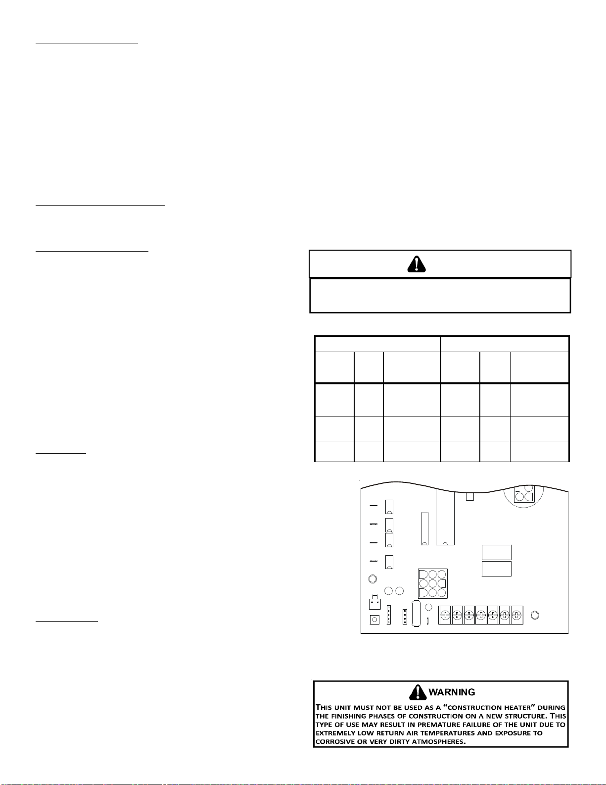
WARNING
TO AVOID PERSONAL INJURY OR DEATH DUE TO ELECTRIC SHOCK, REMOVE
ELECTRICAL POWER FROM THE UNIT BEFORE CHANGING SPEED TAPS ON THE
BLOWER MOTOR.
Lead
Color Speed
Tap Definition Lead
Color Speed
Tap Definition
White T1 Low
Speed Heat T3 Cool/HP
Optional Low
Speed
Brown T2 High
Speed Heat Yellow T4 Cool/HP
Speed
T5 High Static
GAS HEATING COOLING
LOCOOL
HICOOL
LOHEAT
HIHEAT
U6
U7
U4
U5
U3 K2
K1
P1
ECON
STAGE
DELAY
SPEEDUP
SW1
FAULT
RECALL BLOWER
OFFDELAY
F1
R C W1 W2 GY1Y2
Control Board (Top)

19
COOLING START-UP
NOTE: Check all manual reset limit controls in heating circuit if
cooling mode does not operate.
Compressor Protection Devices
The compressor includes components which are designed to
protect the compressor against abnormal operating conditions.
Refrigerant Charge Check (Units with Fixed Orifice Devices)
After completing airflow measurements and adjustments the unit’s re-
frigerant charge must be checked. The unit comes factory charged, but
this charge is based on 325 CFM per ton and minimum ESP per AHRI test
conditions (generally between .15 -.28 ESP). When air quantity or ESP is
different than above, the refrigerant charge must be adjusted to the
proper amount. All package units with fixed orifice devices are charged
using the super heat method at the compressor suction line.
After superheat is adjusted it is recommended to check unit sub-cooling
at the condenser coil liquid line out. For charge adjustments, see super-
heat and subcooling charts shown for each model.
MAINTENANCE
Have the gas heating section of the unit checked at least once a
year before the heating season begins, to be sure that the com-
bustion air inlet and flue outlet hoods are not blocked by debris,
which would prevent adequate combustion air and a properly
operating vent system.
FILTER REPLACEMENT OR CLEANING
A return air filter is not supplied with this unit; however, there
must be a means of filtering all of the return air. The filter(s) may
be located in the return air duct(s), or return air filter grille(s). Consult with your installing dealer for the actual location of the
return air filter(s) for your unit.
Dirty filters are the most common cause of inadequate heating or cooling performance. Filter inspection should be made at least
every two months; more often if necessary because of local conditions and usage.
Dirty throwaway filters should be discarded and replaced with a new, clean filter. Dirty permanent filters should be washed with
water, thoroughly dried and sprayed with a filter adhesive before being reinstalled. (Filter adhesives may be found at many hardware
stores.) Permanent filters should last several years. However, should one become torn or uncleanable, it should be replaced.
CABINET FINISH MAINTENANCE
Use a fine grade automotive wax on the cabinet finish to maintain the finish’s original high luster. This is especially important in
installations with extended periods of direct sunlight.
CLEAN OUTSIDE COIL (QUALIFIED SERVICER ONLY)
The coil with the outside air flowing over it should be inspected annually and cleaned as frequently as necessary to keep the finned
areas free of lint, hair and debris.
CONDENSER, EVAPORATOR, AND INDUCED DRAFT MOTORS
Bearings on the air circulating blower motor, condenser motor and the combustion fan
motor are permanently lubricated. No additional oiling is required.
FLAME SENSOR (QUALIFIED SERVICER ONLY)
A drop in the flame current can be caused by a nearly invisible coating on the flame sensor.
This coating, created by the fuel or combustion air supply, can be removed by carefully
cleaning the flame sensor with steel wool.
NOTE: After cleaning, the microamp signal should be stable and in the range of 4 - 6 microamps
DC.
FLUE PASSAGES (QUALIFIED SERVICER ONLY)
At the start of each heating season, inspect and, if necessary, clean the unit flue passage.
1. Shut off electric power and gas supply to the unit.
2. Remove burner assembly by disconnecting the gas line and removing the manifold bracket
from the partition panel.
Models # Superheat ± 3°F Subcooling± 3°F
A/GPD1424***M41 10 11
A/GPD1430***M41 610
A/GPD1436***M41 11 10
A/GPD1437***M41 11 10
A/GPD1442***M41 815
A/GPD1448***M41 13 10
Design superheat & subcooling
@ 95 °Foutdoor ambient temperature
Flame
Sensor
Flame Sensor
20
3. Remove the flue from the induced draft blower and the collector box cover from the partition panel.
4. The primary heat exchanger tubes can be cleaned using a round wire brush attached to a length of high grade stainless steel
cable, such as drain cleanout cable. Attach a variable speed reversible drill to the other end of the spring cable. Slowly rotate
the cable with the drill and insert it into one of the primary heat exchanger tubes. While reversing the drill, work the cable
in and out several times to obtain sufficient cleaning. Use a large cable for the large tube, and then repeat the operation with
a small cable for the smaller tube. Repeat for each tube.
5. When all heat exchanger tubes have been cleaned, replace the parts in the reverse order in which they were removed.
6. To reduce the chances of repeated fouling of the heat exchanger, perform the steps listed in “Start-up, Adjustments, and
Checks”.
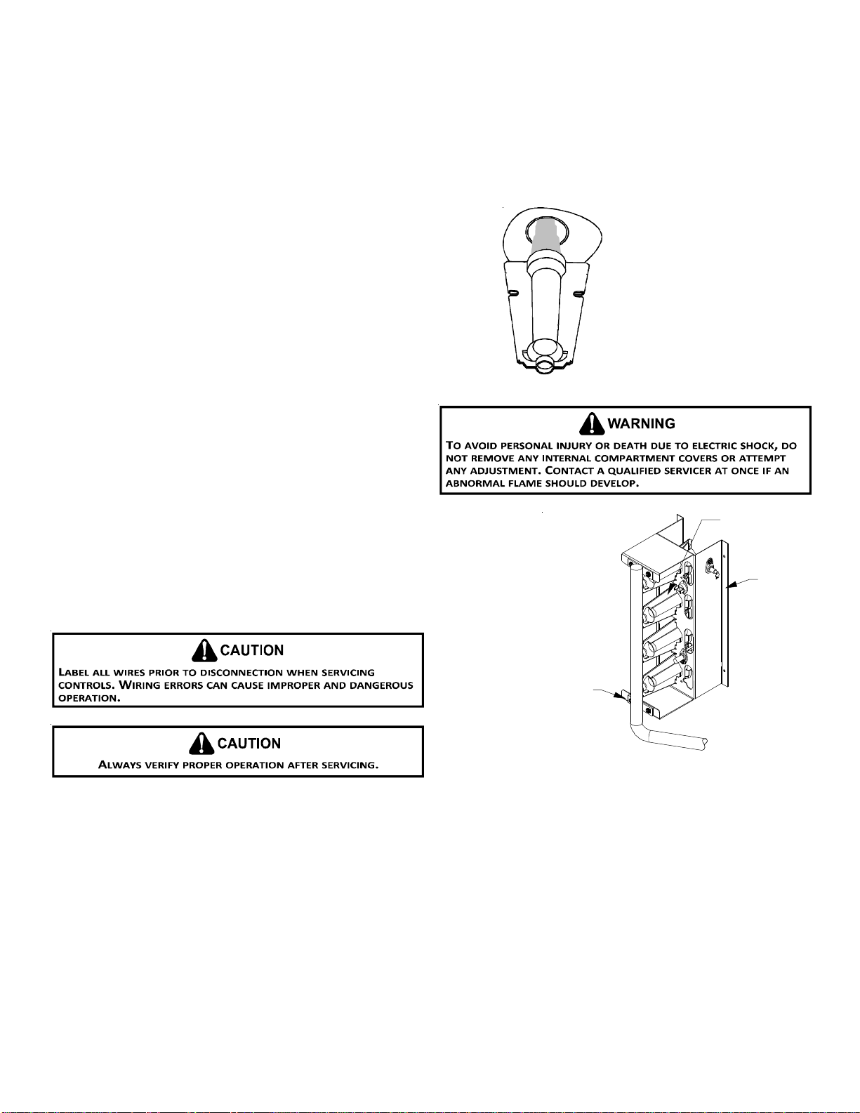
MAIN BURNER FLAME (QUALIFIED SERVICER ONLY)
Flames should be stable, soft and blue (dust may cause orange
tips but must not be yellow). The flames must extend directly
outward from the burner without curling, floating or lifting off.
At least once a year, prior to or during the heating season, make
a visual check of the burner flames.
NOTE: This will involve removing and reinstalling the heat ex-
changer door on the unit, which is held by two screws. If you
are uncertain about your ability to do this, contact a qualified
servicer.
If a strong wind is blowing, it may alter the airflow pattern within
the unit enough that an inspection of the burner flames is not
possible.
1. Shut off electric power and gas supply to the unit.
2. Remove the screws securing the manifold to the burner
retention bracket. Remove the manifold and rotate each
burner counterclockwise to remove.
3. Remove the burners.
4. Use a bottle brush to clean burner insert and inside of the burners.
5. Replace burners and manifold, inspect the burner assembly for proper seating
of burners in retention slots.
6. Reconnect electrical power and gas supply.
Check the burner flames for:
1. Good adjustment
2. Stable, soft and blue
3. Not curling, floating, or lifting off.
Burner Flame
Burner
Bracket
Burner
Manifold
Manifold Assembly
For further information on the yearly inspection, consult the User Manual. It is recommended that a qualified servicer inspect
and service the unit at least once each year.
Turn the unit on at the thermostat. Wait a few minutes, since any dislodged dust will alter the normal flame appearance. Flames
should be predominantly blue and directed into the tubes. They should not be yellow. They should extend directly outward from
the burner ports without curling downward, floating or lifting off the ports.
This manual suits for next models
5
Table of contents


